GeoVision GV-BX110D User Manual
Hide thumbs
Also See for GV-BX110D:
- User manual (484 pages) ,
- Quick start manual (130 pages) ,
- Quick start manual (96 pages)
Table of Contents
Advertisement
Quick Links
See also:
User Manual
Advertisement
Table of Contents

Related Manuals for GeoVision GV-BX110D


Summary of Contents for GeoVision GV-BX110D
- Page 1 GV-IPCam H.264 User's Manual Before attempting to connect or operate this product, please read these instructions carefully and save this manual for future use.
- Page 2 GeoVision. Every effort has been made to ensure that the information in this manual is accurate. GeoVision, Inc. makes no expressed or implied warranty of any kind and assumes no responsibility for errors or omissions. No liability is assumed for incidental or consequential damages arising from the use of the information or products contained herein.
- Page 3 The GV-IPCAM H.264 has a series of models designed to meet different needs. This Manual is designed for the following models and firmware versions: Model Model Number Firmware Version Fixed Lens V1.07 GV-BX110D Varifocal Lens GV-BX120D Varifocal Lens V1.0 Box Camera GV-BX220D Varifocal Lens V1.0...
-
Page 4: Table Of Contents
Chapter 2 Box Camera ............ 5 2.1 Packing List................6 2.2 Features..................6 2.3 Options..................7 2.4 Overview ..................8 2.4.1 GV-BX110D .................8 2.4.2 GV-BX120D / 220D / 320D ..........10 2.5 Focus Adjustment ..............11 2.6 Optional Installation ..............12 2.6.1 C-Mount Lenses..............12 2.6.2 Infrared Illuminators............13... - Page 5 Chapter 4 Bullet Camera ..........20 4.1 Packing List................20 4.2 Features................... 21 4.3 Options..................22 4.4 Installation................23 4.4.1 Connecting to the Data Cable........25 4.4.2 Adjusting Bullet Camera’s Angles ........28 4.4.3 Adjusting Lens and Inserting a Micro SD Card....31 4.4.4 Installing the Sun-Shield Cover ..........34 Chapter 5 PTZ Camera ..........
- Page 6 Chapter 6 PT Camera............. 65 6.1 Packing List................65 6.2 Features................... 66 6.3 Options..................67 6.4 Installation................67 6.5 Overview .................. 68 6.6 Focus Adjustment ..............70 6.7 I/O Terminal Block ..............71 6.7.1 Pin Assignment ..............71 6.8 PT Control................72 Chapter 7 Getting Started ..........
- Page 7 8.2.12 I/O Control................98 8.2.13 Visual Automation ............99 8.2.14 Network Status...............100 Chapter 9 Administrator Mode ........101 9.1 Video and Motion ..............103 9.1.1 Video Settings ..............104 9.1.2 Motion Detection ..............113 9.1.3 Privacy Mask..............114 9.1.4 Text Overlay..............115 9.1.5 Tampering Alarm..............116 9.1.6 Visual Automation ............118 9.2 I/O Settings ................
- Page 8 9.7.2 Advanced TCP/IP.............143 9.7.3 IP Filter Settings ...............145 9.8 Management ................146 9.8.1 Date & Time Settings ............146 9.8.2 GPS Maps Settings ............148 9.8.3 Storage Settings...............150 9.8.4 User Account..............152 9.8.5 Log Information ..............153 9.8.6 System Log ..............154 9.8.7 Tools ................156 Chapter 10 Recording and Playback ......
- Page 9 Chapter 12 DVR Configurations ......... 177 12.1 Setting up an IP Camera ............. 179 12.1.1 Previewing Video and Setting Audio ......184 12.2 Remote Monitoring with Multi View........187 12.2.1 Connecting to the IP Camera .........187 12.3 Remote Monitoring with E-Map ........... 188 12.3.1 Creating an E-Map for the IP Camera ......188 12.3.2 Connecting to the IP Camera .........189 Chapter 13 CMS Configurations.........
- Page 10 14.3.3 Connecting to the IP Camera .........215 14.3.4 Quick Connection............216 14.3.5 Playing Back the Recordings from the IP Camera ..216 14.3.6 Other Functions..............217 14.4 3G Mobile Phone ..............218 14.4.1 Activating the 3G Mobile Phone Function ......218 14.4.2 Connecting to the IP Camera .........219 Specifications: Box Camera ........
-
Page 11: Naming And Definition
Naming and Definition GeoVision Analog and Digital Video Recording Software. GV-System The GV-System also refers to GV-Multicam System, GV-NVR System, GV-DVR System and GV-Hybrid DVR System at the same time. Note for Recording The GV-IPCAM H.264 is designed to work with GV-System, a hybrid or digital video management system. -
Page 12: Note For Firmware Upgrade
Note for Firmware Upgrade Before you upgrade the firmware, please follow these instructions: The firmware upgrade must be performed on the LAN. Stop monitoring of GV-IPCAM H.264. Stop all the remote connections including Center V2, VSM, ViewLog Server and 3GPP. Stop the connection to GV-System. -
Page 13: Chapter 1 Introduction
Fixed Dome, Bullet Camera, PTZ Camera and PT Camera. For details on the features of each model, please refer to the corresponding chapter. Model Model No. Description Fixed Lens GV-BX110D 1.3 M, H.264, D/N Varifocal Lens GV-BX120D Varifocal Lens 1.3 M, H.264, D/N... -
Page 14: System Requirement
1.1 System Requirement To perform the GV-IPCAM H.264 operations through Web browser, ensure your PC is in good network connection, and meet this system requirement: • Microsoft Internet Explorer 6.x or later Note: For the users of Internet Explorer 8, additional settings are required. -
Page 15: Chapter 2 Box Camera
Model No. Specification Description Megapixel, Fixed Iris Fixed Lens IR, f:4 mm, F/1.5, 1/3” CS Lens IPCAM, 1.3 M, GV-BX110D H.264, D/N Megapixel, Auto Iris Varifocal Lens IR, f:4 ~ 9 mm, F/1.4, 1/3” CS Lens Megapixel, Auto Iris Low Lux... -
Page 16: Packing List
Dual video streams from two of H.264, MJPEG and MPEG4 • Up to 15 fps at 1280 x 1024 for GV-BX110D; up to 30 fps at 1280 x 1024 for GV-BX120D; up to 30 fps at 1920 x 1080 for GV-BX220D; up to 20 fps at 2048 x 1536 for GV-BX320D •... -
Page 17: Options
Box Camera 2.3 Options Optional devices can expand your Box Camera’s capabilities and versatility. Contact your dealer for more information. An infrared illuminator. For installation, see 2.6.3 Infrared Illuminators later in this manual. GV-IR LED Please note the GV-IR LED is only available in GV- BX110D. -
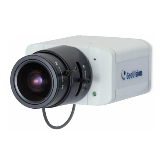
Page 18: Overview
2.4 Overview 2.4.1 GV-BX110D Figure 2-1 Name Description Audio Out Connects a speaker for audio output. Audio In Connects a microphone for audio input. I/O Terminal Block For details, see 2.7 I/O Terminal Block. Resets all configurations of the GV-IPCAM H.264 to the default factory settings. - Page 19 Box Camera Status LED The status LED is used to reflect the system status of the camera. Status LED Description Red Light ON The system powers on and succeeds to boot up. Flashing Red and The camera is ready for use with network Orange Lights connectivity.
-
Page 20: Gv-Bx120D / 220D / 320D
2.4.2 GV-BX120D / 220D / 320D Figure 2-2 Name Description Connects to a portable monitor for setting the focus and angle of Box Camera during Video Out initial installation. Inserts a micro SD/SDHC card to store Micro SD Card Slot recording data. -
Page 21: Focus Adjustment
Box Camera 2.5 Focus Adjustment There are two ways to access live images of the Box Camera for focus adjustment. One is to connect a portable monitor to the Video Out port on the rear panel of the Box Camera. The other is to connect the Box Camera to the network and access its live images. -
Page 22: Optional Installation
2.6 Optional Installation 2.6.1 C-Mount Lenses If you use the C-mount lens, it requires a certain distance from the camera’s imaging chip; otherwise it will not be possible to focus the lens. Mount the supplied C mount adapter to the camera, and then attach the lens onto the C-mount adapter. -
Page 23: Infrared Illuminators
Box Camera 2.6.2 Infrared Illuminators If you use the infrared (IR) illuminator with I/O function, follow the steps below to install it. Connect the infrared illuminator to the terminal block on the camera. See 2.7 The I/O Terminal Block. Access the Web interface of the camera. Select Video and Motion, select Video Settings, select Streaming 1 and set the IR Check Function option to be Trigger by Input. -
Page 24: I/O Terminal Block
Figure 2-3 Output N/O The GV-BX110D only supports the input device of Wet Contact, 7V ~ 30V. For the output point, please check if your output device meets the following Absolute Maximum Ratings before connecting it to the output point. - Page 25 Box Camera GV-BX120D / 220D / 320D The GV-BX120D / 220D / 320D support one digital input and one digital output. Function Digital Input Digital Output Figure 2-4 For details on how to enable an installed I/O device, see 9.2 I/O Settings.
-
Page 26: Chapter 3 Mini Fixed Dome
Chapter 3 Mini Fixed Dome The Mini Fixed Dome is a ceiling-mount device that provides panning and tilting functions. It features a built-in microphone and PoE connector. Its compact design ensures easy installation in almost any indoor environment. 3.1 Packing List •... -
Page 27: Options
Mini Fixed Dome 3.3 Options Optional devices can expand your Mini Fixed Dome’s capabilities and versatility. Contact your dealer for more information. The GV-PA191 is a Power over Ethernet (PoE) adapter designed to provide power to the IP device GV-PA191 through a single Ethernet cable. -
Page 28: Overview
3.4 Overview Figure 3-1 Name Description Resets the camera to factory default. See Default Button 9.3 Restoring to Factory Default Settings. Lens Rotates the les right/left to adjust focus. Focus Fixed Screw Loosens the screw to adjust the lens. Tilt Fixed Screw Loosens the screw to adjust tilt angle. -
Page 29: Focus Adjustment
Mini Fixed Dome 3.5 Focus Adjustment To produce a clear image, follow the steps below to adjust the camera’s focus. Unscrew the camera’s cover. Figure 3-3 Loosen the focus fixed screw, and rotate the lens clockwise or counterclockwise to adjust focus. Loosen the tilt fixed screw, and adjust the camera’s tilt angle. -
Page 30: Chapter 4 Bullet Camera
Chapter 4 Bullet Camera The Bullet Camera features a weather sealed and IP66 compliant housing for outdoor use. The camera also features IR LEDs for infrared illumination in night vision applications. 4.1 Packing List • Bullet Camera • Lens (Megapixel and Built-In 16 IR LEDs) •... -
Page 31: Features
Bullet Camera 4.2 Features • 1.3 megapixel progressive scan CMOS • Dual video streams from two of H.264, MJPEG and MPEG4 • Up to 15 fps at 1280 x 1024 • IP66 compliant • Cable-concealed bracket preventing cable from being cut •... -
Page 32: Options
4.3 Options Optional devices can expand your Bullet camera’s capabilities and versatility. Contact your dealer for more information. The GV-PA191 is a Power over Ethernet (PoE) adapter designed to provide power to the IP device GV-PA191 through a single Ethernet cable. -
Page 33: Installation
Bullet Camera 4.4 Installation These instructions describe the basic installation of the Bullet Camera. Slide the cable clamp to the camera base. Figure 4-1 Install the Bullet Camera to the wall. Figure 4-2... - Page 34 Install the related cables to the Bullet Camera. See 4.2.1 Connecting to the Data Cable. Adjust angles of the Bullet Camera. See 4.2.2 Adjusting Bullet Camera’s Angles. Remove the protection sticker from the camera’s cover. Figure 4-3 Loosen the camera’s cover, adjust lens and focus, and insert a micro SD card into the SD card slot.
-
Page 35: Connecting To The Data Cable
Bullet Camera 4.4.1 Connecting to the Data Cable With the 7-Pin Data Cable, you can connect the power, microphone, speaker and I/O devices to the Bullet Camera. The data cable is illustrated as below. Figure 4-4 I/O Wire Definition The I/O wires on the 7-Pin Data Cable can connect to 1 sensor input and 1 alarm output. - Page 36 Power Input Connection To connect the power, first you have to connect the unshielded black and brown wires of the Bullet Camera to the supplied 3-Pin Terminal Block, and then connect the 3-Pin Terminal Block to DC 12V Power Adapter. Insert the black wire of the Bullet Camera to the left-side pin of the 3- Pin Terminal Block and the brown wire to the right-side pin.
- Page 37 Bullet Camera Waterproof Treatment To install the Bullet Camera outdoors, ensure to waterproof the cables. The camera’s body is waterproof, but the PoE, audio, power and I/O cables are not waterproof. Use waterproof silicon rubber or the like to apply waterproof treatment to the cables.
-
Page 38: Adjusting Bullet Camera's Angles
4.4.2 Adjusting Bullet Camera’s Angles There are three shafts designed to adjust the Bullet Camera‘s angles. First Shaft You can adjust the camera body by 360 degrees to the right or the left. Unscrew the panning lock screw with the screw adjuster. Panning Lock Screw Screw Adjuster Figure 4-8... - Page 39 Bullet Camera Second Shaft You can adjust the camera body up and down by 90, 112.5, 135, 157.5 or 180 degrees by using the gears inside the camera body and the camera base. Unscrew the tilting lock screw with the screw adjuster. Figure 4-10 Hold the camera body, and move the camera base to the right to separate the camera gears.
- Page 40 Adjust the angle of camera body to 90, 112.5, 135, 157.5 or 180 degrees. Then move the camera base to the left to combine the gears. Figure 4-12 Fasten the tilting lock screw. Third Shaft You can adjust the camera base by 360 degrees. Unscrew the base fixing screw with the screw adjuster.
-
Page 41: Adjusting Lens And Inserting A Micro Sd Card
Bullet Camera Adjust the angle of camera base, and fasten the base fixing screw. Figure 4-14 4.4.3 Adjusting Lens and Inserting a Micro SD Card To adjust the camera’s lens to produce a clear image and insert a micro SD card into the SD card slot, follow the steps below. Loosen the camera’s cover. - Page 42 Remove the silica gel bag. Figure 4-16 Loosen the fixing screw. Figure 4-17...
- Page 43 Bullet Camera Slightly pull out the camera module. Loosen the Focus Adjustment Screw or the Zoom Adjustment Screw to rotate the lens right/left to adjust focus or zoom. Insert a micro SD card into the SD card slot. Figure 4-18 Slightly push the camera module back and fasten the fixing screw.
-
Page 44: Installing The Sun-Shield Cover
4.4.4 Installing the Sun-Shield Cover After setting up the Bullet Camera, now you can install the sun-shield cover to the camera. Fasten the hexagon screws either on top or below the camera. Figure 4-19 Put the sun-shield cover on top of hexagon screws. Make sure to aim the rear hexagon screw at the edge of the sun-shield cover’s aperture for optimal sun-shield performance. - Page 45 Bullet Camera Fasten the philips head screws with the plastic screw spacers. Figure 4-21...
-
Page 46: Chapter 5 Ptz Camera
Chapter 5 PTZ Camera The GV-PTZ010D camera is a ceiling-mount device that provides panning, tilting and zooming functions. The camera is designed to monitor a wide area and also to focus on a specific part on the live view when suspicious events occur. -
Page 47: Packing List
PTZ Camera 5.1 Packing List • GV-PTZ010D • Mounting base • Mounting cover • Wall mount bracket • Screw anchors • Long screws • Short screws • Round screws • DC 12V power adapter • Washers • • GV-PTZ010D software CD GV-PTZ110D / GV-PTZ010D Quick Start Guide... -
Page 48: Features
5.2 Features • 1/4" CCD image sensor • Dual streams from H.264, MJPEG and MPEG4 • Up to 30 fps at 704 x 480 / Up to 25 fps at 704 x 576 • 10x optical zoom lens • 10x digital zoom •... -
Page 49: Options
PTZ Camera 5.3 Options Optional devices can expand your PTZ camera’s capabilities and versatility. Contact your dealer for more information. The GV-PA191 is a Power over Ethernet (PoE) GV-PA191 adapter designed to provide power to the IP device through a single Ethernet cable. -
Page 50: Installation
5.4 Installation The GV-PTZ010D / GV-PT110D camera is designed for indoor usage. Please make sure that the installing location is shielded from rain and moisture. There are two ways to mount the PTZ / PT camera: Ceiling Mount and Wall Mount. Ceiling Mount Use the mounting base to make 3 marks on the wall for screw anchors. - Page 51 PTZ Camera Fix the mounting base (now with the PTZ / PT camera attached) to the wall with 3 long screws. Figure 5-3 Put on the mounting cover. To fit the installation environment, you can cut the parts indicated by arrows to make an opening for wires and cables.
-
Page 52: Wall Mount
Wall Mount You may wall-mount GV-PTZ010D / GV-PT110D camera with or without the mounting cover. Take the wall mount bracket and make 2 marks on the wall for screw anchors. Figure 5-5 Drill the marks and insert 2 screw anchors. Insert the long screws and leave enough distance (approximately 2 mm) to hang the wall mount bracket later. - Page 53 PTZ Camera Hang the wall mount bracket on the screws and push the wall mount bracket downward. Make sure the long screws are tightened. Figure 5-7 Without Mounting Cover Attach the wall mount bracket with the PTZ / PT camera using 3 washers and 3 round screws.
- Page 54 With Mounting Cover To install the mounting cover, attach the mounting base to the camera and then put on the mounting cover. See steps 3 and 5 in the Ceiling Mount section. Attach the wall mount bracket with the PTZ / PT camera using 3 round screws.
-
Page 55: Overview
PTZ Camera 5.5 Overview Figure 5-10... - Page 56 Name Description DC 12V / AC 24V Connects to a DV 12V or AC 24V Power Terminal Block Adapter. LAN/PoE Connects to a 10/100 Ethernet or PoE. I/O Terminal Block For details, see 5.6 I/O Terminal Block. Inserts a micro SD/SDHC card to store Micro SD Card Slot recording data.
-
Page 57: Focus Adjustment
PTZ Camera 5.6 Focus Adjustment On initial installation, it is advised that you adjust the focus for image clarity. Print out the diagram of radiating lines included on Software CD and hang up the diagram at the surveillance area. Use the Zoom In / Out and Focus In / Out buttons on the PTZ control panel from the Web interface (No.4 and 5, Figure 5-12) and adjust the PTZ camera until it displays clear radiating lines as shown in picture on the left. -
Page 58: I/O Terminal Block
5.7 I/O Terminal Block The 3-pin terminal block, located on the back panel of the PTZ camera, provides the interface to one digital input and one digital output. The I/O terminal block can be used to develop applications for motion detection, event alerts via E-Mail and FTP, and center monitoring through Center V2 and VSM. -
Page 59: Ptz Control
PTZ Camera 5.8 PTZ Control After you have installed the PTZ camera on network and accessed the camera’s Web interface you are ready to configure the PTZ camera. To see how to install the PTZ camera on network, see Getting Started, Chapter 7. - Page 60 Buttons on the PTZ control panel: Name Description Exit Closes the PTZ control panel. Moves the PTZ camera to 8 directions: up, Pan / Tilt Control down, left, right, left up, left down, right up and right down. Brings the camera view back to the home Home point where the camera faces front at a 90 degree angle to the base of the device.
-
Page 61: Automatic Focus
PTZ Camera 5.8.2 Automatic Focus When the camera view is fuzzy, you may use the auto focus feature to obtain a sharper view. On the PTZ control panel, click the Option button (No. 6, Figure 5-12) and select AF for automatic focus. 5.8.3 PTZ Camera Settings Accessing the PTZ Camera Settings To access PTZ camera settings, click the Option button (No. - Page 62 PT Speed: Determines the panning (horizontal movement) and tilting (vertical movement) speed when using the Pan / Tilt Control buttons on the PTZ control panel. The drop-down list contains 5 speed settings: 1 is the slowest and 5 the fastest. Zoom Speed: Determines the zooming speed.
-
Page 63: Image Settings
PTZ Camera 5.8.4 Image Settings Image Setting provides features on iris control, white balance, image orientation and other image processing tools to generate clearer images. To access these features, open the VISCA OSD Configuration dialog box and select Image Setting. [Iris] adjusts the amount of exposure. - Page 64 fixed light source. Use the slider to select from 0 to 8. A higher value produces a brighter image and a lower value produces a dimmer image. R Gain: Adjusts the red element of the live view. Use the slider to select from 0 to 8.
- Page 65 PTZ Camera Freeze: Instantly freezes the live view image when On is selected. AGC: Automatic Gain Control (AGC) utilizes an electronic circuit which amplifies video signal when the signal strength falls below a given value due to lack of the light on the camera. Adjust camera sensitivity to provide clear images.
-
Page 66: Preset Settings
5.8.5 Preset Settings For PTZ camera to automatically move toward a point in live view, establish a Preset. A Preset is a point in live view that can be configured and saved for future use. The PTZ camera allows up to 256 Preset points. For details on the maximum number of Preset points, see 5.7.3 PTZ Camera Settings. - Page 67 PTZ Camera Renaming a Preset Point To rename a Preset point: Click the Option button (No. 6, Figure 5-12), select Preset Set and select Naming. The dialog box appears. Figure 5-15 Click the Preset point you wish to rename and type the new name in the blank at the top.
- Page 68 Starting and Stopping a Preset Point To start a Preset movement, click the Option button (No. 6, Figure 5-12), select Preset Go, and select a Preset number which has been set previously. Alternatively, you may use the number pad on the PTZ control panel to enable a Preset movement: Click the Show Preset button (No.
-
Page 69: Sequence Settings
PTZ Camera 5.8.6 Sequence Settings For PTZ camera to automatically perform a series of movements, you can configure a Sequence. A Sequence links up more than two Preset points to form a sequence of movements. Up to 8 Sequences can be created. Configuring a Sequence After you have configured the Preset points you wish the camera to follow (for details, see 5.7.5 Preset Settings), you are ready to... - Page 70 Use the Preset drop-down list to select the Preset points for the Sequence. Use the Dwell Time drop-down list to select the staying time that the camera stays at the Preset point. The dwell time ranges from 0 to 127 seconds at an interval of 0.5 second.
-
Page 71: Auto Pan Settings
PTZ Camera 5.8.7 Auto Pan Settings For the PTZ camera to survey a horizontal view, establish an Auto Pan. Up to 4 sets of Auto Pan can be created. Configuring an Auto Pan To configure a horizontal movement: Adjust the angle of the camera view using the Up and Down Control buttons since any vertical movements of the camera will not be recorded by Auto Pan. - Page 72 Configuring the Speed of Auto Pan You can configure the speed for each set of Auto Pan differently: Open the VISCA OSD Configuration dialog box and select Advance. Figure 5-17 Select the Auto Pan number you wish to configure and select the Speed.
-
Page 73: Rebooting The Camera
PTZ Camera Starting and Stopping Autopan To start an Auto Pan, click the Option button (No. 6, Figure 5-12), select Auto and select a desired Auto Pan number. The PTZ camera will first return to the starting position of the selected Auto Pan and proceeds with the selected Auto Pan movement. -
Page 74: System Configuration
5.8.8 System Configuration To configure lens settings, open the VISCA OSD Configuration dialog box and select System Configure. Figure 5-18 Zoom + AF: Automatically focuses after zooming. It is advised to use this feature with a zooming distance of at least 1 meter. Digital Zoom: Allows up to 10x Digital Zoom. -
Page 75: Chapter 6 Pt Camera
PT Camera Chapter 6 PT Camera The GV-PT110D camera is a ceiling-mount device that features panning and tilting functions. The GV-PT110D is designed to monitor a wide area and to focus on a selected point on live view when suspicious events occur. 6.1 Packing List •... -
Page 76: Features
• DC 12V power adapter • Washers • GV-PT110D software CD GV-PTZ110D / GV-PTZ010D Quick Start Guide 6.2 Features • 1.3 megapixel progressive scan CMOS • Dual streams from H.264, MJPEG and MPEG4 • Up to 15 fps at 1280 x 1024 •... -
Page 77: Options
PT Camera 6.3 Options Optional devices can expand your PT camera’s capabilities and versatility. Contact your dealer for more information. The GV-PA191 is a Power over Ethernet (PoE) adapter designed to provide power to the IP device GV-PA191 through a single Ethernet cable. 6.4 Installation For installation procedures of the GV-PT110D, see 5.3 Installation. -
Page 78: Overview
6.5 Overview Figure 6-1... - Page 79 PT Camera Name Description DC 12V / AC 24V Connects to a DV 12V or AC 24V Power Terminal Block Adapter LAN/PoE Connects to a 10/100 Ethernet or PoE. I/O Terminal Block For details, see 5.6 I/O Terminal Block. Inserts a micro SD/SDHC card to store Micro SD Card Slot recording data.
-
Page 80: Focus Adjustment
6.6 Focus Adjustment On initial installation, it is advised that you adjust the focus for image clarity. Print out the diagram of radiating lines included on Software CD and hang up the diagram at the surveillance area. Manually adjust the focus by rotating the focus ring (No. -
Page 81: I/O Terminal Block
PT Camera 6.7 I/O Terminal Block The 3-pin terminal block, located on the back panel of the PT camera, provides the interface to one digital input and one digital output. The I/O terminal block can be used to develop applications for motion detection, event alerts via E-Mail and FTP, and center monitoring through Center V2 and VSM. -
Page 82: Pt Control
6.8 PT Control The GV-PT110D shares similar user interfaces and features with the GV- PTZ010D camera. The supported functions are listed in the table below. Supported Function Description PT Control Panel The following buttons on the PT control panel are available: Exit, Pan / Tilt Control, Home, Option and Show Preset. - Page 83 PT Camera Figure 6-3 Figure 6-4...
- Page 84 Figure 6-5...
-
Page 85: Chapter 7 Getting Started
Getting Started Chapter 7 Getting Started This section provides basic information to get the GV-IPCAM H.264 working on the network. 7.1 Installing on a Network These instructions describe the basic connections to install the GV-IPCAM H.264 on the network. Use a standard network cable to connect the camera to your network. Optionally connect a speaker and a microphone for two-way audio communication. -
Page 86: Assigning An Ip Address
7.2 Assigning an IP Address Designed for use on the network, the GV-IPCAM H.264 must be assigned an IP address to make it accessible. Note: The camera has a default IP address of 192.168.0.10. The computer used to set the IP address must be under the same network assigned to the unit. -
Page 87: Getting Started
Getting Started Select Static IP address. Type IP Address, Subnet Mask, Router/Gateway, Primary DNS and Secondary DNS in the Configure connection parameters section. Click Apply. The camera is now accessible by entering the assigned IP address on the web browser. Important: Dynamic IP Address and PPPoE should only be enabled if you know which IP address the camera will get from the DHCP server... -
Page 88: Configuring The Basics
7.3 Configuring the Basics Once the camera is properly installed, the following important features can be configured using the browser-based configuration page and are discussed in the following sections in this manual: • Date and time adjustment: see 9.8.1 Date & Time Setting. •... -
Page 89: Chapter 8 Accessing The Camera
Accessing the Camera Chapter 8 Accessing th e Camera Two types of users are allowed to log on to the GV-IPCAM H.264: Administrator and Guest. The Administrator has unrestricted access to all system configurations, while the Guest has the acc ess to live view and network status only. - Page 90 Click Apply. A video image, similar to the example on Figure 8-2, is now displayed in your browser. Note: To enable the updating of images in Internet Explorer, you must set your browser to allow ActiveX Controls and perform a once-only installation of GeoVision’s ActiveX component onto your computer.
-
Page 91: Functions Featured On The Main Page
Accessing the Camera 8.2 Functions Featured on the Main Page This section introduces the features of the Live View window and Network Status on the main pag e. The two features are accessible by both Administrator and Guest. Main P age of Guest Mode ▼... -
Page 92: The Live View Window
8.2.1 The Live View Window Figure 8-3 No. Name Function 1 Play Plays live video. 2 Stop Stops playing video. Talks to the surveillance area from the local 3 Microphone computer. 4 Speaker Listens to the audio around the camera. Takes a snapshot of live video. - Page 93 Accessing the Camera --- See 8.2.4 Video Recording. Switches to full screen vie w. Right-click the image to have these optio ns: Snapshot, Full Screen, Resoluti on, Zoom In, Zoom Out, PIP, 7 Full Scree PAP and Google Maps. --- See 8.2.5 Picture-in- Picture and Picture-and- Picture View for PIP an d PAP views,...
-
Page 94: The Control Panel Of The Live View Window
8.2.2 The Control Panel of the Live View Window To open the control panel of the Live View window, click the arrow button on top of the window. You can access the following functions by using the right and left arrow buttons on the control panel. Figure 8-4 [Information] Displays the version of the camera, time of the local computer, time of the camera (host time), the number of users logging in... - Page 95 Accessing the Camera [Alarm Notify] Displays the captured images by sensor triggers and motion detection. For this function to work, you ha ve to configure the Alarm Notify settings first. See 8.2.6 Alarm Notificatio [Camera Adjustment] Allows you to adjust the image quality settings. Note that the GV-PTZ010D only contains the Gamma and Image Orientation functions and the Saturation function is only available in BX110D, MFD110D, BL110D and PT110D.
- Page 96 Brightness: Adjusts the brightness of the image. Contrast: Adjusts the relative di fferences between one pixel and the next. Saturation: Adjusts the saturation of the ima Sharpness: Adjusts the sharpness of the imag Gamma: Adjusts the relative proportions of brigh t and dark areas White balance: The camera automatically adjus ts the color to be...
-
Page 97: Snapshot Of Live Video
Accessing the Camera [GPS] For details 9.8.2 GPS Map Settings. [Download] Allows you to i nstall the programs from the hard drive. 8.2.3 Snapshot of Live Video To take a snapshot of live video, follow these step Click the Snapshot button (No. 5, Figure 8-3). -
Page 98: Picture-In-Picture And Picture-And-Picture View
8.2.5 Picture-in-Picture and Picture-an d-Picture View The full screen mode provides two types of close-u p views: Picture-in- Picture (PIP) a nd Picture-and Picture (PAP). The two views are useful to provide clear and detailed images of the surveillan ce area. To access this feature: •... - Page 99 Accessing the Camera Picture-and-Picture View With the Picture and Picture (PAP) view, you can create a split video effect with multiple close-up views on the image. A total of 7 close-up views can be defined. Figure 8-7 Select PAP. A row of three inset windows appe ars at the bottom.
- Page 100 To delete a navigation box, right-click the desired box, select Focus Area of PAP Mode and click Delete. To exit the PAP view, right-click the image and click PAP again.
-
Page 101: Alarm Notification
Accessing the Camera 8.2.6 Alarm Notification After input triggers and motion detection, you can be alerted by a pop-up live video and view up to four captured images. Pop-up live Captured video images video Figure 8-8 To configure this function, click the Show System Menu button (No. 10, Figure 8-3), and select Alarm Notify. - Page 102 For this function to work, the Administrator needs to install the input erly. See 9.2.1 Input Setting. device prop Alert Sound: Activates the computer alarm on motion and input- triggered detection. IE Window Pops up: The minimized Live View window pops up on motion and input-triggered detection.
-
Page 103: Video And Audio Configuration
Accessing the Camera 8.2.7 Video and Audio Configura tion You can enable the microphone and speaker for two-way audio communication and adjust the audio volume. To change audio configuration, click the Show System Menu button (No. 10, Figure 8-3), and select Video and Audio Configuration. Figure 8-10... -
Page 104: Remote Configuration
8.2.8 Remote Configuration You can view the connection status of the central monitoring stations and upgrade firmware over the Internet. Click the Show System Menu button (No. 10, Figure 8-3), and select Remote Config. T he Remote Config dialog box will appear. [Status] In this tab, you c an see the current status of the connection to Center V2 and VSM. -
Page 105: Visual Ptz
Accessing the Camera 8.2.11 Visual PTZ Note this feature is only available in PTZ Camera and PT Camera. The Visual PTZ prov ides two types of PTZ control panels on live images for easy and direct PTZ operation. Activating Visual PTZ Click the PTZ Control button (No. - Page 106 Figure 8-13 The Visual PTZ Panel provides the following fea tures: Name Description Shortens the apparen t distance between the m In camera and the view Lengthens the appare nt distance between the Zoom O camera and the view. Focus In Adjusts the sharpness of the camera view.
- Page 107 Accessing the Camera points in live view. Starts a horizontal movement of the PTZ Auto Pan camera in live view. Setting Visual PTZ Panel Click the .button on the top left corner and se lect Visual PTZ, the following options will appear. PTZ Control Type: Two types of visual PTZ control panels are available.
-
Page 108: I/O Control
8.2.12 I/O Control Note this function is not available for Mini Fixed D ome. The I/O Control window provides a real-time graphic display of camera status, I/O status, and alarm events. Additionally, you can remotely force output to be triggered. Figure 8-14 •... -
Page 109: Visual Automation
Accessing the Camera 8.2.13 Visual Automation Note this function is only available for Box Cam era and Bullet Camera. The Visual Automation allows you to change the c urrent state of the electronic device by simply clicking on its image, e.g. turning the light ON. This feature is only available when the Visual Automation is set ahead by the Administrator. -
Page 110: Network Status
8.2.14 Network Status To view the network status, in the left menu, click Network and select Status. Figure 8-16... -
Page 111: Chapter 9 Administrator Mode
Administrator Mode Chapter 9 Administrator Mode The Administrator can access the system configuration through the network. Eight categories of configurations are involved in the system configuration: Video and Motion, I/O Control or Digital I/O and PTZ, Events and Alerts, Monitoring, Recording Schedule, Remote ViewLog, Network and Management. - Page 112 List of Menu Options Find the topic of interest by referring to the section number prefixed to each option. The available options vary among camera models. 9.1.1 Video Settings 9.1.2 Motion Detection 9.1.3 Privacy Mask 9.1 Video and Motion 9.1.4 Text Overlay 9.1.5 Tampering Alarm 9.1.6 Visual Automation 9.2.1 Input Settings...
-
Page 113: Video And Motion
Administrator Mode 9.1 Video and Motion The GV-IPCAM H.264 can process one video stream in two different codec and image settings. Two setting pages Streaming 1 and Streaming 2 are provided for separate setup. Comparison between Streaming 1 and Streaming 2: Video Setting Options Streaming 1 Streaming 2... -
Page 114: Video Settings
9.1.1 Video Settings Figure 9-2... - Page 115 Rate 1280 x 960 15 fps 640 x 480 30 fps 320 x 240 Main 1280 x 1024 15 fps GV-BX110D 640 x 512 GV-MFD110D 320 x 256 GV-BL110D 640 x 480 30 fps 320 x 240 640 x 512...
- Page 116 640 x 480 320 x 240 640 x 360 16:9 448 x 252 640 x 512 320 x 256 1600 x 1200 1280 x 960 640 x 480 320 x 240 1920 x 1080 Main 1280 x 720 16:9 640 x 360 448 x 252 1280 x 1024 GV-BX220D...
- Page 117 Administrator Mode 2048 x 1536 20 fps 1600 x 1200 1280 x 960 640 x 480 320 x 240 1920 x 1080 Main 1280 x 720 16:9 640 x 360 448 x 252 GV-BX320D 1280 x 1024 30fps 640 x 512 320 x 256 640 x 480 320 x 240...
- Page 118 1280 x 960 15 fps 640 x 480 30 fps 320 x 240 Main 1280 x 1024 15 fps 640 x 512 GV-PT110D 320 x 256 640 x 480 4: 3 30 fps 320 x 240 640 x 512 5: 4 320 x 256 Note: The frame rate and the performance may vary depending on the number of connections and data bitrates (different scenes)
- Page 119 Administrator Mode [Bandwidth Management] When using H.264 or MPEG4 it is possible to control the bitrate, which in turn allows the amount of bandwidth usage to be controlled. VBR (Variable Bitrate): The quality of the video stream is kept as constant as possible at the cost of a varying bitrate.
- Page 120 Overlaid with camera name: Includes streaming names on live and recorded videos. Overlaid with date stamps: Includes date stamps on live and recorded videos. Overlaid with time stamps: Includes time stamps on live and recorded videos. Overlaid with digital input description: Includes the name of the selected input on live and recorded videos.
- Page 121 Administrator Mode [Mechanical Iris Adjustment] Auto adjustment: The option is designed for auto iris lens (DC drive). Click Start to automatically adjust the auto iris lens and bring exposure to optimum. For the first-time user of auto iris lens, you must enable this option to make adjustment for the lens and re-log on to the camera.
- Page 122 Auto Iris: The option is designed for auto iris lens (DC drive). Enable the auto iris function when the scene appears fuzzy and the Flicker Less function does not help to improve the situation.
-
Page 123: Motion Detection
Administrator Mode 9.1.2 Motion Detection Motion detection is used to generate an alarm whenever movement occurs in the video image. You can configure up to 8 areas with different sensitivity values for motion detection. Figure 9-3 The default sensitivity value for the whole area is 2. To define a different sensitivity value, click Reset. -
Page 124: Privacy Mask
9.1.3 Privacy Mask The Privacy Mask can block out sensitive areas from view, covering the areas with dark boxes in both live view and recorded clips. This feature is ideal for locations with displays, keyboard sequences (e.g. passwords), and for anywhere else you don’t want sensitive information visible. Figure 9-4 Select the Enable option. -
Page 125: Text Overlay
Administrator Mode 9.1.4 Text Overlay Note this function is only available in Box Camera, Mini Fixed Dome and Bullet Camera. The Text Overlay allows you to type any text in any place on the camera view. Up to 16 text messages can be created on one camera view. The overlaid text will be saved in the recordings. -
Page 126: Tampering Alarm
9.1.5 Tampering Alarm Note this function is only available for Box Camera, Mini Fixed Dome and Bullet Camera. The Tampering Alarm is used to detect when a camera is being physically tampered. An alarm can be generated when the camera is moved, covered up, or out of focus. - Page 127 Administrator Mode To configure the tampering alarm: Select the Enable option. If you want the camera to ignore any movement or scene change in certain areas, click the button to drag areas on the camera view. Select the desired detection sensitivity by moving the slider. The higher the value, the more sensitive the camera is to scene changes.
-
Page 128: Visual Automation
9.1.6 Visual Automation Note this function is only available for Box Camera and Bullet Camera. This intuitive feature helps you automate any electronic device by triggering the connected output device. When you click on the image of the electronic device, you can simply change its current state, e.g. light ON. Figure 9-8 Select the Enable option. -
Page 129: I/O Settings
Administrator Mode 9.2 I/O Settings Note the I/O function is only available for Box Camera, Bullet Camera, PTZ Camera and PT Camera. After installing the I/O device, you need to enable the I/O settings on the camera. For how to install the I/O device on the camera, see the following reference sections: GV-IPCAM H.264 Reference section... - Page 130 Normal State: You can set the input state to trigger actions by selecting Open Circuit (N/O) or Grounded Circuit (N/C). Latch Mode: Enable this option to have a momentary output alarm. Trigger digital output relay: When this option is enabled, the output will be triggered once the input is activated.
-
Page 131: Output Settings
Administrator Mode 9.2.2 Output Settings Select Enable to start the output device. Choose the output signal that mostly suits the device you are using: N/O (Open Circuit), N/C (Grounded Circuit), N/O Toggle, N/C Toggle, N/O Pulse or N/C Pulse. For Toggle output type, the output continues to be triggered until a new input trigger ends the output. -
Page 132: Ptz Settings
9.2.3 PTZ Settings Note this function is only available in PTZ Camera and PT Camera. You can change the image settings, configure sequences, and access settings including autopan speed, motor reset, digital zoom and system default loading. For details, see Accessing the VISCA OSD Configuration in 5.7.3 PTZ Camera Settings. -
Page 133: Events And Alerts
Administrator Mode 9.3 Events and Alerts For the events of motion detection or I/O trigger, the Administrator can set up two trigger actions: 1. Send a captured still image by E-mail or FTP. 2. Notify Center Monitoring Station, Center V2 or VSM, by video or text alerts. -
Page 134: E-Mail
9.3.1 E-mail After a trigger event, the camera can send the e-mail to a remote user containing a captured still image. Figure 9-13 [Enable] Select to enable the e-mail function. Sever URL/IP Address: Type the URL address or IP address of the SMTP Server. - Page 135 Administrator Mode [Need authentication to login] If the SMTP Server needs authentication, enable this option and type a valid username and password to log in the SMTP server. [E-Mail Alarm Settings] You can choose to automatically send an e-mail alert under these conditions: tampering alarm (not available for PTZ and PT Camera), disk write error (Rec Error), hard disk full (HD Full) and motion detection.
-
Page 136: Ftp
9.3.2 FTP You can also send the captured still image to a remote FTP server for alerts. Figure 9-14 [Upload to an FTP Server] Enable: Select to enable the FTP function. Server URL/IP Address: Type the URL address or IP address of the FTP Server. - Page 137 Administrator Mode Alerts Interval time in minute: Specify the interval between FTP alerts. The interval can be between 0 and 60 minutes. The option is useful for the frequent event occurrence by which any event triggers during the interval period will be ignored. [Alarm Settings] Motion Detection: When a motion is detected on the camera, a still image will be sent to the FTP Server.
-
Page 138: Center V2
9.3.3 Center V2 After a motion or an I/O triggered event, the central monitoring station Center V2 can get notified by live videos and text alerts. For the live monitoring through Center V2, you must already have a subscriber account on Center V2. - Page 139 Administrator Mode To enable the Center V2 connection: 1. Activate Link: Enable the monitoring through Center V2. 2. Host Name or IP Address: Type the host name or IP address of Center V2. 3. Port Number: Match the port to the Port 2 value on Center V2. Or keep the default value 5551.
-
Page 140: Vsm
9.3.4 VSM After a motion or an I/O triggered event, the central monitoring station VSM can get notified by text alerts. For the monitoring through VSM, you must already have a subscriber account on VSM. A camera can connect up to 2 VSM simultaneously. - Page 141 Administrator Mode Host Name or IP Address: Type the host name or IP address of VSM. Port Number: Match the port to the Port 2 value on VSM. Or keep the default value 5609. User Name: Type a valid username to log into VSM. Password: Type a valid password to log into VSM.
-
Page 142: Backup Center
9.3.5 Backup Center Note this function is only available for Box Camera and Bullet Camera. The connection to the GV-Backup Center allows you to back up another copy of recordings and system log to the GV-Backup Center while the camera is saving these data to the memory card. Figure 9-17... - Page 143 Administrator Mode To enable the GV-Backup Center connection: Activate Link: Enable the connection to the GV-Backup Center. Host Name or IP Address: Type the host name or IP address of the GV-Backup Center. Port Number: Match the communication port on the GV-Backup Center.
-
Page 144: Viewlog Server
9.3.6 ViewLog Server Note this feature is only available for Box Camera, Bullet Camera, PTZ Camera and PT Camera. The ViewLog Server is designed for remote playback function. This server allows you to remotely access the recorded files saved at the GV-IPCAM H.264 and play back video with the ViewLog player. -
Page 145: 3Gpp
Administrator Mode 9.3.7 3GPP The 3GPP Server enables video and audio streaming to your 3G-enabled mobile phone. Figure 9-19 Activate Link: Enable the 3GPP service. RTSP/TCP Port: Keep the default value 8554, or modify it if necessary. RTP/UDP Port: Keep the default range from 17300 to 17319, or modify it if necessary. -
Page 146: Monitoring
9.4 Monitoring You can start monitoring manually, by schedule or by input trigger. Note: See Note for Recording at the beginning of the manual. Figure 9-20 [Manual] Manually activates motion detection and I/O monitoring. Select one of the following options and then click the Start button. Select all: Manually starts both motion detection and I/O monitoring. - Page 147 Administrator Mode [Camera Status Icon] : On standby : Enabled for motion detection and input trigger...
-
Page 148: Recording Schedule
9.5 Recording Schedule The schedule is provided to activate recording and I/O monitoring on a specific time each day. 9.5.1 Recording Schedule Settings You can set the schedule for recording. Figure 9-21 Span 1- Span 3: Set a different recording mode for each time frame during the day. -
Page 149: I/O Monitoring Settings
Administrator Mode 9.5.2 I/O Monitoring Settings Note this function is only available for Box Camera, Bullet Camera, PTZ Camera and PT Camera. You can set the schedule for I/O monitoring to start. Figure 9-22 Span 1- Span 3: Set different time frames during the day to enable I/O monitoring. -
Page 150: Remote Viewlog
9.6 Remote ViewLog Note this function is only available for Box Camera, Bullet Camera, PTZ Camera and PT Camera. With the Remote ViewLog function, you can play back the files recorded at the GV-IPCAM H.264 over TCP/IP network. For the first-time user, you need to install the Remote ViewLog program from the Software DVD. -
Page 151: Network
Administrator Mode 9.7 Network The Network section includes some basic but important network configurations that enable the camera to be connected to a TCP/IP network. 9.7.1 LAN According to your network environment, select among Static IP, DHCP and PPPoE. Figure 9-23... - Page 152 [LAN Configuration] Dynamic IP address: The network environment has a DHCP server. This option should only be enabled if you know which IP address the camera will get from the DHCP server, or you have obtained a domain name from the DDNS service provider that always links to the camera’s changing IP address.
-
Page 153: Advanced Tcp/Ip
Administrator Mode 9.7.2 Advanced TCP/IP This section introduces the advanced TCP/IP settings, including DDNS Server, HTTP port, streaming port and UPnP. Figure 9-24 [Dynamic DNS Server Settings] DDNS (Dynamic Domain Name System) provides a convenient way of accessing the camera when using a dynamic IP. - Page 154 Before enabling the following DDNS function, the Administrator should have applied for a Host Name from the DDNS service provider’s website. There are 2 providers listed in the camera: GeoVision DDNS Server and DynDNS.org. To enable the DDNS function: 1. Enable: Enable the DDNS function.
-
Page 155: Ip Filter Settings
Administrator Mode 9.7.3 IP Filter Settings The Administrator can set IP filtering to restrict access to the camera. Figure 9-25 To enable the IP Filter function: Enable IP Filtering: Enable the IP Filter function. Filtered IP: Type one IP address or a range of IP addresses you want to restrict the access. -
Page 156: Management
9.8 Management The Management section includes the settings of data and time and user account. You can also view the firmware version and execute certain system operations. 9.8.1 Date & Time Settings The date and time settings are used for date and time stamps on the image. Figure 9-26... - Page 157 Administrator Mode [Date & Time on GV-IP Camera] Displays the current date and time on the camera. [Time Zone] Sets the time zone for local settings. Select Enable Daylight Saving Time to automatically adjust the camera for daylight saving time. Type the Start Time and End Time to enable the daylight saving function.
-
Page 158: Gps Maps Settings
9.8.2 GPS Maps Settings The Maps Settings allows you to see the location of your GV-IPCAM H.264 on Google maps, without a GPS device. To see the location of your camera on maps: It is required to sign up for a Google Maps API key before using the Google Maps. - Page 159 Administrator Mode Click Open. A warning message appears. Figure 9-29 Right-click the warning message and select Allow Blocked Content. The map will be displayed. The icon indicates the location of your camera. At the upper right corner you have options to view different map formats, such as Satellite and Hybrid.
-
Page 160: Storage Settings
9.8.3 Storage Settings Note this function is only available for Box Camera, Bullet Camera, PTZ Camera and PT Camera. Based on Linux ext3 file system, the GV-IPCAM H.264 supports memory cards for video and audio recordings. You need to format the memory card by using the following Storage Settings. -
Page 161: Disk Information
Administrator Mode [Disk Information] This section shows the details of the attached storage device. [Partition Information] This section shows the partition details of the attached storage device. To add a memory card: Insert the memory card to the camera. Click the Format button. After the format is complete, the partition information will display. -
Page 162: User Account
9.8.4 User Account You can change the login name and password of Administrator and Guest. The default Administrator login name and password are admin; the default Guest login name and password are guest. To allow a Guest user log in without entering name and password, select Disable authentication for guest account. -
Page 163: Log Information
Administrator Mode 9.8.5 Log Information The log information contains dump data that is used by service personnel for analyzing problems. Figure 9-33... -
Page 164: System Log
9.8.6 System Log Note this function is only available for Box Camera and Bullet Camera. The System Log records the events in the four types of logs: System Event, Monitoring Event, I/O Event and Login/Logout. With the System Log, you can search and obtain the detailed information of an event. To use the System Log, a memory card is required to insert to the camera. - Page 165 Administrator Mode Click Query. The filtering results may look like the figure below. Figure 9-35...
-
Page 166: Tools
9.8.7 Tools You can execute certain system operations and view the firmware version. Figure 9-36 [Host Settings] Enter a descriptive name for the camera. [Firmware Update] This field displays the firmware version of the camera. [System Settings] Load Default: Clicking the Load Default button to restore factory default settings. - Page 167 Administrator Mode Current Chipset Temperature inside the Camera: For Bullet Camera, PTZ Camera and PT Camera only. Displays the chipset temperature inside the camera. [Reboot] Clicking the Reboot button will make the camera perform software reset.
-
Page 168: Chapter 10 Recording And Playback
Chapter 10 Recording and Playback Note this chapter and the function is only available for Box Camera, Bullet Camera, PTZ Camera and PT Camera. The GV-IPCAM H.264 can record video and audio directly to the memory card. You can play back the recorded files on the GV-System or over the TCP/IP network. -
Page 169: Playback
Recording and Playback 10.2 Playback These methods are available to play back the video files recorded at the GV-IPCAM H.264: • Playback by using the memory card by connecting it directly to the GV-System through a memory card reader • Playback by using the Remote ViewLog function over the TCP/IP network •... - Page 170 Run ViewLog. Click the Advanced button , select Reload Database and click Video Server/Compact DVR. This dialog box appears. Figure 10-2 Click Add to assign the hard drive. Click OK to load the data to the ViewLog for playback.
-
Page 171: Playback Over Network
Recording and Playback 10.2.2 Playback over Network With the Remote ViewLog function, you can play back the files recorded at the GV-IPCAM H.264 over TCP/IP network. The camera needs to allow the remote access with ViewLog Server activated. See 9.3.6 ViewLog Server. For the first-time user, run the Remote ViewLog program from the Software CD. -
Page 172: Access To The Recorded Files Through Ftp Server
10.2.3 Access to the Recorded Files through FTP Server The built-in FTP Server allows you to download the recorded files saved on the memory card. You can play back the downloaded files of AVI format with any multimedia player. For details to download files, see [Act as FTP Server], 9.3.2 FTP. - Page 173 Recording and Playback On the Date Tree, select the date of Daylight Saving Time. A separate DST subfolder will be displayed as illustrated below. Figure 10-4 On the Video Event list, select desired events, and click the Play button to start. Note: The playback function is only compatible with the GV-System of version 8.3 and later.
-
Page 174: Chapter 11 Advanced Applications
WARNING: The interruption of power supply during updating causes not only update failures but also damages to the camera. In this case, please contact your sales representative and send your device back to GeoVision for repair. -
Page 175: Using The Web Configuration Interface
Advanced Applications 11.1.1 Using the Web Configuration Interface In the Live View window, click the Show System Menu button (No. 8, Figure 8-3), select Remote Config, and click the Firmware Upgrade tab. This dialog box appears. Figure 11-1 Click the Browse button to locate the firmware file (.img) saved at your local computer. -
Page 176: Using The Ip Device Utility
11.1.2 Using the IP Device Utility The IP Device Utility provides a direct way to upgrade the firmware to multiple units of GV-IPCAM H.264. Note the computer used to upgrade firmware must be under the same network of the camera. Insert the Software CD, select IP Device Utility, and follow the onscreen instructions to install the program. - Page 177 Advanced Applications Double-click one camera in the list. This dialog box appears. Figure 11-3 Click the Firmware Upgrade tab. This dialog box appears. Figure 11-4 Click the Browse button to locate the firmware file (.img) saved at your local computer. If you like to upgrade all the cameras in the list, select Upgrade all devices.
-
Page 178: Backing Up And Restoring Settings
11.2 Backing Up and Restoring Settings With the IP Device Utility included in the Software CD, you can back up the configurations in the GV-IPCAM H.264, and restore the backup data to the current camera or import it to another camera. To back up the settings: Run IP Device Utility and locate the desired camera. - Page 179 Advanced Applications To restore the settings: In Figure 11-3, click the Import Settings tab. This dialog box appears. Figure 11-6 Click the Browse button to locate the backup file (.dat). Select Upgrade all devices to import the settings into the same type of device in the same LAN.
-
Page 180: Restoring To Factory Default Settings
Please refer to the corresponding section of your camera type and follow the steps to restore factory default settings. Box Camera: GV-BX110D Unplug the power cable and the network cable to start. Press and hold the Default button (No. 4, Figure 2-1) on the back panel of the camera. - Page 181 Advanced Applications Mini Fixed Dome: Unplug the network cable to start. Unscrew the camera’s cover. Press and hold the Default button (No. 1, Figure 3-1). Plug the network cable to power on the camera through the PoE adaptor. Wait until the network status LED turns off. This may take about 40 seconds.
- Page 182 PTZ and PT Camera There are two types of default settings: camera default settings and system default settings. Camera default settings include all settings on Iris, White Balance, Image Reverse and Other in the VISCA OSD Configuration dialog box (Figure 5-14). System default settings refer to all the settings of the PTZ / PT camera except the camera settings.
- Page 183 Advanced Applications To load system default settings Unplug the power cable or the network cable (if it is also used as the power supply). Press and hold the Default button (No. 10, Figure 5-10). Plug the power and network cable back. Hold the Default button until the two network LEDs fade.
-
Page 184: Verifying Watermark
11.4 Verifying Watermark The watermark is an encrypted and digital signature embedded in the video stream during the compression stage, protecting the video from the moment of creation. Watermarking ensures that an image is not edited or damaged after it is recorded. To enable the watermark function, see [Watermark Setting], 9.1.1 Video Settings. -
Page 185: Running Watermark Proof
Advanced Applications 11.4.2 Running Watermark Proof Install Watermark Proof from the Software CD. After installation, a WMProof icon is created on your desktop. Double-click the created icon. The Water Mark Proof window appears. Click File from the menu bar, select Open and locate the recording (.avi). -
Page 186: The Watermark Proof Window
11.4.3 The Watermark Proof Window Figure 11-10 The controls in the window: No. Name Description Open File Opens the recording. First Frame Goes to the first frame of the file. Play Plays the file. Previous Frame Goes to the previous frame of the file. Next Frame Goes to the next frame of the file. -
Page 187: Chapter 12 Dvr Configurations
DVR Configurations Chapter 12 DVR Configurations The GV-System provides hybrid solution, integrating the digital videos from IP cameras with other analog videos. For the digital videos, the GV-System provides the complete video management, such as video viewing, recording, playback, alert settings and almost every feature of the system. Following is the integration specifications: IP Camera Compatible version of GV-System... - Page 188 • The maximum number of connections which the GV-IPCAM H.264 allows from the GV-System varies according to its type: GV-IPCAM H.264 Max. No. of Connections BX110D / M/FD110D / BL110D BX120D BX220D / 320D When the GV-System connects to the GV-IPCAM H.264, it takes up to 2 connections.
-
Page 189: Setting Up An Ip Camera
DVR Configurations 12.1 Setting up an IP Camera To set up the GV-IPCAM H.264 on the GV-System, follow these steps: On the main screen, click the Configure button, select General Setting, select Camera / Audio Install and click IP Camera Install. This dialog box appears. - Page 190 Type the IP address, username and password of the IP camera. Select the camera brand and device from the drop-down lists. This dialog box appears. Figure 12-4 The GV-System will automatically query for the IP camera, and the status will be indicated as “Standby”. If not, modify the HTTP port (Figure 12-3) and streaming port (Figure 12-4) to match those of the IP camera, and click the Query button to detect the IP camera again.
- Page 191 DVR Configurations The options in the setup dialog box may vary depending on the camera brand. Dual Stream: Click this button to set the codec type to H.264 in the main stream and to MPEG4 in the sub stream, but each stream with a different resolution.
- Page 192 Figure 12-5 Port: Video streaming port number. Stream Number: You may have the option of single streaming only or both single and dual streaming. Codec type: You may have the option of MPEG4, JPEG, or H.264. If the selected camera supports dual streaming, the preview codec and recording codec can be set differently.
- Page 193 DVR Configurations Click the listed camera, and select Display position to map the IP camera to a channel on the GV-System. Figure 12-6 The Status column now should display “Connected”. Click OK.
-
Page 194: Previewing Video And Setting Audio
12.1.1 Previewing Video and Setting Audio To preview video and activate audio, make sure the IP camera is connected, right-click the desired IP camera on the connection list and select Preview & Audio Setting. This dialog box appears. Figure 12-7 [Preview selected camera] Drop-down List: Select the desired camera for live preview. - Page 195 DVR Configurations [Audio Setting] Monitor Sensitivity: Adjust the sensitivity of the audio that will be detected. The higher the value, the more sensitive the system is to the surrounding sound. Gain Control: Increase or decrease the gain of the microphone. Round-the-Clock Audio: Select this option to activate non-stop audio recording.
- Page 196 Live-view key frame only: This option is available when the video codec of the IP camera is set to MPEG4 or H.264. You can choose to view the video of key frames instead of all frames on the live view. This option is related to the GOP setting of the IP camera.
-
Page 197: Remote Monitoring With Multi View
DVR Configurations 12.2 Remote Monitoring with Multi View You can use the Multi View to monitor and manage the GV-IPCAM H.264. 12.2.1 Connecting to the IP Camera On the Multi View window, click the Edit Host button. The Edit Host window appears. -
Page 198: Remote Monitoring With E-Map
12.3 Remote Monitoring with E-Map You can use the Remote E-Map to monitor and manage the GV-IPCAM H.264. 12.3.1 Creating an E-Map for the IP Camera With the E-Map Editor, you can create an E-Map for the GV-IPCAM H.264. The E-Map Editor is available in the two applications: Main System and E- Map Server. -
Page 199: Connecting To The Ip Camera
DVR Configurations Click OK to save the settings. Expand the created host folder. Drag and drop the icons of camera and I/O devices onto the imported E-Map. Close the E-Map Editor. Click Yes when you are promoted to save the file. For details on creating an E-Map file on the E-Map Server, see “E-Map Server”, E-Map Application, DVR User’s Manual on the Surveillance System Software DVD. -
Page 200: Chapter 13 Cms Configurations
Chapter 13 CMS Configurations This section introduces the related settings to enable connecting to the GV- IPCAM H.264 in the central monitoring stations Center V2, VSM and Dispatch Server. 13.1 Center V2 The Center V2 can monitor and manage the camera and I/O devices connected to the GV-IPCAM H.264. - Page 201 CMS configurations • To set the appropriate port connecting to the IP camera, click the Preference Settings button, select System Configure, click the Network tab, and select Accept connections from GV-Compact DVR, Video Server & IP Cam. Keep default port 5551, or modify it to match the Center V2 port on the IP camera.
- Page 202 Manual close channel: Closes the triggered camera view manually. Close the camera view when motion stopped: Closes the triggered camera view automatically when motion stops. Post Motion: Specify the duration of the camera view remaining on the monitoring window after a motion stops. Camera send by I/O trigger will monitor: Specify the duration of the camera view remaining on the monitoring window when an I/O device is triggered.
-
Page 203: Vsm
CMS configurations 13.2 VSM The VSM can monitor and manage the camera and I/O devices connected to the GV-IPCAM H.264. TCP/ IP IP Camera Text Data IP Camera Figure 13-4 • To set the appropriate port connecting to the IP camera, click Configure on the window menu, and select System Configure to display this dialog box. -
Page 204: Dispatch Server
13.3 Dispatch Server The Dispatch Server can manage the camera and I/O devices connected to the GV-IPCAM H.264, and distribute them to the Center V2. TCP/ IP Center V2 IP Camera Video Data Text Data Dispatch Server IP Camera Center V2 Figure 13-6... - Page 205 CMS configurations • To set the appropriate port connecting to the IP camera, click the Server Setting button on the toolbar, and select Allow GV IP devices to login as subscriber from port. Keep the default port as 5551, or modify it to match the Center V2 port on the IP camera. Figure 13-7 For further information on how to mange the video received from the IP camera, see GV-CMS Series User’s manual.
-
Page 206: Chapter 14 Mobile Phone Connection
Chapter 14 Mobile Phone Connection Using a PDA, Smartphone or 3G-enabled mobile phone, you can receive live video streaming from the GV-IPCAM H.264. The chart below lists the GV mobile applications supporting the GV-IPCAM H.264. Handheld Video Settings on OS Supported Default Port Device View GV-IPCAM H.264... - Page 207 Mobile Phone Connection TCP/IP Port: 8554 3GPPv7, Mobile phones with UDP Port: 17300- MSViewV2/V3, players supporting 3GPP SSViewV3 and 17319 RTSP Http Port: 80 GViewV2 Supported Chart 1 Note: For the 3G-enabled mobile phone, you can receive live video from the camera without installing any GV mobile applications.
-
Page 208: Pda
GView V2 should be installed on a PDA device with Microsoft Windows Mobile operating system. Download and install Microsoft PDA Viewer V2 from http://www.geovision.com.tw/english/5_4.asp to the computer. Follow the on-screen instructions to complete the installation. The default installation directory is C:\Microsoft PDA Viewer V2. -
Page 209: Activating The Gview Function
Mobile Phone Connection 14.1.2 Activating the GView Function To allow remote access to the GV-IPCAM H.264, you must select 3GPPv7, MSViewV2/V3, SSViewV3 and GViewV2 Supported to be the connection type in the Connection Template field on the Video Settings page. See “Connection Template”... -
Page 210: Connecting To The Ip Camera
14.1.3 Connecting to the IP Camera Once GView V2 is installed on your PDA, you can use it to monitor your GV-IPCAM H.264. Make sure your PDA has wireless LAN adapter properly in place with access to the Internet. Execute GView V2 on your PDA. Figure 14-2... - Page 211 Mobile Phone Connection Click the button located at the lower left corner. The login screen appears. Figure 14-3 Enter the IP address of your camera, port value (default value is 10000), a username and a password. Then click OK. Once the connection is established, the live image will appear.
-
Page 212: Playing Back The Recordings From The Ip Camera
14.1.4 Playing Back the Recordings from the IP Camera To play back the recordings from the GV-IPCAM H.264, follow these steps: Enable the ViewLog Server on the camera. Keep the connection port to be 5552 or modify it if necessary. See 9.3.6 ViewLog Server for details. -
Page 213: Other Functions
Mobile Phone Connection 14.1.5 Other Functions In addition to live view and playback, GView V2 offers these functions: viewing / controlling I/O devices, PTZ control, adjusting image quality, and starting / stopping recording. On the live view screen, click the buttons on the toolbar to have the desired functions. - Page 214 Click it to start or stop recording. Click it to display the camera status. The supervisor is given the highest priority to control the PTZ camera and is not restrained by the 60-second time limit. When the supervisor logs in, the Timer shows 999. Use this drop-down list to switch cameras.
- Page 215 Mobile Phone Connection Figure 14-7 Button Description Click it to view the log of input triggers. Click it to display and force the connected output devices. Viewing Input-Triggered Events All input triggers are logged on the Alarm list. Click the “I” button to view the list of trigger events.
- Page 216 Forcing Outputs To force any connected output devices, click the “O” button to, and click the desired number. The numbers on the toolbar indicate the connected output devices. Figure 14-9 Controlling PTZ Cameras To control the PTZ camera, use the drop-down list to select the desired camera, and click the button on the live view screen (Figure 14-5).
- Page 217 Mobile Phone Connection Button Description Click it to return to the previous page. Use these buttons to move the PTZ camera to the left, up, down and right Click it to return to home. Viewing Camera Status To view the camera status, click the button on the live view screen (Figure 14-5).
-
Page 218: Windows Smartphone
14.2.1 Installing MSView V2 / V3 Download and install Microsoft Smartphone Viewer V2 or Microsoft Smartphone Viewer V3 from http://www.geovision.com.tw/english/5_4.asp to the computer. Follow the on-screen instructions to complete the installation. The default installation directory is C:\SmartPhone Viewer V2 or C:\SmartPhone Viewer V3. -
Page 219: Activating The Msview V2 / V3 Function
Mobile Phone Connection 14.2.2 Activating the MSView V2 / V3 Function To allow remote access to the GV-IPCAM H.264, you must select 3GPPv7, MSViewV2/V3, SSViewV3 and GViewV2 Supported to be the connection type in the Connection Template field on the Video Settings page. See “Connection Template”... -
Page 220: Connecting To The Ip Camera
14.2.3 Connecting to the IP Camera The following operations may vary slightly for different modules. Execute MSViewV2.exe or MSViewV3.exe on your Smartphone. Figure 14-13 Click Type and then Live. Figure 14-14... - Page 221 Mobile Phone Connection On the login screen, enter the IP address of your camera, port value (default value is 10000), a username and a password. Then click Control and select Connect. Figure 14-15 Once the connection is established, the live image will appear. You can use the scroll key on your Smartphone to navigate camera channels.
-
Page 222: Playing Back The Recordings From The Ip Camera
14.2.4 Playing Back the Recordings from the IP Camera To play back the recordings from the GV-IPCAM H.264, follow these steps: Enable ViewLog Server on the camera. Keep the connection port to be 5552 or modify it if necessary. See 9.3.6 ViewLog Server for details. -
Page 223: Other Functions
14.3.1 Installing SSView V3 To install SSView Version 3 for Nokia S60 2nd and 3rd Edition: Download and install Symbian Smartphone Viewer V3 from http://www.geovision.com.tw/english/5_4.asp to the computer. Follow the on-screen instructions to complete the installation. The default installation directory is C:\Symbain SmartPhone Viewer V3. -
Page 224: Activating The Ssview V3 Function
14.3.2 Activating the SSView V3 Function To allow remote access to the GV-IPCAM H.264, you must select 3GPPv7, MSViewV2/V3, SSViewV3 and GViewV2 Supported to be the connection type in the Connection Template field on the Video Settings page. For details, see “Connection Template” in 9.1.1 Video Settings. Figure 14-18... -
Page 225: Connecting To The Ip Camera
Mobile Phone Connection 14.3.3 Connecting to the IP Camera The following operations may vary slightly for different modules. Execute SSView on your Smartphone. When the message SSView V3 appears, select Options, and select Live Connect. The login screen appears. Figure 14-19 Enter the IP address of your camera, port value (default value is 10000), a username and a password. -
Page 226: Quick Connection
14.3.4 Quick Connection The IP addresses of connected servers can be stored for quick connection in the future. Press the [<] and [>] buttons on the mobile device to select the desired camera for connection. 14.3.5 Playing Back the Recordings from the IP Camera To play back the recordings from the GV-IPCAM H.264, follow these steps: Enable ViewLog Server on the camera. -
Page 227: Other Functions
Mobile Phone Connection Enter the IP address of your camera, port value (default value is 5552), a username and a password. Then click Options and select Video Server. Select the desired video recording from the event list for playback. 14.3.6 Other Functions In addition to live view, SSView offers these functions: changing camera channels, zooming in a camera view, rotating images and controlling outputs. -
Page 228: Mobile Phone
14.4 3G Mobile Phone Without installing any GV applications, you can use a 3G mobile phone to access GV-IPCAM H.264 directly. 14.4.1 Activating the 3G Mobile Phone Function To allow remote access to the GV-IPCAM H.264, follow the steps below: Select 3GPPv7, MSViewV2/V3, SSViewV3 and GViewV2 Supported to be the connection type in the Connection Template field on the Video Setting page. -
Page 229: Connecting To The Ip Camera
Mobile Phone Connection 14.4.2 Connecting to the IP Camera Open the Internet browser in the mobile phone, and enter the IP address of your camera, a user name and a password. Then click Apply to connect. Figure 14-24 After the connection is established, an image similar to this example appears. - Page 230 Select the desired channel. Its live image will appear. Figure 14-26 Note: Currently the 3GPP application does not support remote playback and I/O control.
-
Page 231: Specifications: Box Camera
Specifications: Box Camera Specifications: Box Camera Camera GV-BX110D 1/3" progressive scan CMOS GV-BX120D Image Sensor GV-BX220D 1/2.5” progressive scan CMOS GV-BX320D GV-BX110D 1280 (H) x 1024 (V) GV-BX120D Picture Elements GV-BX220D 1920 (H) x 1080 (V) GV-BX320D 2048 (H) x 1536 (V) 1 Lux (1/60 sec), 0.1 Lux (1/5... - Page 232 Speed Priority, Quality Priority) Shutter GV-BX120D Speed Automatic, Manual (1/5 ~ 1/8000 sec), GV-BX220D GV-BX320D White Balance Automatic, Manual (2800K ~ 8500K) Fixed Focal Lens (GV-BX110D Only) Megapixel IR Support Iris Fixed Iris Focal Length 4.0 mm ± 5% Aperture F/1.5...
- Page 233 Specifications: Box Camera Varifocal Lens Megapixel IR Support Iris DC Drive GV-BX110D 4 ~ 9 mm GV-BX120D 2.8 ~ 12 mm Focal Length GV-BX220D 2.8 ~ 8.5 mm GV-BX320D 3.1 ~ 8 mm GV-BX110D F/1.4 GV-BX120D Max. Aperture GV-BX220D GV-BX320D F/1.2...
- Page 234 Video Codec H.264, MPEG4, MJPEG Dual Streams from two of H.264, MPEG4 Video Streaming and MJPEG 15 fps at 1280 x 1024, GV-BX110D 30 fps at 640 x 512 GV-BX120D 30 fps at 1280 x 1024 Frame Rate GV-BX220D 30 fps at 1920 x 1080...
-
Page 235: Video Resolution
1280 x 960, 640 x 480, 320 x 240 Main Stream 1280 x 1024, 640 x 512, 320 x 256 GV-BX110D 640 x 480, 320 x 240 Stream 640 x 512, 320 x 256 1280 x 960, 640 x 480, 320 x 240... - Page 236 DC drive Connectors Local Micro SD / SDHC memory card slot Storage TV-Out BNC connector 5-pin terminal block, pitch GV-BX110D 3.5 mm / 0.14 in GV-BX120D Digital I/O 3-pin terminal block, pitch GV-BX220D 2.5 mm / 0.1 in GV-BX320D 1 LED with two colors...
- Page 237 0°C ~ 50°C / 32 °F ~ 122 °F Humidity 10% to 90% (no condensation) Power Source 12V DC / PoE 7.2 W (max. 600 mA at 12V GV-BX110D GV-BX120D Power Consumption 5 W (max. 416 mA at 12V GV-BX220D GV-BX320D...
- Page 238 Web Interface Installation Management Web-based configuration Firmware upgrade through Web Browser or Maintenance Utility Camera live view, video recording, change video quality, bandwidth control, image Access from Web Browser snapshot, digital I/O control, audio, Picture in Picture, Picture and Picture, Privacy Mask, Visual Automation, Tampering Alarm Czech / Danish / English / French / German / Hebrew / Hungarian / Italian / Japanese /...
-
Page 239: Specifications: Mini Fixed Dome1
Specifications: Mini Fixed Dome Specifications: Mini Fixed Dome Camera 1/3" progressive scan CMOS Image Sensor 1280 (H) x 1024 (V) Picture Elements 1.5 Lux (1/60 sec), 0.2 Lux (1/5 sec), Min. Color (30 IRE, F/1.8, AGC-On, slow shutter-Off) Illumination 1/5 ~ 1/4000 sec, Automatic (Balanced, Shutter Speed Speed Priority, Quality Priority) Automatic, Manual (2800K ~ 8500K) - Page 240 Auto Exposure, Auto White Balance, Brightness, Contrast, Sharpness, Image Setting Gamma, Monochrome, Reverse, Rotate 180°, Flicker-less 50/60 Hz G.711 Audio Codec Network 10/100 Ethernet Interface HTTP, TCP, UDP, SMTP, FTP, DHCP, Protocol NTP, UPnP, DynDNS, 3GPP/ISMA, RTSP Power over Ethernet IEEE 802.3af Power over Ethernet PoE Standard End-Span and Mid-Span...
- Page 241 Specifications: Mini Fixed Dome General 0°C ~ 50°C / 32°F ~ 122°F Operating Temperature 10% - 90% (no condensation) Humidity Power Source 5.8 W Power Consumption CE, FCC, RoHS compliant Regulatory ø 106 x 54.4 mm / 4.2 x 2.1 in Dimensions 212 g / 0.47 lb Weight...
-
Page 242: Specifications: Bullet Camera1
Specifications: Bullet Camera Camera 1/3" progressive scan CMOS Image Sensor 1280 (H) x 1024 (V) Picture Elements 1 Lux (1/60 sec), 0.1 Lux (1/5 sec), Color (30 IRE, F/1.3, AGC-On, slow shutter-Off) Min. 0 Lux (1/60 sec), Illumination (50 IRE, F/1.4, AGC-On, slow shutter-Off) IR ON 1/5 ~ 1/4000 sec, Automatic (Balanced, Shutter Speed... - Page 243 Specifications: Bullet Camera Operation H.264, MPEG4, MJPEG Video Codec Dual Streams from two of H.264, MPEG4 Video Streaming and MJPEG 1280 x 960, 640 x 480, 320 x 240 Main Stream 1280 x 1024, 640 x 512, 320 x 256 Video Resolution 640 x 480, 320 x 240...
- Page 244 Mechanical ø 14 mm Lens Mounting 3-pin terminal block Power RJ-45 Ethernet 1 In (RCA female for microphone) Audio 1 Out (RCA female for speaker) I/O Wires Connectors Digital I/O DC Drive Auto Iris Local Micro SD/SDHC memory card slot Storage None TV-Out...
- Page 245 Specifications: Bullet Camera Web Interface Web-based configuration Installation Management Firmware upgrade through Web Browser Maintenance or Utility Camera live view, video recording, change video quality, bandwidth control, image snapshot, digital I/O control, audio, Picture Access from Web Browser in Picture, Picture and Picture, Privacy Mask, Visual Automation, Tampering Alarm Application...
-
Page 246: Specifications: Ptz Camera
Specifications: PTZ Camera Camera Model Name GV-PTZ010D-N GV-PTZ010D-P 1/4" CCD image sensor Image Sensor 704 (H) x 480 (V) 704 (H) x 576 (V) Picture Elements 2.5 Lux (50 IRE, F/1.8) Color Min. 0.07 Lux (50 IRE, F/1.8) Illumination Automatic, (1/60 ~ Automatic, (1/50 ~ Shutter Speed 1/120,000 sec) - Page 247 Specifications: PTZ Camera Operation Model Name GV-PTZ010D-N GV-PTZ010D-P NTSC Video Format H.264, MPEG4, MJPEG Video Codec Dual Streams from two of H.264, Video Streaming MPEG4 and MJPEG 704 x 480 704 x 576 704 x 240 704 x 288 Main Stream 352 x 240 352 x 288 Video...
- Page 248 Mechanical 2-pin terminal block Power RJ-45 Ethernet 1 In (Using a built-in or an externally connected microphone) Connectors Audio 1 Out (Stereo phone jack, 3.5 mm / 0.14 in) Micro SD / SDHC memory card slot Local Storage 3-pin terminal block Digital I/O 2 LEDs: Power and Status LED Indicator...
- Page 249 Specifications: PTZ Camera Power over Ethernet IEEE 802.3af Power over Ethernet / PoE Standard End-Span PoE Power Supply Type Per Port 48V DC, 350mA. Max. 15.4 PoE Power Output watts Web Interface Web-based configuration Installation Management Firmware upgrade through Web Maintenance Browser or Utility Camera live view, video recording,...
-
Page 250: Specifications: Pt Camera
Specifications: PT Camera Camera 1/3" progressive scan CMOS Image Sensor 1280 (H) x 1024 (V) Picture Elements 1.5 Lux (1/60 sec) 0.2 Lux (1/5 sec) (30 IRE, F1.8, AGC- Color On, slow shutter-Off) Min. Illumination 0 Lux (1/60 sec) (50 IRE, F/1.4, AGC- On, slow shutter-Off) IR ON 1/5 ~ 1/4000 sec, Automatic (Balanced,... - Page 251 Specifications: PT Camera Manual (w/lock) Focus None Operation Zoom Fixed Iris Operation H.264, MPEG4, MJPEG Video Codec Dual Streams from two of H.264, Video Streaming MPEG4 and MJPEG 1280 x 960, 640 x 480, 320x 240 Main Stream 1280 x 1024, 640 x 512, 320 x 256 Video Resolution 640 x 480, 320x 240...
- Page 252 Mechanical 2-pin terminal block Power RJ-45 Ethernet 1 In (Using a built-in or an externally connected microphone) Audio Connectors 1 Out (Stereo phone jack, 3.5 mm / 0.14 Micro SD / SDHC memory card slot Local Storage 3-pin terminal block Digital I/O 2 LEDs: Power and Status LED Indicator...
- Page 253 Specifications: PT Camera Power over Ethernet IEEE 802.3af Power over Ethernet / PoE Standard End-Span PoE Power Supply Type Per Port 48V DC, 350mA. Max. 15.4 PoE Power Output watts Web Interface Web-based configuration Installation Management Firmware upgrade through Web Maintenance Browser or Utility Camera live view, video recording,...
-
Page 254: Appendix
Appendix A. Supported Lenses for Box Camera Provider Model No. RV0409D.IR Fujian Forecam Optics RV0515D.IR RV0820D.IR EVD03618F-IR EVD04218F-IR EVD06018F-IR EVETAR EVD08018F-IR EVD12018F-IR EVD16018F-IR Pentax TS3VP213ED-M... - Page 255 Appendix B. Settings for Internet Explore 8 If you use Internet Explorer 8, it is required to complete the following setting. Set the Security to Medium-high (default). Enable Allow previously unused ActiveX controls to run without prompt. Disable Only allow approved domains to use ActiveX without prompt.
- Page 256 C. RTSP Protocol Support The GV-IPCAM H.264 can support RTSP protocol for video streaming. For the RTSP command, enter: rtsp://<IP of the GV-IPCAM H.264:8554/<CH No.>.sdp For example, rtsp://192.168.3.111:8554/CH001.sdp Note the RTSP streaming provides source video images only.
Need help?
Do you have a question about the GV-BX110D and is the answer not in the manual?
Questions and answers