GeoVision GV-BX110D Quick Start Manual
Gv-ip camera h.264
Hide thumbs
Also See for GV-BX110D:
- User manual (484 pages) ,
- Quick start manual (130 pages) ,
- User manual (256 pages)
Table of Contents
Advertisement
Quick Links
Advertisement
Table of Contents

Related Manuals for GeoVision GV-BX110D


Summary of Contents for GeoVision GV-BX110D
- Page 2 GeoVision. Every effort has been made to ensure that the information in this manual is accurate. GeoVision, Inc. makes no expressed or implied warranty of any kind and assumes no responsibility for errors or omissions. No liability is assumed for incidental or consequential damages arising from the use of the information or products contained herein.
-
Page 3: Table Of Contents
Contents Introduction .................iii Options ..................vii Note for Connecting to GV-System .........viii Note for Adjusting Focus and Zoom .........ix 1. Box Camera ................1 1.1 Packing List................. 1 1.2 Overview ..................2 1.3 Accessory Installation ..............6 1.3.1 C-Mount Lenses ..............6 1.3.2 Infrared Illuminators (GV-IR LED / GV-IR LED T2) .....8 1.4 Connecting the Camera ............ - Page 4 4.2 Overview ................... 35 4.3 Installation................. 36 4.3.1 Hard-Ceiling Mount ............36 4.3.2 In-Ceiling Mount ..............41 4.3.3 Wall-Pendent Mount............44 4.4 Connecting the Camera ............47 4.4.1 Wire Definition ..............47 4.4.2 Connecting the Power Cable..........48 5. Fixed IP Dome ................49 5.1 Packing List................49 5.2 Overview ...................
-
Page 5: Introduction
Fixed IP Dome and Cube Camera. Camera Model No. Description Fixed 1.3 M H.264 D/N Box Lens IP Cam, Fixed Iris GV-BX110D Varifocal 1.3 M H.264 D/N Box Lens IP Cam, Auto Iris 1.3 M H.264 Low Lux Varifocal GV-BX120D... - Page 6 Camera Model No. Description 2 M H.264 D/N Box IP Cam, Auto Iris, GV-BX220D-2 f: 2.8 ~ 6 mm, F/1.3, 1/3’’ CS Lens Varifocal Lens 2 M H.264 D/N Box IP Cam, Auto Iris, GV-BX220D-3 f: 2.8 ~ 12 mm, F/1.4, 1/3’’...
- Page 7 Camera Model No. Description 1.3 M H.264 IR Bullet GV-BL110D IP Cam, Auto Iris 1.3 M H.264 Low Lux GV-BL120D IR Bullet IP Cam, Auto Iris 1.3 M H.264 IR GV-BL130D Bullet IP Cam, Bullet Varifocal Auto Iris Camera Lens 2 M H.264 IR GV-BL220D Bullet IP Cam,...
- Page 8 Camera Model No. Description GV-VD320D (IK10+, Transparent Cover) GV-VD321D Vandal 3 M H.264 IR (IK10+, Smoked Cover) Varifocal Proof IP Vandal Proof IP GV-VD322D Lens Dome Dome, Auto Iris (IK7, Transparent Cover) GV-VD323D (IK7, Smoked Cover) 1.3 M H.264 Low Lux IR Fixed IP Dome, GV-FD120D Auto Iris...
-
Page 9: Options
Box Cameras under low light conditions. Note that the GV-IR LED is only GV-IR LED compatible with GV-BX110D and GV-IR LED T2 is compatible with GV-BX120D / 130D Series / 220D Series / 320D Series / 520D-0. -
Page 10: Note For Connecting To Gv-System
Note for Connecting to GV-System The GV-IPCAM H.264 is designed to work with GV-System, a hybrid or digital video management system. Note the following when GV-IPCAM H.264 is connected to GV-System: Normally, the images are recorded to the memory card inserted in the Box Camera, Mini Fixed Dome (except GV-MFD110), Bullet Camera, Vandal Proof IP Dome, Fixed IP Dome and Cube Camera. -
Page 11: Note For Adjusting Focus And Zoom
Note for Adjusting Focus and Zoom When adjusting the Focus and Zoom Screws (on Box Camera, Mini Fixed Dome, Bullet Camera, Vandal Proof IP Dome and Fixed IP Camera), please do not over tighten the Focus and Zoom screws. The screws only need to be as tight as your finger can do it;... -
Page 13: Box Camera
• Pin Wrench (GV-BX110D only) • C-mount Lens Adapter (GV-BX110D only) • Lens Rings (not available for GV-BX110D) • Video Out Wire (not available for GV-BX110D) • DC 12V Power Adapter • GV-IPCAM H.264 Software CD • GV-IPCAM H.264 Quick Start Guide •... -
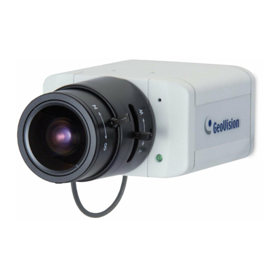
Page 14: Overview
1.2 Overview GV-BX110D Note: The Zoom Screw is only available for the varifocal lens model. - Page 15 Box Camera Name Description Audio Out Connects a speaker for audio output. Audio In Connects a microphone for audio input. Resets all configurations to factory default. Default See 10. Restoring to Default Settings later in the Quick Start Guide. Inserts a micro SD/SDHC card to store Memory Card Slot recording data.
- Page 16 GV-BX120D / 130D Series / 220D Series / 320D Series / 520D-0 Note: The Zoom Screw is only available for the varifocal lens models. The Iris Screw is only available for GV-BX520D-0. Name Description Connects to a portable monitor for setting Video Out the focus and angle of Box Camera during initial installation.
- Page 17 Box Camera Name Description Resets all configurations to factory default. Default See 10. Restoring to Default Settings later in the Quick Start Guide. Focus Screw Adjusts the focus of the camera. Iris Screw Adjusts the iris of the camera Microphone Records the sounds.
-
Page 18: Accessory Installation
Mount the supplied C-mount lens adapter / lens ring to the camera, and then attach the lens onto the camera body. GV-BX110D Install the supplied C-mount lens adapter to extend focal length for GV-BX110D as illustrated below. C-mount lens adapter... - Page 19 Box Camera GV-BX120D / 130D Series / 220D Series / 320D Series / 520D-0 The supplied lens rings for GV-BX120D / 130D Series / 220D Series / 320D Series / 520D-0 include 3 sizes in thickness: • 0.188 mm (transparent color) x 2 •...
-
Page 20: Infrared Illuminators (Gv-Ir Led / Gv-Ir Led T2)
1.3.2 Infrared Illuminators (GV-IR LED / GV-IR LED T2) Connect the infrared illuminator to the terminal block on the camera. See I/O Terminal Block, Box Camera chapter, GV-IPCam H.264 User’s Manual on the software CD, or GV-IR LED User’s Manual. Access the Web interface of the camera. - Page 21 Box Camera GV-IR LED T2 Click Apply. For Trigger by Input and Trigger IR by D/N functions, see the Video Settings section, Administrator Mode chapter in the GV-IPCam H.264 User’s Manual in the software CD.
-
Page 22: Connecting The Camera
1.4 Connecting the Camera The Box Camera is designed for indoor use. Please make sure the installing site is shielded from rain and moisture. GV-BX110D... - Page 23 Box Camera If you are using the varifocal lens model, plug the iris control cable to the Auto Iris Connector on the camera. Use a standard network cable to connect the camera to your network. Optionally connect a speaker and an external microphone. Optionally connect a monitor using a Video Out wire.
- Page 24 GV-BX120D / 130D Series / 220D Series / 320D Series / 520D-0 Plug the iris control cable to the Auto Iris Connector on the camera. Use a standard network cable to connect the camera to your network. Optionally connect a speaker and an external microphone. Optionally connect a monitor using a Video Out wire.
-
Page 25: Mini Fixed Dome
2. Mini Fixed Dome 2.1 Packing List • Mini Fixed Dome • Torx Wrench • 3-pin Terminal Block (not available for GV-MFD110) • DC 12V Power Adapter (not available for GV-MFD110) • Self Tapping Screw x 2 • Screw Anchor x 2 •... -
Page 26: Overview
2.2 Overview GV-MFD110 Name Description Resets the GV-MFD110 to factory default. Default Button See 10. Restoring to Default Settings later in the Quick Start Guide. Lens Rotates the les right/left to adjust focus. Focus Screw Loosens the screw to adjust the focus. Tilt Screw Loosens the screw to adjust the tilt angle. - Page 27 Mini Fixed Dome GV-MFD120 / 130 / 220 / 320 / 520 Name Description Resets the camera to factory default. See Default Button 14.3 Restoring to Factory Default Settings. Lens Receives image inputs. Tilt Screw Loosens the screw to adjust tilt angle. Built-In Microphone Provides one-way audio.
-
Page 28: Led Indicator
LED Indicator LED Name Description 1. Link Turns only when the network is connected. 2. ACT Turns on when data are being transmitted. 3. PWR Turns on when power is on. 4. SW RDY (Status) Turns on when the system is ready. -
Page 29: Installation
Mini Fixed Dome 2.3 Installation The Mini Fixed Dome is exclusively designed for ceiling mount. Please make sure the installing site is shielded from rain and moisture. Unscrew the housing cover using the torx wrench. Put the camera on the desired location and make 2 marks on the ceiling for screw anchors. - Page 30 Tilt Adjustment For GV-MFD110, adjust image clarity using the GV-IP Device Utility program. For details, see 7.3 Adjusting Image Clarity in the Quick Start Guide. Except for GV-MFD110, insert a Micro SD/SDHC card into the memory card slot. 10. Secure the camera’s cover using the torx wrench.
-
Page 31: Connecting The Camera
Mini Fixed Dome 2.4 Connecting the Camera Refer to the wire definition and illustrations below to connect the power and network. 2.4.1 Wire Definition For GV-MFD120 / 130 / 220 / 320 / 520, its data cable provides connections for power and network access. The wires are illustrated and defined below: Wire Color Definition DC 12V+... -
Page 32: Power And Network Connection
2.4.2 Power and Network Connection There are two ways to supply power to the camera: • Use a Power over Ethernet (PoE) adapter to connect the camera to the network, and the power will be provided at the same time. •... -
Page 33: Bullet Camera
3. Bullet Camera 3.1 Packing List • Bullet Camera • Lens (Megapixel and Built-In 16 IR LEDs) • Self Tapping Screw x 3 • Plastic Screw Anchor x 3 • Torx Wrench x 2 • Sun-Shield Cover Kit (1 Sun-Shield Cover, 2 Philips Head Screws, 2 Plastic Screw Spacers and 2 Hexagon Screws included) •... -
Page 34: Overview
3.2 Overview Name Description Memory Card Slot Receives a Micro SD/SDHC memory card. Zoom Screw Holds the zoom lens in place. Focus Screw Holds the focus lens in place Resets all configurations to factory default. Default Button See 10. Restoring to Default Settings later in the Quick Start Guide. -
Page 35: Installation
Bullet Camera 3.3 Installation The Bullet Camera is designed for outdoor use and can be mounted on ceiling and wall. Slide the cable clamp to the camera base. Install the Bullet Camera to the wall / ceiling. Remove the protection sticker from the camera’s cover. Connect the power, network and other cables to the camera. -
Page 36: Adjusting The Angles
Fasten the camera’s cover. Install the sun-shield cover to the Bullet Camera. For details, see 3.3.3 Installing the Sun-Shield Cover in the Quick Start Guide. 3.3.1 Adjusting the Angles The Bullet Camera is designed to be adjustable in three shafts. Tip: The three shafts are designed to offer easy and flexible ceiling / wall mount installation. - Page 37 Bullet Camera Adjust the angle of camera body to the right or the left, and fasten the panning lock screw. Second Shaft You can adjust the camera body up and down by 90, 112.5, 135, 157.5 or 180 degrees by using the gears inside the camera body and the camera base.
- Page 38 Adjust the angle of camera body to 90, 112.5, 135, 157.5 or 180 degrees. Then move the camera base to the left to combine the gears. Fasten the tilting lock screw. Third Shaft You can adjust the camera base by 360 degrees. Unscrew the base fixing screw with the torx wrench.
-
Page 39: Adjusting Lens And Inserting A Memory Card
Bullet Camera Adjust the angle of camera base, and fasten the base fixing screw. 0~360° 3.3.2 Adjusting Lens and Inserting a Memory Card To adjust the camera’s lens to produce a clear image and insert a memory card into the memory card slot. Loosen the camera’s cover. - Page 40 Loosen the fixing screw Slightly pull out the camera module. Loosen the Focus Screw and the Zoom Screw and adjust for image clarity using the GV-IP Device Utility program. For details, see 7.3 Adjusting Image Clarity in the Quick Start Guide. Insert a micro SD/SDHC card into the memory card slot.
-
Page 41: Inserting The Sun-Shield Cover
Bullet Camera 3.3.3 Inserting the Sun-Shield Cover After setting up the Bullet Camera, now you can install the sun-shield cover to the camera. Fasten the hexagon screws either on top or below the camera. Put the sun-shield cover on top of hexagon screws. Make sure to aim the rear hexagon screw at the edge of the sun-shield cover’s aperture for optimal sun-shield performance. -
Page 42: Connecting The Camera
3.4 Connecting the Camera Connect your Bullet Camera to power, network and the cables needed. 3.4.1 Wire Definition The cable of the Bullet Camera is illustrated and defined below: Wire Color Definition Digital In Brown DC 12V+ / AC 24V- Orange Digital Out Black... -
Page 43: Connecting The Power Cable
Bullet Camera 3.4.2 Connecting the Power Cable There are two ways to supply power to the Bullet Camera: • Use a Power over Ethernet (PoE) adapter to connect the camera to the network, and the power will be provided at the same time. •... -
Page 44: Applying Waterproof Treatment
3.4.3 Applying Waterproof Treatment To install the Bullet Camera outdoors, ensure to waterproof the cables. The camera’s body is waterproof, but the PoE, audio, power and I/O cables are not waterproof. Use waterproof silicon rubber or the like to apply waterproof treatment to the cables. -
Page 45: Vandal Proof Ip Dome
4. Vandal Proof IP Dome 4.1 Packing List • Vandal Proof IP Dome • Silica Gel Bag x 2 (one already placed inside the camera) • Screw Anchor x 4 • Torx Wrench x 1 • Ceiling Screw x 4 •... - Page 46 • Focus Adjustment Cap • DC 12V Power Adapter • 3-Pin Terminal Block • GV-IPCam H.264 Software • GV-IPCAM H.264 Quick • GV-NVR Software DVD Start Guide • GV-NVR Quick Start Guide Note: Focus Adjustment Cap is only needed and supplied for IK10+ models (GV-VD120D, 121D, 220D, 221D, 320D and 321D).
-
Page 47: Overview
Vandal Proof IP Dome 4.2 Overview Name Description Turns on (green) when the power is on and Power LED turns off when there is no power supply. Turns on (green) when the system Status LED operates normally and turns off when system error occurs. -
Page 48: Installation
4.3 Installation The Vandal Proof IP Dome is designed for outdoors. There are three ways to install the Vandal Proof IP Dome: hard-ceiling mount, in-ceiling mount and wall-pendent mount. 4.3.1 Hard-Ceiling Mount Unpack the camera package and take out the camera body. Unscrew the housing cover... - Page 49 Vandal Proof IP Dome Unscrew thread lock Unscrew the inner housing Take out the camera body...
- Page 50 Mark the position of four screw holes on the desired installation location, and drill holes in the marked locations. Drill the ellipse part if you wish to put the wires through it. Insert the screw anchors to the 4 holes on the ceiling. Secure the back cover to the ceiling with 4 ceiling screws.
- Page 51 Vandal Proof IP Dome Access and check the live image from the camera. See 7. Accessing the Camera in the Quick Start Guide. Adjust the camera to a desired angle as illustrated below. Tip: The 3-axis mechanism offers flexible and easy installation. Pan adjustment Tilt adjustment...
- Page 52 Rotational Adjustment 10. Hold the focus adjustment cap on top of the camera view and adjust for image clarity using the GV-IP Device Utility program. For details, see 7.3 Adjusting Image Clarity in the Quick Start Guide. 11. Screw on the thread lock as shown in step 1. 12.
-
Page 53: In-Ceiling Mount
Vandal Proof IP Dome 4.3.2 In-Ceiling Mount Follow step 1 in the Hard-Ceiling Mount section to remove the housing cover, thread lock and back cover, and take out the camera body. Cut out a circle with a diameter of 142 mm on the ceiling. Insert a blue screw to the indicated holes on the camera body. - Page 54 Screw in a plastic clip to the blue screw, hold it with one hand and use a screw driver to rotate the blue screw until the plastic clip moves half way down. Secure a T-cap on top of the blue screw with a small screw cap and a T-cap screw.
- Page 55 Vandal Proof IP Dome Insert the camera to the ceiling with the plastic screws moved inward. Move the blue screws out and rotate the blue screw with a screw driver until the plastic clip and the bottom of the camera body clamps the ceiling tightly.
-
Page 56: Wall-Pendent Mount
4.3.3 Wall-Pendent Mount For the wall-pendent mount installation, you need to purchase the wall mount bracket additionally. Take the wall mount bracket and make 2 marks on the wall for screw anchors. Drill the marks and insert 2 screw anchors. Insert the ceiling screws and leave enough distance (approximately 2 mm) to hang the wall mount bracket later. - Page 57 Vandal Proof IP Dome Hang the wall mount bracket on the ceiling screws and push the wall mount bracket downward. Tighten the screws to the wall. Follow step 1 in the Hard-Ceiling Mount section to remove the housing cover, thread lock and back cover, and take out the camera body. Secure the back cover to the wall mount bracket with four short screws and big screw caps (both are supplied with the wall mount bracket).
- Page 58 Follow step 1 in the Hard-Ceiling Mount section to secure the camera body with inner housing. Connect the network and power cables to the camera. See 4.4 Connecting the Camera in the Quick Start Guide. 10. Access and check the live image from the camera. See 7. Accessing the Camera in the Quick Start Guide.
-
Page 59: Connecting The Camera
Vandal Proof IP Dome 4.4 Connecting the Camera Connect your Vandal Proof IP Dome to power, network and other cables. 4.4.1 Wire Definition The cables for Vandal Proof IP Dome are illustrated and defined below. Wire Color Definition Black (thick) Shielding Ground Black (thin) DC 12V- / AC 24V+... -
Page 60: Connecting The Power Cable
4.4.2 Connecting the Power Cable There are two ways to supply power to the camera: • Use a Power over Ethernet (PoE) adapter to connect the camera to the network, and the power will be provided at the same time. •... -
Page 61: Fixed Ip Dome
5. Fixed IP Dome 5.1 Packing List • Fixed IP Dome • Torx Wrench x 1 • Mounting Plate x 1 • Short Screw Anchor x 3 • Ceiling Screw x 3 • Plate Screw x 3 • TV-out Wire DC 12V Power Adapter •... -
Page 62: Overview
5.2 Overview Name Description Focus Screw Adjusts the focus of the camera. Zoom Screw Adjusts the zoom of the camera. Rotational Screw Loosens to adjust the camera angle. Tilt Screw Loosens the screw to tilt the camera. Pan Disc Loosens to pan the camera. Connects to a portable monitor for setting Video Out the focus and angle of Fixed IP Dome... - Page 63 Fixed IP Dome Name Description Connects I/O devices. For details, see I/O Terminal Block Fixed IP Dome chapter in the GV-IPCam H.264 User’s Manual on the software CD. DC 12V Port Connects to power. Turns on (green) when the system Status LED operates normally and turns off when system error occurs.
-
Page 64: Installation
5.3 Installation The Fixed IP Camera is designed for indoors. There are two ways to install the Fixed IP Camera: hard-ceiling mount, wall-surface mount and wall-pendent mount. 5.3.1 Hard-Ceiling Mount Paste the supplied sticker onto a desired location on the ceiling. Drill the three red dots and the ellipse mark only if you wish to run the wires into the ceiling. - Page 65 Fixed IP Dome Take out the camera body Secure the camera body to the mounting plate with three ceiling screws. Connect the network and power cables to the camera. See 5.4 Connecting the Camera in the Quick Start Guide. Access and check the live image from the camera. See 7. Accessing the Camera in the Quick Start Guide.
- Page 66 Adjust the camera to a desired angle as illustrated below. Tip: The 3-axis mechanism offers flexible and easy ceiling / wall installation. Pan adjustment Tilt adjustment...
- Page 67 Fixed IP Dome Rotational Adjustment Adjust for image clarity using the GV-IP Device Utility program. For details, see 7.3 Adjusting Image Clarity in the Quick Start Guide. Focus Screw Zoom Screw Secure the housing cover as shown in step 2. Remove the indicated part when necessary.
-
Page 68: Wall-Surface Mount
5.3.2 Wall-Surface Mount Follow step 2 in the Hard-Ceiling Mount section to remove the housing cover and take out the camera body. Paste the supplied sticker onto a desired location on the wall. Drill the three red dots, and the ellipse mark only if you wish to run the wires into the wall. -
Page 69: Wall-Pendent Mount
Fixed IP Dome Follow steps 6 and 7 in the Hard-Ceiling Mount section to adjust the angle, focus and zoom of the camera. Follow step 8 in the Hard-Ceiling Mount section to secure the housing cover. 5.3.3 Wall-Pendent Mount For the wall-pendent mount installation, you need to purchase the wall mount bracket additionally. - Page 70 Hang the wall mount bracket on the wall mount screws and push the wall mount bracket downward. Tighten the wall mount screws to the wall. Follow step 2 in the Hard-Ceiling Mount section to remove the housing cover and take out the camera body. Secure the camera body to the wall mount bracket with three short screws (supplied with the wall mount bracket).
-
Page 71: Connecting The Camera
Fixed IP Dome 5.4 Connecting the Camera Use a standard network cable to connect the camera to your network. Optionally connect a speaker and an external microphone. Optionally connect a monitor using a Video Out wire. Enable the function by selecting the signal format in the TV Out field in the Web interface. -
Page 73: Cube Camera
6. Cube Camera 6.1 Packing List • Cube Camera • Supporting Rack • Screw x 3 • Screw Anchor x 3 • DC 12V Power Adapter • DC 5V Power Adapter (for GV-CB120 / 220) (for GV-CBW120 / 220) • GV-IPCAM H.264 Quick •... -
Page 74: Overview
6.2 Overview Name Description Microphone Receives sounds. Speaker Plays sounds. Connects to a 10/100 Ethernet. Turns red when the system powers on. Status LED Turns orange when the system is ready. Turns green when the camera is connected to the Internet. Turns blue when the wireless LAN LED service is enabled (for GV-CBW120 / 220 only). -
Page 75: Installation
Cube Camera 6.3 Installation Put the supporting rack on the desired location and make marks for screw anchors. Drill the marks and insert the screw anchors. Secure the supporting rack onto the wall using the supplied screws. Screw the camera onto the supporting rack and fasten the indicated screw. -
Page 76: Connecting The Camera
6.4 Connecting the Camera Use a standard network cable to connect the camera to your network. Connect power by plugging the supplied power adapter to the DC jack. The status LED of the camera will be orange. Then you can set the IP address for the unit. -
Page 77: Accessing The Camera
7. Accessing the Camera 7.1 System Requirement To access the Box Camera, Mini Fixed Dome, Bullet Camera, Vandal Proof IP Dome, Fixed IP Dome and Cube Camera through the Web browser, ensure your PC connects to the network properly and meets this system requirement: •... -
Page 78: Assigning An Ip Address
7.2 Assigning an IP Address Designed for use on the network, the Box Camera, Mini Fixed Dome, Bullet Camera, Vandal Proof IP Dome, Fixed IP Dome and Cube Camera must be assigned an IP address to make it accessible: Open your web browser, and type the default IP address http://192.168.0.10. - Page 79 Accessing the Camera To enable the updating of images in Microsoft Internet Explorer, you must set your browser to allow ActiveX Controls and perform a one-time installation of GeoVision’s ActiveX component onto your computer. IMPORTANT: Dynamic IP Address and PPPoE should only be enabled if you know which IP address the camera will get from the DHCP server or ISP.
-
Page 80: Adjusting Image Clarity
7.3 Adjusting Image Clarity You can adjust the image clarity using the GV-IP Device Utility. Make sure that you have connected your GV-IPCAM H.264 to the network and install the GV-IP Device Utility program under the same LAN. Note: This feature is only supported by Box Camera, GV-MFD110, Bullet Camera, Vandal Proof IP Dome, and Fixed IP Dome. - Page 81 Accessing the Camera Type the user name and password of the camera selected. The default is admin for both user name and password. This window appears. For GV-VD120D / 121D, VD-220D / 221D and VD-320D / 321D, hold the supplied Focus Adjustment Cap over the camera view. For details, see 7.3.1 Using Focus Adjustment Cap for details.
-
Page 82: Using Focus Adjustment Cap
7.3.1 Using Focus Adjustment Cap There are two types of Focus Adjustment Caps for GV-VD120D / 121D, GV-VD-220D / 221D and GV-VD-320D / 321D. Focus Adjustment Cap Type I: Hold the Focus Adjustment Cap on top of the camera view, keep it close to the lens and slightly tilt to one side to adjust the image. - Page 83 Accessing the Camera Do not leave a distance between the Focus Adjustment Cap and the camera.
-
Page 85: The Web Interface
8. The Web Interface... - Page 86 No. Name Function Play Plays live video. Stop Stops playing video. Talks to the surveillance area from the local Microphone computer. Speaker Listens to the audio around the camera. Snapshot Takes a snapshot of live video. File Save Records live video to the local computer. Switches to full screen view.
-
Page 87: Upgrading System Firmware
9. Upgrading System Firmware GeoVision periodically releases updated firmware on the website. The new firmware can be simply loaded into the GV-IPCAM H.264 by using the Web interface or IP Device Utility included in the software CD. IMPORTANT: While the firmware is being updated,... - Page 88 Click the Upgrade button to start the upgrade. WARNING: The interruption of power supply during updating causes not only update failures but also damages to the camera. In this case, please contact your sales representative and send your device back to GeoVision for repair.
-
Page 89: Restoring To Default Settings
10 Restoring to Default Settings GeoVision periodically releases updated firmware on the website. The new fir You can restore factory default settings through the Web interface or directly on the camera. 10.1 Using the Web Interface On the left menu of Web interface, select Management and select Tools. -
Page 90: Directly On The Camera
10.2 Directly on the Camera GV-BX110D Unplug the power cable and the network cable to start. Press and hold the default button on the back panel of the camera. Power on the camera using the power cable or PoE cable. The status LED on the front panel of the camera turns red. - Page 91 Restoring to Default Settings GV-BX120D / 130D Series / 220D Series / 320D Series / 520D-0 Unplug the power cable and the network cable to start. Press and hold the default button on the back panel of the camera. Power on the camera using the power cable or PoE cable. The status LED on the front panel of the camera turns on and then off twice.
- Page 92 GV-MFD110 Unplug the network cable to start. Unscrew the camera’s cover. Press and hold the default button. Power on the camera using the network cable. Wait until the network status LED turns off. This may take about 40 seconds. Soon after the network status LED turns off, release the default button. The process of loading default values is completed.
- Page 93 Restoring to Default Settings Bullet Camera Unplug the power cable and the network cable to start. Loosen the camera’s cover and remove the Silica Gel Bag. Unscrew the Fixing Screw and slightly pull out the camera module. Press and hold the Default button for 50 seconds while plugging the power cable.
- Page 94 Vandal Proof IP Dome Unplug the power cable and the network cable to start. Use a pin to press and hold the default button on the inner housing. Power on the camera using the power cable or PoE cable. When the status LED turns on and off twice, release the default button and the process of loading default is completed.
- Page 95 Restoring to Default Settings Fixed IP Dome Unplug the power cable and the network cable to start. Use a pin to press and hold the default button on the panel. Power on the camera using the power cable or PoE cable. When the status LED turns on and off twice, release the default button and the process of loading default is completed.
- Page 96 Power on the camera using the power cable. When the status LED turns on (orange) and off twice, release the default button and the process of loading default is completed. This may take about 35 seconds.
Need help?
Do you have a question about the GV-BX110D and is the answer not in the manual?
Questions and answers