Table of Contents
Advertisement
ENG
DIGITAL GSM
4000 Series Vandal Resistant Digital GSM Audio Intercom
with Proximity
4812 / VR4812
4812R / VR4812R
E n
1 8
/ 1
66251750-EN
V1.0 - 05/06/17
t e r
N u
O r
m b
S e
a r c
e r
1 /
1 6
h
0 8
: 3
5
Technical Manual
E n
t e r
N u
1 8
m b
/ 1
1 /
1 6
e r
0 8
: 3
5
We recommend
This equipment is installed by a
Competent Electrician, Security or
Communications Engineer.
Advertisement
Table of Contents

Related Manuals for Videx 4812


Summary of Contents for Videx 4812
- Page 1 DIGITAL GSM 4000 Series Vandal Resistant Digital GSM Audio Intercom with Proximity 4812 / VR4812 4812R / VR4812R t e r t e r a r c Technical Manual We recommend 66251750-EN This equipment is installed by a V1.0 - 05/06/17 Competent Electrician, Security or Communications Engineer.
-
Page 2: Declaration Of Conformity
CE conformity marking indicates that the product respects the requirements of the All Countries: UK Customers: applicable European Community Directives in force specifically EMC 2004/108/ VIDEX ELECTRONICS S.P.A. VIDEX SECURITY LTD. ECC, LVD 2006/95/ECC and CE-MARKING 93/68/ECC. CE marking is applied by the www.videx.it www.videxuk.com... -
Page 3: Table Of Contents
4000 Series Vandal Resistant Digital GSM Audio Intercom with Proximity Contents Introduction .......................................4 System Components and Available Versions ..........................6 Technical Information ..................................8 Additional Components ..................................9 Wiring Diagrams ..................................... 11 Auxiliary Input & Output ................................13 USB & RS485 Connection ................................15 General Directions for Installation .............................. -
Page 4: Introduction
SIM CARD SELECTION A SIM card is required for this product but not supplied by Videx. The digital GSM intercom can only accept a standard size SIM card (refer to the following SIM card size chart), both a micro-SIM and nano-SIM are not suitable. It is recommended to choose the SIM card which has the best coverage for the area in which the intercom panel will be installed. - Page 5 We would recommend using a GSM signal strength meter to survey the intended antenna location. Contact Videx for more information on where to purchase a tester.
-
Page 6: System Components And Available Versions
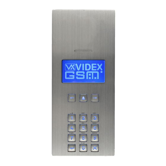
Two optional panels are available the Art.4812 (VR4812) and the Art.4812R (VR4812R) each with an integrated programmable keypad. The Art.4812 has 18 back lit buttons, 6 of which are alpha buttons (A - F), 10 are numeric buttons (0 - 9), plus an “ENTER”... - Page 7 4000 Series Vandal Resistant Digital GSM Audio Intercom with Proximity System Components and Available Versions ART. 4812 DIGITAL FRONT PANEL 103mm Speaker Proximity Reader Enter Number Enter Number Display Or Search 18/11/16 08:35 18/11/16 08:35 Keypad Art. 4812 / VR4812 Art.
-
Page 8: Technical Information
4000 Series Vandal Resistant Digital GSM Audio Intercom with Proximity Technical Information SPEAKER VOLUME ADJUSTMENT (DIP-SWITCH SETTINGS) There are 2 dip-switches located on the back of the digital GSM module next to the SIM card holder. They can be used to adjust the volume from the door intercom speaker (see table below). -
Page 9: Additional Components
4000 SERIES BACK BOXES AND MOUNTING FRAMES Both the Art.4812 and Art.4812R are designed to fit the 4000 series range of back boxes and frames, both surface and flush back boxes and mounting frames are available. The digital GSM requires a 2 module back box and frame. Front support frames are available in a gun metal grey finish, chrome finish (suffix \C to the frame code) or gold finish (suffix \G to the frame code). - Page 10 4000 Series Vandal Resistant Digital GSM Audio Intercom with Proximity Additional Components ART. 432 GSM ANTENNA The digital GSM also requires an antenna to function, the Art.432 GSM antenna connects to the SMA female bulkhead connection on the rear of the digital GSM module.
-
Page 11: Wiring Diagrams
Fig.7 below shows connections for a fail secure and a fail safe lock release and also volt free contacts. RS485 RS485 Fail Safe Fail Safe Volt Free Lock Release Lock Release Contacts Vandal Resistant 4000 Series Digital GSM Panel 4812 4812R RS485 Fig. 7 4000 Series Digital GSM - Technical Manual 66251750-EN - V1.0 - 05/06/17... - Page 12 4000 Series Digital GSM Audio Intercom with Proximity Wiring Diagrams TRADE INPUT AND PUSH TO EXIT INPUT CONNECTIONS Fig.8 below shows connections for the trade input using an Art.701T timeclock (in timeclock mode) and Fig.9 shows connections for the push to exit input using a push-to-make (normally open going closed) switch/button. RS485 Fig.
-
Page 13: Auxiliary Input & Output
4000 Series Digital GSM Audio Intercom with Proximity Auxiliary Input & Output AUXILIARY OUTPUT (AO) WHEN SET TO MODE 000 (ON DURING A CALL) Fig.10 below shows the connection for auxiliary output AO when the AOM mode is set to 000. The auxiliary output AO will activate once a call to an apartment has been made and will stay activated for the duration of the call. - Page 14 4000 Series Digital GSM Audio Intercom with Proximity Auxiliary Input & Output AUXILIARY OUTPUT (AO) WHEN SET TO MODE 002 (CALL ACTIVATED) Fig.12 below shows the connection for auxiliary output AO when the AOM mode is set to 002. The auxiliary output AO will activate once a call to an apartment has been made and will stay activated for the programmed auxiliary output time A1T.
-
Page 15: Usb & Rs485 Connection
The digital GSM can be connected using a standard micro-USB to USB cable as shown in Fig.14. This method of connection is primarily used for programming and setup of the digital GSM panel. Vandal Resistant 4000 Series Digital GSM Panel 4812 4812R RS485 USB cable Fig. - Page 16 GSM can only be connected as a ‘one-to-one’ bus connection to the PC, another GSM module cannot be connected on the same RS485 bus to the PC. Vandal Resistant 4000 Series Digital GSM Panel 4812 4812R switch to RS485 position...
-
Page 17: General Directions For Installation
4000 Series Vandal Resistant Digital GSM Audio Intercom with Proximity General Directions for Installation CABLE SIZE GUIDE Refer to the table below for the connections for the power supply output to the Art.4812/Art.4812R digital GSM intercom and the lock release connections. Distance... - Page 18 CONNECTION TO MAINS, SAFETY AND GUIDANCE NOTES IMPORTANT: PLEASE READ THESE INSTRUCTIONS CAREFULLY BEFORE COMMENCING WITH THE INSTALLATION. Videx recommends that any cabling and Videx product be installed by a competent and qualified electrician, security installation speclialist or communications engineer.
- Page 19 4000 Series Vandal Resistant Digital GSM Audio Intercom with Proximity General Directions for Installation Fig. 19 Fig. 20 Fig. 21 PANEL CARE The digital GSM panel facia is brushed stainless steel. It is important that the facia is cleaned on regular occasions to prevent dirt build up and tarnishing of the metal.
- Page 20 Fig.27. Fig. 27 4. After a further 10 seconds the GSM will emit a beep and below the Videx logo it will indicate the digital GSM is registering with the network, as shown in Fig.28.
-
Page 21: Reset Procedure
Fig.29. Fig. 29 5. After another delay the GSM will emit a beep and below the Videx logo it will indicate the digital GSM is registering with the network, as shown in Fig.30. 6. When the display shows that it is registering release the ‘0’ button, 7. -
Page 22: 4000 Series Back Box Installation
4000 Series Vandal Resistant Digital GSM Audio Intercom with Proximity 4000 Series Back Box Installation EXAMPLE: INSTALLING A 4000 SERIES TWO MODULE SURFACE BACK BOX (ART. 4882) Fig. 34 Fig. 35 Fig. 36 Fig. 37 Fig. 38 Fig. 39 Fig. 40 Fig. - Page 23 4000 Series Vandal Resistant Digital GSM Audio Intercom with Proximity 4000 Series Back Box Installation INSTALLING A SURFACE MOUNT DOOR STATION 1. Place the surface box against the wall (165-170cm between the top of the box and the floor level as shown in Fig.34) and mark the fixing holes A for the wall plugs B and the hole for the cables E (Fig.35).
- Page 24 4000 Series Vandal Resistant Digital GSM Audio Intercom with Proximity 4000 Series Back Box Installation EXAMPLE: INSTALLING A 4000 SERIES TWO MODULE FLUSH BACK BOX (ART. 4852) Fig. 46 Fig. 47 Fig. 48 Fig. 49 Fig. 50 Fig. 51 Fig. 52 Fig.
- Page 25 4000 Series Vandal Resistant Digital GSM Audio Intercom with Proximity 4000 Series Back Box Installation INSTALLING A FLUSH MOUNTING DOOR STATION 1. It is recommended that the flush box C is mounted into the wall approximately 165-170cm between the top of the box and the floor level as shown in Fig.46.
-
Page 26: Programming Via Alpha-Numeric Keypad
Example: When entering an apartment name, to type the name “VIDEX” the following buttons can be pressed on the keypad: Press button “8” , , 3 times = “V”; Press button “4” , , 3 times = “I”;... -
Page 27: Programming Flowcharts
4000 Series Vandal Resistant Digital GSM Audio Intercom with Proximity Programming Flowcharts ACCESSING MAIN PROGRAMMING MENU 4812 4812R Enter Number Enter Number DEFAULT WELCOME SCREEN Or Search 18/11/16 08:35 18/11/16 08:35 ENTER MASTER CODE First press ‘0’ . Enter the 4 digit master code ENTER A CODE (the default master code is ‘1111’), press the... - Page 28 4000 Series Vandal Resistant Digital GSM Audio Intercom with Proximity Programming Flowcharts 1. APARTMENT MENU PROG. MENU VER DG4.0.1 To exit from the main programming menu MAIN PROGRAMMING MENU press the CLEAR button to return to the default welcome screen. to exit APARTMENT MENU Press ‘1’...
- Page 29 4000 Series Vandal Resistant Digital GSM Audio Intercom with Proximity Programming Flowcharts 1. APARTMENT MENU (CONTINUED) 1.APT: 2.CODE: 3.DTO: 4.TB: 1. ADD/MODIFY APT 5.NAME: If no details require modifying to return back 2. DELETE APT 6.TEL 1: 7.TEL 2: to the apartment menu press the CLEAR 8.TEL 3: button 9.TEL 4:...
- Page 30 4000 Series Vandal Resistant Digital GSM Audio Intercom with Proximity Programming Flowcharts 2. PROXIMITY MENU PROG. MENU VER DG4.0.1 To exit from the main programming menu MAIN PROGRAMMING MENU press the CLEAR button to return to the default welcome screen. to exit PROXIMITY MENU Press ‘1’...
- Page 31 4000 Series Vandal Resistant Digital GSM Audio Intercom with Proximity Programming Flowcharts 3. GENERAL SETTINGS PROG. MENU VER DG4.0.1 To exit from the main programming menu MAIN PROGRAMMING MENU press the CLEAR button to return to the default welcome screen. to exit GENERAL SETTINGS MENU 1.
- Page 32 4000 Series Vandal Resistant Digital GSM Audio Intercom with Proximity Programming Flowcharts 3. GENERAL SETTINGS (CONTINUED) 1. AUX MODE:1 2. SPK VOL:10 3. MIC VOL:5 If no settings require adjusting then to return 4. SB VOL:85 GENERAL SETTINGS MENU to the main programming menu press the 5.
- Page 33 4000 Series Vandal Resistant Digital GSM Audio Intercom with Proximity Programming Flowcharts 4. CODE MENU PROG. MENU VER DG4.0.1 To exit from the main programming menu MAIN PROGRAMMING MENU press the CLEAR button to return to the default welcome screen. to exit CODE MENU On the main code menu it is possible to...
- Page 34 4000 Series Vandal Resistant Digital GSM Audio Intercom with Proximity Programming Flowcharts 5. TIME SETTINGS MENU PROG. MENU VER DG4.0.1 To exit from the main programming menu MAIN PROGRAMMING MENU press the CLEAR button to return to the default welcome screen. to exit TIME SETTINGS MENU On the time settings menu it is possible to setup...
- Page 35 4000 Series Vandal Resistant Digital GSM Audio Intercom with Proximity Programming Flowcharts 5. TIME SETTINGS MENU (CONTINUED) 1. CALL TIME:040 2. DIVERT TIME:015 If no time settings require adjusting then to 3. OPEN TIME:005 4. AUX TIME:005 TIME SETTINGS MENU return to the main programming menu press 5.
-
Page 36: Programming Screens
4000 Series Vandal Resistant Digital GSM Audio Intercom with Proximity Programming Screens MAIN PROGRAMMING MENU From the main programming menu (refer to Fig.57) it is possible to access the following sub menus: PROG. MENU VER DG4.0.1 1. Apartment menu 2. Proximity menu 3. - Page 37 4000 Series Vandal Resistant Digital GSM Audio Intercom with Proximity Programming Screens 1.1.2 DOOR/GATE ACCESS CODE The door/gate access code can be entered on the code screen (refer to Fig.62) and can be made up of a maximum of 6 digits (no letters). CODE: to confirm to cancel...
- Page 38 4000 Series Vandal Resistant Digital GSM Audio Intercom with Proximity Programming Screens TEL 2: TEL 3: TEL 4: to confirm to confirm to confirm to cancel to cancel to cancel Fig. 68 Fig. 69 Fig. 70 1.2 APARTMENT MENU (DELETE APT) Selecting option 2 from the apartment menu will access the memory location MEMORY LOCATION...
- Page 39 4000 Series Vandal Resistant Digital GSM Audio Intercom with Proximity Programming Screens 3 GENERAL SETTINGS MENU From the general settings menu (refer to Fig.78) it is possible to adjust the following 1. AUX MODE:1 panel settings: 2. SPK VOL:10 1. Auxiliary mode 3.
- Page 40 4000 Series Vandal Resistant Digital GSM Audio Intercom with Proximity Programming Screens 3.4 SPEECHBOARD VOLUME (SB VOL) Selecting option 4 from the general settings menu will access the speechboard volume control screen (refer to Fig.82). On this screen the speechboard volume of the SB VOL: (0-99) GSM panel can be adjusted.
- Page 41 4000 Series Vandal Resistant Digital GSM Audio Intercom with Proximity Programming Screens 3.7 PROXIMITY READER ENABLE/DISABLE (PROX ENABLE) Selecting option 7 from the general settings menu will access the proximity reader enable screen (refer to Fig.85). On this screen the proximity reader on the GSM panel PROX ENABLE: (0-1) can be switched ON and OFF.
- Page 42 4000 Series Vandal Resistant Digital GSM Audio Intercom with Proximity Programming Screens 4.2 ADMIN CODE Selecting option 2 from the code menu will access the admin code screen (refer to Fig.89). On this screen the admin code of the GSM panel can be changed. The current ADMIN CODE (4 DIGITS) setting will be highlighted on the second line of the screen (see Fig.89).
- Page 43 4000 Series Vandal Resistant Digital GSM Audio Intercom with Proximity Programming Screens 5.3 OPEN TIME Selecting option 3 from the time settings menu will access the open time screen (refer to Fig.94). On this screen the door/gate open time of the GSM panel can be adjusted. OPEN TIME: (1-255 Sec) The current setting will be highlighted on the second line of the screen (see Fig.94).
- Page 44 The LCD time of the GSM is the time delay of when the GSM display switches between the default welcome screen (see Fig.100 for Art.4812 and Fig.101 for Art.4812R on page 61) and a custom welcome screen or logo which has been uploaded to the panel using the GSMSK PC software.
-
Page 45: Programming Via Text Message
4000 Series Vandal Resistant Digital GSM Audio Intercom with Proximity Programming via Text Message PROGRAMMING THE DIGITAL GSM INTERCOM Programming the Digital GSM can also be carried out by sending text (SMS) messages. IMPORTANT NOTE: When you are required to use “ in a text message it is very important to use the correct symbol and not for example ‘... - Page 46 4000 Series Vandal Resistant Digital GSM Audio Intercom with Proximity Programming via Text Message Store balance check dial string 1111SDL”*#1345#” Check credit balance 1111BAL? 53 - 54 Store a master telephone no. 1111STM”07771234567” Latch the relay 1111RLA Unlatch the relay 1111RUL Latch auxiliary output AO 1111A1L...
- Page 47 4000 Series Vandal Resistant Digital GSM Audio Intercom with Proximity Programming via Text Message PROGRAMMING AND STORING USER INFORMATION IN A NEW MEMORY LOCATION (MEM) The memory location in the digital GSM is simply a position within the GSM’s internal memory where the user’s apartment information is stored.
- Page 48 Note that quotation marks “ and commas , are used where appropriate and the > character is used to insert a space between the words Videx and Tech for the username. The optional ? is included at the end so a confirmation text is sent back to the sender.
- Page 49 4000 Series Vandal Resistant Digital GSM Audio Intercom with Proximity Programming via Text Message ENABLE/DISABLE AN APARTMENTS DTO (DIAL TO OPEN) SETTING (STO) Each apartment can have their programmed telephone numbers set up as dial to open numbers. Once this feature is enabled for an apartment all the numbers stored for that apartment (primary and 3 divert numbers) will be set as dial to open numbers.
- Page 50 APT = 321 NAME = Mr Smith OK VIDEX GSM STORE OR CHANGE THE APARTMENT TELEPHONE NUMBERS (STN, STD, STE AND STF) Telephone numbers can be stored for the 500 available apartments. Each apartment can have up to four telephone numbers (if the first is busy or not answered in a certain time it can call a 2nd, 3rd and 4th number).
- Page 51 4000 Series Vandal Resistant Digital GSM Audio Intercom with Proximity Programming via Text Message SET CALL TIME (SPT) The call time is the maximum time in seconds that a call can last before the GSM panel automatically clears the call down. The time can be from 1 second up to 255 seconds and begins from when the call is made from the panel.
- Page 52 For UK customers other useful numbers which can be used with this feature are as follows. For other countires please check the service provider’s web sites for other useful codes. IMPORTANT NOTE: Although the following codes have been confirmed to work with the GSM intercom Videx offers no guarantee that other codes from other network providers will work.
- Page 53 IMPORTANT NOTE: Videx are only aware of the balance check dial string codes for the network providers mentioned above. Check dial string codes for other networks are currently unavailable at this time. Please also note that this programming function is only applicable for pay as you go SIM cards.
- Page 54 4000 Series Vandal Resistant Digital GSM Audio Intercom with Proximity Programming via Text Message In addition to this feature the digital GSM also has the facility to monitor the available credit and then text the user to inform them when the credit has fallen below £5.00, €5.00 or $5.00. It will then remind the user with another text after every 5 calls until the credit has either increased or if it runs out.
- Page 55 TB 1 06002330 OK VIDEX GSM Any apartment which is then assigned to timeband 1 will only receive calls between the hours of 06:00 in the morning until 23:30 at night, calls after 23:30, i.e. 23:31 onwards will stop.
- Page 56 The digital GSM intercom will reply with the following text: CLK = 17/04/24, 10.05 OK VIDEX GSM SILENT DIALLING MODE (AUE) When the digital GSM is calling the telephone number stored there is a choice of either hearing the ringing noise from the intercom panel or just hearing beeps to indicate a call is in progress.
- Page 57 The digital GSM can store up to 2000 fobs/cards (0000 - 1999). The reader can be programmed with any one of the following fobs: • 955/T or 955/C = Videx fobs or cards. These fobs and cards have no site code and have a 5 digit user code, so the PBY function must be set to 002 (the default setting, checking for 2 bytes).
- Page 58 The digital GSM intercom will reply with the following text: STORED IN nnnn OK VIDEX GSM where nnnn = the memory location between 0000 - 0499 of where the number is stored.
- Page 59 The digital GSM intercom will reply with the following text: STORED IN nnnn OK VIDEX GSM where nnnn = the memory location between 0000 - 0499 of where the number is stored.
- Page 60 For the application of these commands please contact Videx Technical on tel: 0191 224 3174. For overseas customers please contact Videx customer support on tel: (+39) 0734 631 699.
-
Page 61: System Operation
4000 Series Vandal Resistant Digital GSM Audio Intercom with Proximity System Operation STANDBY MODE When the digital GSM intercom is in standby the display will show the standard welcome message, refer to Fig.100 (Art.4812) and Enter Number Enter Number Fig.101 (Art.4812R). The date and time is Or Search... - Page 62 4000 Series Vandal Resistant Digital GSM Audio Intercom with Proximity System Operation ENTERING A DOOR/GATE AND TRADE ACCESS CODE If an access code is programmed into the GSM intercom first press the ‘0’ button, ENTER A CODE ENTER A CODE the ‘ENTER A CODE’...
-
Page 63: User Commands
4000 Series Vandal Resistant Digital GSM Audio Intercom with Proximity User Commands USER COMMAND TABLES The first user table shows the user commands that can be carried out during a call. Successful commands are signalled by two beeps from the telephone, errors are signalled by four beeps. IMPORTANT NOTE: When the ED# function has been enabled the user must press the # button on their phone before pressing any of the following user commands (also refer to page 56 for further information). -
Page 64: Additional User Information
The example below shows the reply to expect from the digital GSM: SIGNAL = 31 BER = 0 OK VIDEX GSM DIALLING INTO THE DIGITAL GSM FROM ANOTHER TELEPHONE There are three possible outcomes to dialling into the digital GSM intercom depending on the telephone number you are dialling in from and the features setup during programming. - Page 65 4000 Series Vandal Resistant Digital GSM Audio Intercom with Proximity Additional User Information Two short beeps followed Call made to a stored apartment number but no Program a telephone number for the apartment. by a long beep. actual telephone number stored. During this time the GSM display will indicate that it is attempting to call an...
-
Page 66: User Management
4000 Series Vandal Resistant Digital GSM Audio Intercom with Proximity User Management RECORD SHEET In order to manage the digital GSM intercom effectively it is recommended that an up to date record sheet is kept for all the programming particularly if there is a high volume of telephone numbers and fob/cards stored in the GSM intercom. This will also be useful if any future changes need to be made. -
Page 67: Troubleshooting
4000 Series Vandal Resistant Digital GSM Audio Intercom with Proximity Troubleshooting SYSTEM CHECKS AND TESTING The following table can be used to help diagnose any potential issues that may occur during installation and the system checks that can be carried out to help resolve them. SYMPTOM TEST Interference on the speech. - Page 68 3. After the GSM intercom has rebooted test the door opening feature from the telephone during a call. If none of the solutions above resolve the problem then please contact Videx technical on tel: 0191 224 3174 for further assistance. For overseas customers contact Videx customer support on tel: (+39) 0734 631 699 for further assistance.
-
Page 69: General Information
DATE SOFTWARE VERSION REVISION 02/01/17 DG4.0.0 Launch of the digital GSM (4812, 4812R). 15/05/17 DG4.0.1 Update AT command to include DTMF adjustment feature. FURTHER READING Additional programming information using the GSMSK PC software can be found in the following technical manual: •... -
Page 70: Notes
4000 Series Vandal Resistant Digital GSM Audio Intercom with Proximity Notes 4000 Series Vandal Resistant Digital GSM - Technical Manual 66251750-EN - V1.0 - 05/06/17... - Page 71 4000 Series Vandal Resistant Digital GSM Audio Intercom with Proximity Notes 4000 Series Vandal Resistant Digital GSM - Technical Manual 66251750-EN - V1.0 - 05/06/17...
- Page 72 THE POWER TO SECURE MANUFACTURER CUSTOMER SUPPORT VIDEX ELECTRONICS S.P.A. All Countries: Via del Lavoro, 1 - 63846 Monte Giberto (FM) Italy VIDEX ELECTRONICS S.P.A. Tel (+39) 0734 631669 - Fax (+39) 0734 632475 www.videx.it - technical@videx.it www.videx.it - info@videx.it...
Need help?
Do you have a question about the 4812 and is the answer not in the manual?
Questions and answers