
Related Manuals for Emerson FXMP25


Summary of Contents for Emerson FXMP25
-
Page 1: User Guide
User Guide FXMP25 Field Controller Part Number: 0476-0009-03 Issue: 3 www.controltechniques.com... - Page 2 General Information The manufacturer accepts no liability for any consequences resulting from inappropriate, negligent or incorrect installation or adjustment of the optional operating parameters of the equipment or from mismatching the field controller with the motor. The contents of this guide are believed to be correct at the time of printing. In the interests of a commitment to a policy of continuous development and improvement, the manufacturer reserves the right to change the specification of the product or its performance, or the contents of the guide, without notice.
-
Page 3: Table Of Contents
Motor .......................7 Adjusting parameters ................7 1.10 Electrical installation ................8 Product information ............9 Ratings ....................9 Nameplate description ................9 FXMP25 features and options ...............10 Mechanical installation .............11 Fire protection ..................11 Electrical terminals ................14 Routine maintenance ................14 Electrical installation ............15 Electrical connections ................16 Protective ground connections ..............17... - Page 4 Setting-up ................44 Technical data ..............53 Ratings ....................53 FXMP25 derating for extended ambient operation ........53 Power dissipation ..................53 AC supply requirements ................54 Line reactors ..................54 Temperature and humidity ..............55 Storage ....................55 Altitude ....................55 IP rating ....................55 8.10 Corrosive gasses ...................56 8.11 RoHS compliance ..................56...
-
Page 5: Declaration Of Conformity
Declaration of Conformity Control Techniques Ltd, The Gro, Newtown, Powys UK. SY16 3BE FXMP25 Field Controller The field controller product listed above has been designed and manufactured in accordance with the following European harmonized standards: Adjustable speed electrical power drive systems - safety... -
Page 6: Safety Information
- for example, an over- speed protection device in case of failure of the field control. FXMP25 User Guide www.controltechniques.com Issue Number: 3... -
Page 7: Environmental Limits
(EMC) regulations. Particular attention must be given to the cross-sectional areas of conductors, the selection of fuses and other protection, and protective ground connections. The FXMP25 User Guide contains instructions for achieving compliance with specific EMC standards. Within the European Union, all machinery in which this product is used must comply... -
Page 8: Electrical Installation
The field controller contains capacitors that remain charged to a potentially lethal voltage after the AC supply has been disconnected. If the field controller has been energized, the AC supply must be isolated at least five minutes before work may continue. FXMP25 User Guide www.controltechniques.com Issue Number: 3... -
Page 9: Product Information
The value is stated for worst-case conditions. Continuous AC Continuous DC input current output current Nameplate description Figure 2-1 Typical FXMP25 rating label External Field Mentor Platform Customer and Maximum field current (A) date code Line input voltage/... -
Page 10: Fxmp25 Features And Options
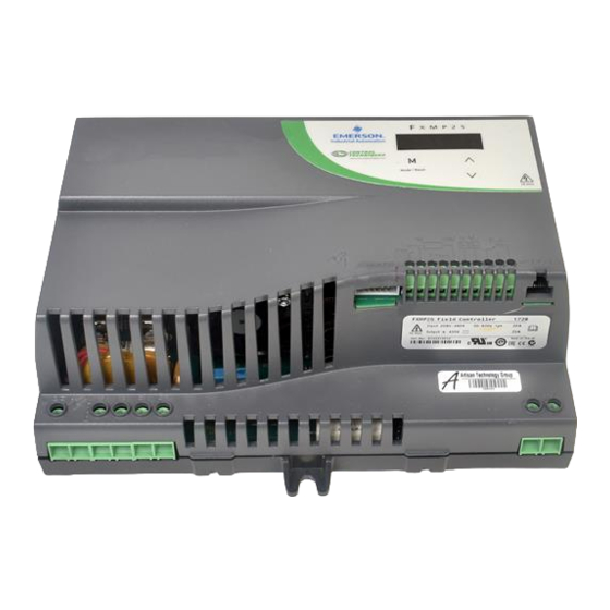
FXMP25 features and options Figure 2-2 FXMP25 features FXMP25 Display Mode /Reset STORED CHARGE 10 min Mentor MP/ serial port connector AC supply Ground Armature voltage Mentor II Control and field output connection feedback connector terminals connections connections 2.3.1 Options available for FXMP25... -
Page 11: Mechanical Installation
Enclosure can be metal and/or polymeric, polymer must meet requirements which can be summarized for larger enclosures as using materials meeting at least UL 94 class 5VB at the point of minimum thickness. Air filter assemblies to be at least class V-2. FXMP25 User Guide Issue Number: 3 www.controltechniques.com... - Page 12 ) B o t t o m o f f i r e Bottom of fire enclosure e n c l o s u r e FXMP25 User Guide www.controltechniques.com Issue Number: 3...
- Page 13 168.5mm 162mm 176mm (7.57in) (6.63in) (6.38in) (6.93in) 123.5mm (4.86in) 90.27 (3.55in) Table 3-1 Back-plate information Recommended Torque range screw size 1.5 N m (1.1 Ib ft) to 2.5 N m (1.8 Ib ft) FXMP25 User Guide Issue Number: 3 www.controltechniques.com...
-
Page 14: Electrical Terminals
Ground connection Power connections Routine maintenance The FXMP25 should be installed in a cool, clean, well ventilated location. Contact with moisture and dust should be prevented. Regular checks of the following should be carried out to ensure the installation reliability... -
Page 15: Electrical Installation
The Stop function of the Drive does not remove dangerous voltages from the FXMP25 controller or the driven machine. WARNING AC supplies to the FXMP25 controller must be disconnected at least 5 minutes before any cover is removed or servicing work is performed. Isolation device... -
Page 16: Electrical Connections
Electrical connections When operating in stand alone mode, a relay should be provided to indicate to the controller that the unit has tripped and to protect against an overspeed condition. Figure 4-1 FXMP25 power connections FXMP25 Mode /Reset STORED CHARGE... -
Page 17: Protective Ground Connections
FXMP25. Line reactors The FXMP25, in common with all naturally commutated SCR drives, causes voltage notches at the input supply terminals. To avoid disturbances with other equipment using the same supply, the addition of external line inductance is strongly recommended in order to restrict the depth of notches imposed. -
Page 18: Cable And Fuse Size Ratings
The selection of the correct fuse is essential to ensure the safety of the installation. WARNING The AC supply inputs in the FXMP25 controller are fitted with auxiliary fuses for protection against short circuits in the FXMP25 controller and field-winding of the motor. - Page 19 FXMP25 is tripping field loss (FdL) while enabled. Electric shock risk If the FXMP25 controller has been energized, the supply must be isolated for at least five minutes. This allows the internal capacitors to discharge fully before work may WARNING commence.
- Page 20 Figure 4-2 Removing the internal semiconductor fuses 1. Remove mounting screws (M6 recommended). 2. Apply pressure at the two points shown on the bottom of the FXMP25 to release the terminal cover clips. 3. Open the terminal cover in the direction shown.
- Page 21 The recommended filter has been selected to be compatible with the SCR control circuit in the FXMP25 unit. It is strongly recommended that no other filter type be used. SCRs can be damaged by filters with unsuitable output impedance (capacitors CAUTION connected directly to the output).
- Page 22 Figure 4-3 and Figure 4-4. Figure 4-3 Surge suppression for digital and unipolar inputs and outputs Signal from plant Signal to drive 30V zener diode e.g. 2xBZW50-15 FXMP25 User Guide www.controltechniques.com Issue Number: 3...
- Page 23 Analog input Function Current demand input Full scale voltage range 0 to 10 V Absolute maximum voltage range -18 V to 30 V Input resistance 44 kΩ Resolution 10 bits Sample period 4 ms FXMP25 User Guide Issue Number: 3 www.controltechniques.com...
- Page 24 Resolution 10 bits Update period 4 ms Fail relay common Fail relay normally open Fail relay normally closed FXMP25 OK indicator (See Pr 01 and Function Pr 27. Type Form C 250/125 Vac category 1/2 Rating 5 A nominal resistive load...
- Page 25 The communications port applies a 2 unit load to the communications network. 4.8.2 Serial communications connections The FXMP25 has a serial communications port (serial port) as standard supporting two wire EIA(RS)-485 communications. See Table 4-8 for the connection details for the RJ45 connector.
- Page 26 When using one of the above converters or any other suitable converter with the FXMP25, it is recommended that no terminating resistors be connected on the network. It may be necessary to 'link out' the terminating resistor within the converter depending on which type is used.
-
Page 27: Getting Started
The left hand display flashing indicates that the up and down keys will select a different parameter to be viewed. Holding the up key will cause the parameter number to increment to Pr 99. FXMP25 User Guide Issue Number: 3 www.controltechniques.com... -
Page 28: Resetting The Field Controller
FXMP25 User Guide www.controltechniques.com Issue Number: 3... -
Page 29: Setting The Controller Back To Default Values
Parameters are automatically saved when the MODE key is pressed when going from parameter edit mode to parameter view mode. A parameter change is not saved if a drive trip occurs when the parameter is changed. NOTE FXMP25 User Guide Issue Number: 3 www.controltechniques.com... -
Page 30: Parameters
Field flux output scaling factor Field current feedback scaling Field voltage mode select Autotune AC supply FXMP25 OK flux level Enable field control FXMP25 OK hysteresis level Field mode Flux threshold level exceeded Economy level selected Motor saturation breakpoint 1... -
Page 31: Full Parameter Descriptions
Update rate Actioned on exit of edit mode or FXMP25 reset If this parameter is set to a non-zero value and edit mode is exited or the FXMP25 is reset when the FXMP25 is inactive, the selected default parameters will automatically be loaded. - Page 32 Update rate Background The maximum value of Pr 02 is 860 which without any scaling will be converted to 10 V. This parameter should be adjusted by the user for other full scale voltages. FXMP25 User Guide www.controltechniques.com Issue Number: 3...
- Page 33 At the end of the autotune routine, Pr 77 is set to 0 (off) when Pr 81 = 0. If Pr 81 = 1, then the controller remains in the enabled condition as controlled by the digital input. FXMP25 OK flux level Coding Range 0.0 to 100.0 %...
- Page 34 FXMP25 OK hysteresis level Coding Range 0.0 to 25.0 % Default 0.0 % Update rate 16 ms Set the hysteresis from the level set in Pr 25 to eliminate relay bounce when the level is reached. If the value is greater or equal to the threshold Pr 25 plus half the hysteresis band Pr 26 the output becomes active, or if the value is less than the threshold minus half the hysteresis the output becomes inactive.
- Page 35 Set Pr 29 Motor saturation breakpoint 1 = 50 x set speed / actual speed (Speed 50) • Set Pr 30 Motor saturation breakpoint 2 = 75 x set speed / actual speed (speed 75). • Press mode to save parameters. FXMP25 User Guide Issue Number: 3 www.controltechniques.com...
- Page 36 Indicates percentage voltage demand. Negative value in full control indicates energy absorption to force field down quicker. Field firing angle Coding ° Range 0.0 to 180.0 Update rate Background write 0 ° = fully phased forward full volts applied to the field. FXMP25 User Guide www.controltechniques.com Issue Number: 3...
- Page 37 When this parameter is set to OFF (0) the field controller operates with the field weakening voltage loop. When set to On (1) the flux level is determined by reference on terminal 3. FXMP25 User Guide Issue Number: 3 www.controltechniques.com...
- Page 38 0.00 to 25.00A Default Eur: 5.00, USA: 25.00 Update rate Background read This parameter will be set to the field current of the motor and will define the 100 % point for the field controller. FXMP25 User Guide www.controltechniques.com Issue Number: 3...
- Page 39 EMF of the machine to be higher than expected. The parameter can be adjusted by monitoring the armature voltage while running at full speed. See Pr 30 on page 30 for further information. FXMP25 User Guide Issue Number: 3 www.controltechniques.com...
- Page 40 A reset can be achieved by holding the mode key for 2 seconds. Once an operating mode has been setup the controller must be power cycled to NOTE change modes. FXMP25 User Guide www.controltechniques.com Issue Number: 3...
- Page 41 If Pr 81 = 0 (Eco), the digital input controls parameter Pr 80. This is inverted so Pr 80 is 'ON' by default. If Pr 81 = 1 (F.Ctl), the digital input controls the parameter Pr 77. Reset the drive for the change to take place. FXMP25 User Guide Issue Number: 3 www.controltechniques.com...
- Page 42 Baud rate Coding Range 0 to 4 Default Update rate Background read Used to define the baud rate of the serial interface. Parameter value String/baud rate 2400 4800 9600 19200 38400 FXMP25 User Guide www.controltechniques.com Issue Number: 3...
- Page 43 1.00 to 99.99 Update rate Write at power-up The power PCB software version consists of two numbers xx.yy. Where xx specifies a change that affects hardware compatibility, yy specifies a change that affects product documentation. FXMP25 User Guide Issue Number: 3 www.controltechniques.com...
-
Page 44: Setting-Up
The field current must not be allowed to become zero while the motor is running. WARNING During the following procedure, you will be required to apply AC power to the FXMP25 controller and to run the motor. Before applying AC power, ensure the following: The controller is correctly connected. - Page 45 To enable the field controller: controller • Set Pr 77 (Enable field control) = On (1) Close field Close field economy input (Ion) so that Pr 80 (Economy level economy jumper select) is OFF (0). FXMP25 User Guide Issue Number: 3 www.controltechniques.com...
-
Page 46: Fxmp25 User Guide
Field weakeneing Maximum I gain voltage set-point flux Minimum flux Armature voltage Armature voltage Armature voltage Field flux feedback output scaling output scaling Armature voltage output Va Field flux output If FXMP25 User Guide www.controltechniques.com Issue Number: 3... - Page 47 Field mode Percentage I gain voltage demand Flux feedback Flux calculator Motor saturation breakpoint 1 Motor saturation breakpoint 2 Rated field current Rated field compensation factor Drive healthy / OK Field current feedback FXMP25 User Guide Issue Number: 3 www.controltechniques.com...
- Page 48 • Motor field is connected. • The MP port on the FXMP25 is connected to the external Before power up field controller port on the Mentor MP using a shielded straight through RJ45 to RJ45 lead, maximum length 100 m.
- Page 49 The bridge change only occurs when the flux is zero. All parameters except Pr 07 and Pr 78 are set-up by the Mentor MP and therefore NOTE cannot be adjusted on the FXMP25 field controller. FXMP25 User Guide Issue Number: 3...
- Page 50 If the field controller trips, see Chapter 9 Diagnostics page 60. Setting up the field • Set parameter Pr 11 on FXMP25 to be the same value as current feedback Pr 6.11 on Mentor II. scaling To select Mentor II mode •...
- Page 51 User Guide for an example calculation). FXMP relay and Mentor II logic functions should be used to set Pr 6.13 to 0 to disable firing pulses during fault conditions in the disabled state. FXMP25 User Guide Issue Number: 3 www.controltechniques.com...
- Page 52 Pr 9.07 = 806 Pr 9.09 = 8.11 – drive disabled. Pr 8.17 = 1034 – force an ‘Et’ trip if FXMP25 relay opens and firing angle reaches end- stop and drive is disabled. Connect digital outputs 1 and 2 and digital input 7 together.
-
Page 53: Technical Data
Continuous AC Continuous DC input current output current FXMP25 derating for extended ambient operation Figure 8-1 FXMP25 derating for extended ambient operation 21.5 Ambient temperature( C) ° Power dissipation Table 8-1 shows the maximum field controller losses, assuming 480 V supply on a 300 V field. -
Page 54: Ac Supply Requirements
The FXMP25 is rated for a nominal supply up to 480 Vrms. 8.4.1 Supply types The FXMP25 is suitable for use with any supply type, i.e. TN-S, TN-C-S, TT, IT, with grounding at any potential, i.e. neutral, centre or corner (grounded-delta). 8.4.2... -
Page 55: Temperature And Humidity
Low voltage capacitors cannot be reformed due to their location in the circuit and thus may require replacing if the FXMP25 is stored for a period of 2 years or greater without power being applied. -
Page 56: Corrosive Gasses
8.11 RoHS compliance FXMP25 meets EU directive 2002-95-EC for RoHS compliance. 8.12 Vibration Maximum recommended continuous vibration level 0.14 g rms broad-band 5 to 200 Hz. -
Page 57: Acoustic Noise
Refer to Figure 3-3 Overall dimensions on page 13. 8.15 Weight The overall weight of the FXMP25 is 1.70 kg (3.70 Ib). 8.16 Cable and fuse size ratings Refer to section 4.5 Cable and fuse size ratings on page 18. -
Page 58: Electromagnetic Compatibility (Emc)
8.17 Electromagnetic compatibility (EMC) This is a summary of the EMC performance of the FXMP25. For full details, refer to the FXMP25 EMC data sheet which can be obtained from the supplier of the FXMP25. Table 8-5 Immunity compliance Type of... - Page 59 Emission The following standards are met for cable lengths up to 100m. Table 8-6 FXMP25 emission compliance Filter Conformity No filter Schaffner FN3280H-25-33 Filters can be sourced directly from Schaffner. Key (shown in decreasing order of permitted emission level): EN 61800-3:2004 second environment, restricted distribution (Additional measures may be required to prevent interference).
-
Page 60: Diagnostics
Techniques distributor for repair. Trip indications If the unit trips, the field output is disabled and the FXMP25 ceases to control the field. The left hand display indicates that a trip has occurred, and the right hand display shows the trip. - Page 61 Diagnosis Internal EEPROM trip Internal FXMP25 EEPROM checksum. When this trip occurs all the parameters are set to default. The trip can only be removed by entering a load default command (i.e. Eur or USA) into Pr 00 before re-setting the FXMP25.
- Page 62 Trip categories Trips can be grouped into the following categories. It should be noted that a trip can only occur when the FXMP25 is not tripped or is already tripped but with a trip with a lower priority number. Table 9-2 Trip categories...
- Page 63 Trip 3 Behavior of the FXMP25 when tripped If the FXMP25 trips the output of the FXMP25 is disabled so that the FXMP25 stops controlling the field. If any trip occurs the following read only parameters are frozen to help in diagnosing the cause of the trip.
-
Page 64: Ul Listing Information
480 Vac when installed as per point 7 above in section 10.1. 10.3 Maximum continuous current The device is listed as having the maximum continuous current ratings as specified in section 2.1 Ratings on page 9. FXMP25 User Guide www.controltechniques.com Issue Number: 3... - Page 66 0476-0009-03...
Need help?
Do you have a question about the FXMP25 and is the answer not in the manual?
Questions and answers