Emerson FISHER 627 Series Instruction Manual
Pressure reducing regulators
Hide thumbs
Also See for FISHER 627 Series:
- Instruction manual (20 pages) ,
- Instruction manual (24 pages)
Table of Contents
Advertisement
Quick Links
Instruction Manual
Form 5252
March 2008
627 Series Pressure Reducing Regulators
W4793
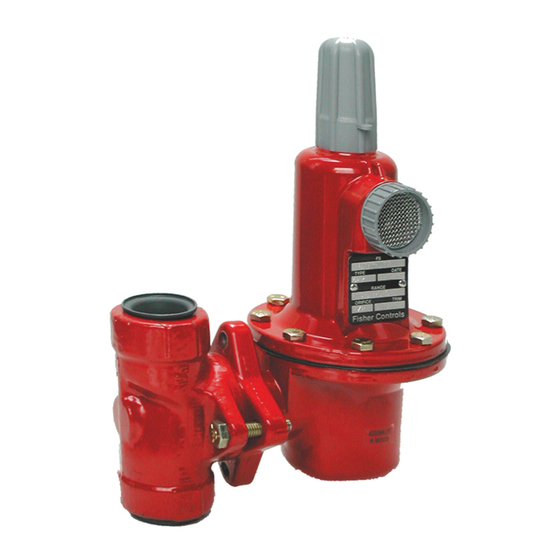
Figure 1. Typical 627 Series Self-Operated
Pressure Reducing Regulator
Introduction
Scope of Manual
This manual provides instructions for the Installation,
Adjustment, Maintenance, and Parts Ordering for
the 627 Series regulators. These regulators usually
are shipped separate for line installation, although
sometimes they are shipped installed on other
equipment. Refer to the Instruction Manual for the other
equipment for installation and operating instructions.
Description
The 627 Series self-operated pressure reducing
regulators (Figure 1) are for high and low pressure
systems. These regulators can be used with natural
gas, air, or a variety of other gases. Performance
characteristics vary according to construction.
Specifications
The Specifications section gives some general
specifications for the 627 Series regulators. The
nameplates (Figure 2) give detailed information for a
particular regulator as it comes from the factory.
www.emersonprocess.com/regulators
NUMBER 1
NUMBER 2
10B3679-D
Figure 2. Nameplates
627 Series
Advertisement
Table of Contents

Related Manuals for Emerson FISHER 627 Series


Summary of Contents for Emerson FISHER 627 Series
- Page 1 627 Series Instruction Manual Form 5252 March 2008 627 Series Pressure Reducing Regulators NUMBER 1 NUMBER 2 10B3679-D Figure 2. Nameplates W4793 Figure 1. Typical 627 Series Self-Operated Description Pressure Reducing Regulator The 627 Series self-operated pressure reducing regulators (Figure 1) are for high and low pressure Introduction systems.
-
Page 2: Specifications
627 Series Specifications Available Constructions Maximum Spring and Diaphragm Casing Pressure See Table 2 Type 627: Self-operated pressure reducing regulator equipped with a pitot tube for greater Maximum Body Outlet Pressure (Types 627M, regulated capacities (Figure 7). 627MR, and 627HM Only) Type 627R: Type 627 with internal relief and with 2000 psig (138 bar) for NPT steel, 1480 psig an open throat (Figure 8). - Page 3 627 Series Table 1. Maximum Inlet Pressures, Differential Pressures, and Outlet Pressure Ranges OUTLET PRESSURE ORIFICE SIZE, MAxIMUM INLET MAxIMUM DIFFERENTIAL TYPES RANGE, SPRING PART INCHES (mm) PRESSURE, PSIG (bar) PRESSURE, PSID (bar d) NUMBER, AND COLOR 3/32 (2,38) 2000 (138) 2000 (138) to 20 psig 1/8 (3,18)
-
Page 4: Installation
627 Series Table 2. Maximum Spring and Diaphragm Casing Pressure SPRING AND TYPES 627H TYPE 627, TYPE 627R, TYPE 627M, TYPE 627MR, MAxIMUM PRESSURE DESCRIPTION DIAPHRAGM AND 627HM, PSIG (bar) PSIG (bar) PSIG (bar) PSIG (bar) CASING STYLE PSIG (bar) Die cast aluminum Not Available Maximum pressure to spring and diaphragm... - Page 5 627 Series VENT VALVE GRAVITY FEED ALCOHOL DRIP POT TYPE 627M SET LOWER THAN WORkING REGULATOR CONTROL LINE NEEDLE VALVE INLET WORkING REGULATOR A3725 Figure 3. Schematic of De-Icer System Remote Vent Line Installation WARNING All 627 Series regulators have a vent assembly A regulator may vent some gas to the installed in the 3/4-inch threaded NPT spring case vent atmosphere.
- Page 6 627 Series Table 3. Type 627R Internal Relief Performance OUTLET MAxIMUM MAxIMUM INLET PRESSURE TO kEEP MAxIMUM ALLOWABLE DOWNSTREAM OUTLET PRESSURE ALLOWABLE SYSTEM PRESSURE FROM BEING ExCEEDED, PSIG (bar) PRESSURE RANGE, SPRING DOWNSTREAM Orifice Size, Inches (mm) SETTING, PART NUMBER, SYSTEM PRESSURE, PSIG (bar) 3/32 (2,38)
- Page 7 627 Series Table 3. Type 627R Internal Relief Performance (continued) MAxIMUM INLET PRESSURE TO kEEP MAxIMUM ALLOWABLE DOWNSTREAM OUTLET MAxIMUM ALLOWABLE OUTLET PRESSURE SYSTEM PRESSURE FROM BEING ExCEEDED, PSIG (bar) PRESSURE DOWNSTREAM RANGE, SPRING PART SETTING, SYSTEM PRESSURE, Orifice Size, Inches (mm) NUMBER, AND COLOR PSIG (bar) PSIG (bar)
-
Page 8: Maintenance
627 Series Table 4. Maximum Torque Values kEY NUMBER DESCRIPTION MAxIMUM TORqUE, FOOT-POUNDS (N•m) Seat ring 25 (34) �ap screw (with aluminum diaphragm casing) 16 (22) �ap screw (with ductile iron or steel diaphragm casing) 25 (34) Lever cap screw 7 (9) Diaphragm connector nut 17 (23) - Page 9 627 Series Replacing the Disk Assembly or Seat Ring 1. To inspect and replace the disk assembly (key 9) or seat ring (key 2), remove the cap screws (key 3, Figure 5), and separate the diaphragm casing (key 5) from the body (key 1). 2.
- Page 10 627 Series HAIR PIN CLIP (kEY 13) LEVER DIAPHRAGM CASING STEM (kEY 10) (kEY 15) O-RING (kEY 4) BODY DISk (kEY 1) ASSEMBLY (kEY 9) STEM BACkUP STEM GUIDE RINGS (kEY 8) (kEY 12) SCREW (kEY 3) BOOST BODY PITOT TUBE DIAPHRAGM STABILIZER STEM O-RING...
- Page 11 627 Series DIAPHRAGM (kEY 23) DIAPHRAGM RELIEF VALVE O-RING HEAD (kEY 24) (kEY 28) PUSHER POST DIAPHRAGM CONNECTOR (kEY 19) NUT (kEY 22) RELIEF VALVE SPRING (kEY 27) GUIDE RETAINER O-RING (kEY 48) GUIDE RETAINER RELIEF SEAL UPPER SPRING W4668* LOWER SPRING (kEY 26) DIAPHRAGM CONNECTOR...
-
Page 12: Parts Ordering
627 Series Parts List 17. On the pusher post (key 19) install the relief seal O-ring (key 28) and apply lubricant. Also, Description Part Number install the relief seal retainer (key 47), diaphragm connector assembly (key 21, with attached Type 627 Parts Kit with Aluminum/Nitrile (NBR) trim (includes keys 4, 9, 11, 12, and 23) R627X000A12 parts) relief spring (key 27), upper relief spring... - Page 13 627 Series Description Part Number key Description Part Number Relief Spring Seat (for Type 627R or Diaphragm �ase (continued) 627MR only), Steel 10B7446X012 For Type 627M or 627MR Guide Retainer (for Type 627R or 627MR only), Guide Retainer (for Type 627R or 627MR only), Ductile iron 39A5987X012 Stainless steel...
- Page 14 627 Series 35 34 32 29 30B3092-D Figure 7. Type 627 Regulator Components...
- Page 15 627 Series 29 34 36 35 33 26 32 18 30B3089-D Figure 8. Type 627R Regulator Components...
- Page 16 627 Series 14 17 16 11 12 10 13 1/4-INCH NPT CONNECTION 30B6433-� Figure 9. Type 627M Regulator Components...
- Page 17 627 Series 29 34 36 35 33 26 32 18 30B6434-D Figure 10. Type 627MR Regulator Components...
- Page 18 627 Series 14 17 16 11 12 10 13 31B5374-B Figure 11. Type 627H Regulator Components...
- Page 19 627 Series 35 34 32 29 14 17 16 11 12 10 13 31B9872-B Figure 12. Type 627HM Regulator Components...
- Page 20 For further information visit www.emersonprocess.com/regulators The Emerson logo is a trademark and service mark of Emerson Electric �o. All other marks are the property of their prospective owners. Fisher is a mark owned by Fisher �ontrols, Inc., a business of Emerson Process Management.
Need help?
Do you have a question about the FISHER 627 Series and is the answer not in the manual?
Questions and answers