Table of Contents
Advertisement
Quick Links
Instruction Manual
Form 5732
December 2001
Type L2 Liquid Level Controllers
Contents
. . . . . . . . . . . . . . . . . . . . . . . . . . . . .
. . . . . . . . . . . . . . . . . . . . . . . . . . .
. . . . . . . . . . . . . . . . . . . . . . . . . . . . . . . .
. . . . . . . . . . . . . . . . . . . . . . . . . . . . .
. . . . . . . . . . . . . . . . . . . . . . . . . . . . . . .
. . . . . . . . . . . . . . . . . . . . . . . . . . . . . . . . . . . . .
. . . . . . . . . . . . . . . . . . . . . . . .
. . . . . . . . . . . . . . . . . . . . . . . . . . . . .
. . . . . . . . . . . . . . . . . . . . . . . . . . . . .
. . . . . . . . . . . . . . . . . . . . . . . . . . . . . . .
. . . . . . . . . . . . . . . . . . . . . . . . . .
. . . . . . . . . . . . . . . . . . . . . . . . . . . . . . .
. . . . . . . . . . . . . . . . . . . . . . . . . . . . . . . .
. . . . . . . . . . . . . . . . . . . . . . . . . . . . . . . .
. . . . . . . . . . . . . . . . . . . . . . . . . . . . . . . . . .
www.Fisher.com
. . . . . . . . . . . . . . . . .
. . . . . . . . . . . . . . .
. . . . . . . . . . . . . . . . . . . . . .
. . . . . . . . . . . . . . . . . . . . . .
.
. . . . . . . . . . . . .
. . . . . . . . . . . . . . . . . . . . .
. . . . . . . .
. . . . . . . . . . .
. . . . . . . . .
. . . . . . . . . . . . . . . . . .
. . . . . . . . . . . . . . . . . .
. . . . . . . . . . . . . . . . . .
. . . . .
. . . . . . . . . . . . . . .
10
. . . . . . . . . . . . .
10
. . . . . . .
10
10
12
12
12
12
1
1
1
2
3
3
3
3
4
4
4
4
4
4
6
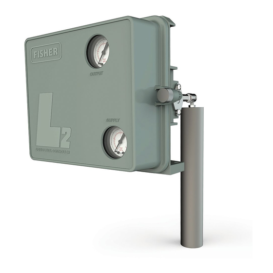
W8345
Figure 1. Type L2 Liquid Level Controller
6
7
7
7
Introduction
7
Scope of Manual
8
This instruction manual includes installation,
8
adjustment, maintenance, and parts ordering
8
information for Type L2 liquid level controllers.
8
Only personnel qualified through training or
experience should install, operate and maintain this
controller. If there are any questions regarding the
instructions in this manual, contact your Fisher sales
office before proceeding.
Description
The rugged Type L2 liquid level controllers use a
displacer type sensor (see figure 1) to detect liquid
level or the interface of two liquids of different
specific gravities.
Type L2
Advertisement
Table of Contents

Related Manuals for Emerson Fisher l2


Summary of Contents for Emerson Fisher l2
-
Page 1: Table Of Contents
Instruction Manual Form 5732 Type L2 December 2001 Type L2 Liquid Level Controllers Contents Introduction ......Scope of Manual . - Page 2 Instruction Manual Form 5732 Type L2 December 2001 Table 1. Specifications Available Configurations Snap-Acting Controller: Any desired pressure between 1.4 and 5.2 bar (20 and 50 psig) direct, Controllers: Snap-acting or throttling and 1.4 bar and 2.4 bar (20 and 35 psig) reverse Sensor: Displacer-type liquid level sensor for Do not use supply pressure below 1.4 bar (20 mounting to side of tank.
-
Page 3: Specifications
Instruction Manual Form 5732 Type L2 December 2001 These low-bleed controllers use a single four-mode relay to provide the applicable control and action. The device delivers a pneumatic output signal to a control valve. Specifications CORRECT CONTROLLER MOUNTING Specifications for the controller and sensor are listed HOLE ORIENTATION WHEN in table 1. -
Page 4: Pressure Connections
Instruction Manual Form 5732 Type L2 December 2001 Pressure Connections be relied upon to remove all hazardous gas. Vent line piping should comply with local and regional WARNING codes and should be as short as possible with adequate inside diameter and few bends to reduce Personal injury or property damage may case pressure buildup. - Page 5 Instruction Manual Form 5732 Type L2 December 2001 SWITCH RETENTION SCREWS SWITCH RETENTION SCREWS DIRECT ACTION THROTTLING DIRECT ACTION ON/OFF CONTROL MODE CONTROL MODE REVERSE ACTION THROTTLING REVERSE ACTION ON/OFF CONTROL MODE CONTROL MODE NOTE: ALL FOUR SWITCH RETENTION SCREWS SHOWN ONLY ON THIS VIEW. OTHER VIEWS SHOW ONLY TWO SWITCH RETENTION SCREWS IN ORDER TO ILLUSTRATE THE SWITCH CONFIGURATION.
-
Page 6: Preliminary Checks
Instruction Manual Form 5732 Type L2 December 2001 LEVER A SPAN LEVER GAP LEVER B MOST SENSITIVE POSITION FOR THROTTLING AND ON/OFF CONTROLLER. LEAST SENSITIVE POSITION FOR SNAP-ACTING CONTROLLER LEVER A CONTACTING THE DISPLACER ROD LEAST SENSITIVE POSITION FOR THROTTLING AND ON/OFF CONTROLLER. MOST SENSITIVE POSITION FOR SNAP-ACTING CONTROLLER GB0137–2 E0787... -
Page 7: Reverse-Acting Throttling Controllers
Instruction Manual Form 5732 Type L2 December 2001 operating point on the displacer. For interface 2. Lower the liquid level so that it is below the applications, completely cover the displacer with the bottom of the displacer or at the lowest desired lighter fluid. -
Page 8: Maintenance
Instruction Manual Form 5732 Type L2 December 2001 LEVER B DISPLACER ROD PROPORTIONAL RELAY BAND ADJUSTMENT PIVOT POINT O ZERO SPRING LEVER A DISPLACER A5592 / IL Figure 6. Operational Schematic Maintenance Removing the Controller From the Sensor Parts are subject to normal wear and must be inspected periodically and replaced as necessary. - Page 9 Instruction Manual Form 5732 Type L2 December 2001 VIEW SECTION A A VIEW B GB0139–A Figure 7. Sensor...
-
Page 10: Assembly
Instruction Manual Form 5732 Type L2 December 2001 Remove the hex nut (key 67) to permit removing the 7. Slide the spring (key 68) and spacer (key 66) displacer rod, pivot base, pivot body, and spacer onto the displacer rod and secure with the hex nut from the sensor connection. - Page 11 Instruction Manual Form 5732 Type L2 December 2001 THROTTLING AND ON/OFF CONTROLLER RELAY ASSY THROTTLING AND ON/OFF CONTROLLER SNAP-ACTING VIEW A A CONTROLLER RELAY ASSEMBLY SNAP ACTING CONTROLLER j APPLY LUB/SEALANT GB0137–2 Figure 8. Type L2 Liquid Level Controllers...
-
Page 12: Parts Kits
*Recommended spare parts Fisher is a mark owned by Fisher Controls International, Inc., a business of Emerson Process Management. The Emerson logo is a trademark and service mark of Emerson Electric Co. All other marks are the property of their respective owners.
Need help?
Do you have a question about the Fisher l2 and is the answer not in the manual?
Questions and answers