
Subscribe to Our Youtube Channel
Related Manuals for Emerson FPCSK


Summary of Contents for Emerson FPCSK
- Page 1 FPCSK and FPCBA Electronic Bypass Controller NSTRUCTION ANUAL TART UIDE Part Number: 027–2201 Issue: 1.1 ...
- Page 2 The information contained within this document is proprietary to Emerson Control Techniques and may not be copied, reproduced or transmitted to other parties without the expressed written consent of Emerson Control Techniques.
-
Page 3: Table Of Contents
2.4 Mounting & Clearances ..................... 3 2.5 Wiring and Precautions ..................... 4 2.5.1 General ......................... 4 2.5.2 Input Wiring ........................ 4 2.5.3 Output Wiring ....................... 5 2.5.4 Control Circuit Wiring (FPCSK) ................ 7 2.5.5 Control Circuit Wiring (FPCBA) ................ 8 2.5.6 Grounding ........................ 10 2.6 Inspection .......................... 10 2.7 Checking Motor Rotation .................... 10 ... - Page 4 Chapter 7 - Appendix ......................... 30 7.1 Specifications ........................ 30 7.1.1 Electronic bypass ...................... 30 7.2 Maintenance & Inspection .................... 31 7.3 Start-up Checklist – Electronic Bypass ................. 32 7.4 Startup Checklist – VFD .................... 33 Chapter 8 ............................. 34 8.1 FPCSK Schematic ...................... 34 8.2 FPCBA Schematic ...................... 35 ...
-
Page 5: Chapter 1 - Introduction
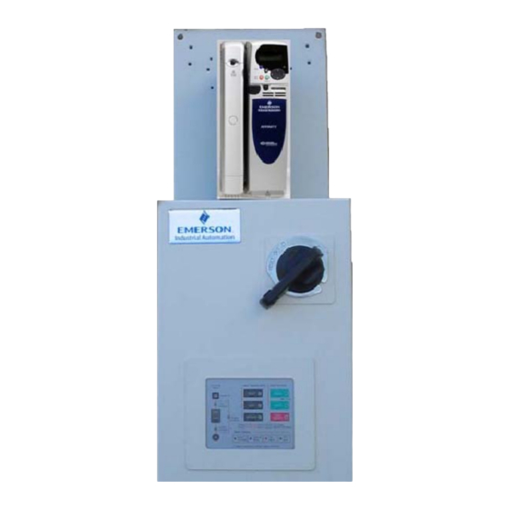
FPCSK and the FPCBA lines of Electronic bypass packages. The Electronic bypass is a complete integrated HVAC control system, which employs the latest Variable Frequency Drive (VFD) technology and incorporates a dedicated micro-processor based controller for HVAC applications. -
Page 6: Chapter 2 - Installation Instructions
√ Check the unit for physical damage which may have occurred during shipping. If any part of the package is missing or damaged. Notify the carrier and your Emerson Control Techniques representative immediately. √ Verify that all internal hardware (i.e. components, screws, etc.) is properly seated and fastened securely. - Page 7 VFD Labels Typical Standard VFD Rating Label Typical VFD Approvals Label 1 ...
-
Page 8: Part Number Identification
2.3 Part Number Identification 2 ... -
Page 9: Mounting & Clearances
2.4 Mounting & Clearances Install the Electronic bypass package on a vertical surface and allow the following minimum clearances for normal heat dissipation. Notes: • Ambient operating temperature; 32°F to 104°F ( 0°C to 40°C) • Install the unit in a dry environment free from oil mist and dust •... -
Page 10: Wiring And Precautions
2.5 Wiring and Precautions 2.5.1 General 1. DO NOT connect or disconnect wiring, or perform signal checks while the power supply is turned ON. Connect the power supply wiring to the Electronic bypass input terminals L1, L2 and L3 on the main circuit disconnect device. -
Page 11: Output Wiring
2.5.3 Output Wiring The Electronic bypass package is always supplied with a Class 20 motor O/L on its output. However, the unit may be supplied with several different output options. The following output options are available. • Single motor O/L (Terminals T1, T2, and T3) •... - Page 12 Note: All contactors and relays supplied in the Electronic bypass package are suppressed with R/C snubbers. If adding additional inductive loads (i.e. magnetic contactors, magnetic relays, magnetic valves, solenoids, magnetic brakes, etc.) in or near the Electronic bypass package use an appropriate surge suppressor across the coils to limit the transients on the supply lines.
-
Page 13: Control Circuit Wiring (Fpcsk)
2.5.4 Control Circuit Wiring (FPCSK) 2.5.4.1 Analog Output A 0-10 Vdc analog output signal is available by connecting to Commander HSK control terminals B1 (+) and T1 (-). The default is output frequency. 2.5.4.2 Digital Input The Electronic bypass combines digital inputs from the Commander HSK inverter and the Electronic bypass control board to allow maximum flexibility. -
Page 14: Control Circuit Wiring (Fpcba)
Commander HSK inverter. These connections are made at the factory and are for reference only. Do not change this wiring as it will cause the Electronic bypass to operate improperly or not at all. Electronic bypass control Wire FPCSK Board number J11 – 1 Motor overload relay J11 –... - Page 15 2.5.5.3 Digital / Relay Outputs There are four (4) Form A relay outputs rated 125 Vac, 0.5 A on the Electronic bypass control board. Terminal No. Description TB1-1 & TB1-2 Power On TB1-3 & TB1-4 Fault TB1-5 & TB1-6 Damper actuator TB1-7 &...
-
Page 16: Grounding
2.5.6 Grounding Never ground the Electronic bypass package in common with welding machines, motors, or other high current electrical equipment. Run all ground wires in a separate conduit. When using several Electronic bypass packages side by side, ground as shown below. -
Page 17: Check #1: Rotation On Vfd Power
2.7.1 Check #1: Rotation on VFD power Place the VFD package in HAND (local) control by pressing the VFD and HAND push buttons of the Electronic bypass keypad. The VFD, HAND, input and output contactor LEDs will be illuminated. The VFD must be started and stopped by the start/stop buttons on the VFD keypad. -
Page 18: Chapter 3 - Overview Of The Electronic Bypass
Chapter 3 – Overview of the Electronic bypass All start/stop, safety, and Fire Alarm inputs are routed to the Electronic bypass control board via customer terminal connections. The VFD analog output is directly connected to the VFD control terminals. The Electronic bypass control card is factory set to accept a sinking type (dry contact closure) type input. - Page 19 Electronic Bypass Control Functions TYPE LOCATION DESCRIPTION SIGNAL LEVEL/RATING 120 Vac single phase (neutral) Input Power 120 Vac Single Phase 120 Vac single phase (hot) Input Contactor Contactor Bypass Contactor Outputs Output Contactor Motor Overload Input 24 Vdc upon overload Drive Fault Input 24 Vdc upon fault 24 Vdc Common to VFD...
-
Page 20: Using The Electronic Bypass Configuration Switches
3.3 Using the Electronic Bypass Configuration Switches The bypass configuration switches are a group of four switches that are used to tailor the Automatic Bypass Fire Alarm Damper Control Fireman’s Override Switch 1: Enables or disables the automatic bypass function. With switch 1 in the ON position, and the electronic bypass package operating in VFD mode, a VFD fault will cause both the operation and run modes to be cancelled (stopping the motor) and the VFD Fault LED to illuminate in the... -
Page 21: Using The Additional Customer Inputs
bypass controller must see the customer “damper feedback” contact closed (TB3-3) within that time to prevent the bypass controller from “faulting” and preventing motor operation. The Bypass Keypad will annunciate the faulted condition by flashing one or more of the button status LEDs that happened to be on at the time of the fault. -
Page 22: Alarm Displays
selections and force the Electronic bypass into bypass mode from an external contact. Once this signal is removed, the Electronic bypass will not return to its’ previous mode of operation without keypad interaction. Remote VFD input (TB3-2): works just like the remote bypass input, by forcing the Electronic bypass into VFD mode. -
Page 23: Vfd Mode
To exit the TEST mode, press the OFF/RESET button on the ELECTRONIC BYPASS keypad. The VFD input contactor will open and the TEST and input contactor LEDs will go out. 3.7.2 VFD mode In VFD mode both the input and output contactors are energized. A start mode pushbutton must be pressed before the VFD can operate. -
Page 24: Auto Mode
3.7.5 AUTO mode In the VFD AUTO (automatic mode), a building automation system or other external device is required to supply start/stop and speed reference information to the Electronic bypass package. During AUTO mode operation, the Electronic bypass keypad remains enabled for stopping, operation mode, and bypass selection functions. - Page 25 To exit the BYPASS mode, Press the OFF/RESET button on the Electronic bypass keypad. 3.8.2 AUTOMATIC Bypass on VFD Fault In the Automatic bypass on VFD fault mode of operation, when the Electronic bypass control board senses a VFD fault it will automatically switch the motor to BYPASS operation.
-
Page 26: Chapter 4 - Programming
Electronic bypass package. These settings are pre-programmed from the factory, DO NOT change any of these values unless directed to by Emerson Control Techniques technical support. Note these parameters must be programmed in the sequence shown. -
Page 27: Affinity Recommended Programming
8.22 T25 digital I/O 2 source/destination 10.33 10.33 menu.param 8.23 T26 digital I/O 3 source/destination 6.30 6.30 menu.param 8.24 T27 digital I/O 4 source/destination 1.54 1.54 menu.param 8.25 T28 digital I/O 5 source/destination 1.41 1.41 menu.param 9.04 Logic function 1 source 1 8.03 8.03 menu.param... - Page 28 Menu 0 Setting Units Parameter Description Equivalent Pump Maximum set 1.06 0.02 60.0 60.0 speed Minimum set 1.07 0.01 15.0 speed Acceleration rate 2.11 0.03 100.0 16.6 s/100 Hz Deceleration rate 2.21 0.04 100.0 16.6 s/100 Hz Motor rated 5.07 0.46 From Motor current...
-
Page 29: Chapter 5 - Operation
Chapter 5 - Operation Precautions: 1. Motor rotation MUST be checked in both VFD and Bypass modes. Failure to confirm rotation may cause severe damage to the Electronic bypass, motor or its driven equipment. 2. Only turn ON the input power supply after closing the front door. 3. -
Page 30: Keypad Operation
5.1 Keypad Operation The Electronic bypass package utilizes two keypads in its operation. The VFD Keypad controls the speed in the HAND mode using the up and down arrow keys. In AUTO mode the user supplied 4–20 mA speed reference is connected to speed reference input (Affinity terminals 7–11, HSK terminals T2–T1). -
Page 31: System Status Leds
5.1.3 Electronic B Bypass Keyp ad Layout There are four (4) ma ain sections s of the Elec ctronic bypa ass keypad ystem statu us LEDs AND / OFF F / AUTO bu uttons EST / VFD /BYPASS b buttons larm LED d display 5.1.4... -
Page 32: Test / Vfd / Bypass Buttons
1. HAND mode – (Local) Control via the bypass and VFD keypads 2. AUTO mode – (Remote) Control via terminal connections 3. OFF/RESET mode – Stops either HAND or AUTO operation 5.1.6 TEST / VFD / BYPASS Buttons There are three (3) buttons used to select the three modes of operation available. -
Page 33: Ending Operation
5.3 Ending Operation There are two (2) options available for ending operation 1 - Press OFF/RESET button once – Cancels the start mode of operation. 2 - Press OFF/RESET button twice – Cancels the operation mode. 27 ... -
Page 34: Chapter 6 - Alarm & Faults
Chapter 6 - Alarm & Faults There are two different locations a fault or alarm will be displayed: The Electronic bypass keypad The VFD keypad 6.1 Electronic Bypass Keypad Alarms and Faults There are four (4) Alarm LEDs on the Electronic bypass keypad indicating the faults that may occur. - Page 35 Commander SK Advanced User Guide or the Affinity User Guide for detailed fault information including possible causes and remedies. 29 ...
-
Page 36: Chapter 7 - Appendix
Chapter 7 - Appendix 7.1 Specifications 7.1.1 Electronic bypass The Electronic bypass package features a user friendly application specific keypad to simplify operation and provide status indication. Approvals: VFD Section – UL508C Bypass Section – UL508A Design: 3 contactor bypass NEMA 1 enclosure Electronic bypass keypad / annunciator panel 32-bit Microprocessor... -
Page 37: Maintenance & Inspection
Options: Input fused disconnect Input circuit breaker Input or output reactors Dual motor overloads Input RFI filter Metasys N2 (Affinity BA only) LONworks Ethernet 7.2 Maintenance & Inspection This section describes the basic periodic maintenance and inspection procedures for the Electronic bypass. Caution! To prevent electrical shock and damage, disconnect all power before servicing the Electronic bypass package. -
Page 38: Start-Up Checklist - Electronic Bypass
7.3 Start-up Checklist – Electronic Bypass Motor rotation MUST be checked in both VFD and Bypass modes. Failure to confirm rotation may cause severe damage to the Electronic bypass, motor or its driven equipment. Pre-Power checks Confirm proper operating voltage: [ ] 208 V [ ] 230 V [ ] 460 V... -
Page 39: Startup Checklist - Vfd
7.4 Startup Checklist – VFD Customer: Installation Site: Date: Sales Order #: Service Order #: Serial#: Model #: Application Description: Checklist (Note any discrepancy in checklist findings in comment field) Unit ready for startup with all connections made and control interface, power and load available? Enclosure inspected for shipping damage, physical integrity;... -
Page 40: Chapter 8
Chapter 8 8.1 FPCSK Schematic 34 ... -
Page 41: Fpcba Schematic
8.2 FPCBA Schematic 35 ... - Page 42 NOTES: 36 ...
- Page 43 Part Number 027-2201 Issue 1.1 © Control Techniques Americas LLC 2009 37 ...
Need help?
Do you have a question about the FPCSK and is the answer not in the manual?
Questions and answers