Emerson Fisher 627 Instruction Manual
627 series pressure reducing regulators
Hide thumbs
Also See for Fisher 627:
- Manual (26 pages) ,
- Instruction manual (24 pages) ,
- Instruction manual (20 pages)
Table of Contents
Advertisement
Instruction Manual
Form 5252
May 2013
627 Series Pressure Reducing Regulators
WARNING
!
Failure to follow these instructions or
to properly install and maintain this
equipment could result in an explosion
and/or fire causing property damage and
personal injury or death.
Fisher
®
regulators must be installed,
operated, and maintained in accordance
with federal, state, and local codes, rules
and regulations, and Emerson Process
Management Regulator Technologies, Inc.
(Regulator Technologies) instructions.
If the regulator vents gas or a leak
develops in the system, service to the unit
may be required. Failure to correct trouble
could result in a hazardous condition.
Call a gas service person to service the
unit. Only a qualified person must install
or service the regulator.
Introduction
Scope of the Manual
This manual provides instructions for the installation,
adjustment, maintenance, and parts ordering information
for the 627 Series regulators. These regulators are
usually shipped separate for line installation, although
sometimes they are shipped installed on other
equipment. Refer to the Instruction Manual of the other
equipment for installation and operating instructions.
Description
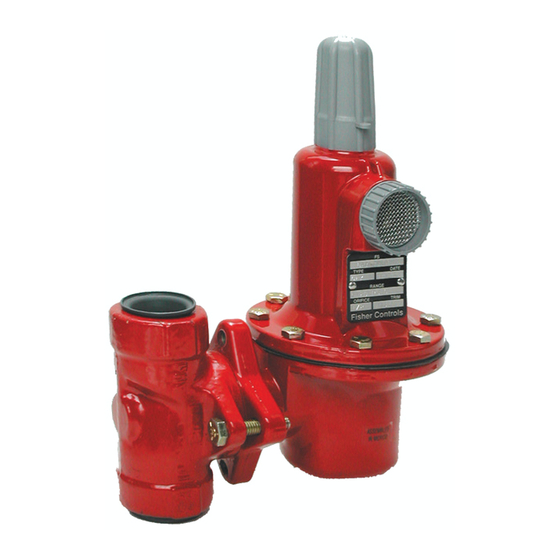
The 627 Series direct-operated pressure reducing
regulators (Figure 1) are for high and low pressure
systems. These regulators can be used with natural
gas, air, or a variety of other gases. Performance
characteristics vary according to construction.
W4793
Personal injury, property damage,
equipment damage, or leakage due to
escaping gas or bursting of pressure-
containing parts may result if this
regulator is overpressured or is installed
where service conditions could exceed
the limits given in the Specifications
section, Tables 1, 2, 3, and 4, or where
conditions exceed any ratings of the
adjacent piping or piping connections.
To avoid such injury or damage, provide
pressure-relieving or pressure-limiting
devices (as required by the appropriate
code, regulation, or standard) to prevent
service conditions from exceeding
www.fisherregulators.com
627 Series
Figure 1. Typical 627 Direct-Operated
Pressure Reducing Regulator
WARNING
!
Advertisement
Table of Contents

Related Manuals for Emerson Fisher 627


Summary of Contents for Emerson Fisher 627
- Page 1 ® regulators must be installed, operated, and maintained in accordance with federal, state, and local codes, rules and regulations, and Emerson Process Management Regulator Technologies, Inc. (Regulator Technologies) instructions. If the regulator vents gas or a leak develops in the system, service to the unit may be required.
- Page 2 627 Series Specifications The Specifications section gives some general specifications for the 627 Series regulators. The nameplates give detailed information for a particular regulator as it comes from the factory. Available Constructions (1)(2) Maximum Body outlet Pressure (Types 627M, 627MR, and 627HM only) Type 627: Direct-operated pressure reducing NPT Steel: 2000 psig / 138 bar regulator equipped with a pitot tube for greater...
- Page 3 627 Series ADjuSTING SCREW CoNTRoL SPRING STEM DIAPHRAGM vALvE DISK PuSHER PoST LEvER A6557 oRIFICE INLET PRESSuRE INLET PRESSuRE ouTLET PRESSuRE ouTLET PRESSuRE ATMoSPHERIC PRESSuRE ATMoSPHERIC PRESSuRE INLET PRESSuRE Figure 2. Type 627 Operational Schematic ouTLET PRESSuRE ATMoSPHERIC PRESSuRE those limits. The Type 627R, 627LR, Product Description or 627MR regulator with internal relief will provide downstream overpressure...
- Page 4 627 Series Table 1. Maximum Inlet Pressures and Outlet Pressure Ranges ouTLET PRESSuRE MAxIMuM INLET PRESSuRE oRIFICE SIzE RANGE, SPRING PART TyPE Nylon (PA) Disk Nitrile (NBR) Disk Fluorocarbon (FKM) Disk NuMBER, AND Inches psig psig psig CoLoR CoDE 3/32 2000 1000 69.0...
- Page 5 627 Series Table 2. Maximum Spring and Diaphragm Casing Pressure TyPES 627R TyPES 627H TyPE 627 TyPE 627M TyPE 627MR DIAPHRAGM AND 627LR AND 627HM MAxIMuM PRESSuRE DESCRIPTIoN CASING MATERIAL psig psig psig psig psig Die cast aluminum Not Available Maximum pressure to spring and diaphragm Not Available Not Available...
- Page 6 627 Series vENT vALvE GRAvITy FEED ALCoHoL DRIP PoT TyPE 627M SET LoWER THAN WoRKING REGuLAToR CoNTRoL LINE NEEDLE HAND vALvE vALvE INLET WoRKING REGuLAToR A3725 Figure 3. De-Icer System Operational Schematic Perform steps 7 through 9 for Types 627M, 627HM, the vent or vent line and prevent proper operation of and 627MR regulators only: the regulator.
- Page 7 627 Series Table 3. Type 627R Internal Relief Performance MAxIMuM MAxIMuM INLET PRESSuRE To KEEP MAxIMuM ALLoWABLE DoWNSTREAM ouTLET ouTLET ALLoWABLE SySTEM PRESSuRE FRoM BEING ExCEEDED PRESSuRE RANGE, PRESSuRE DoWNSTREAM Orifice Size, Inches / mm SPRING PART SETTING SySTEM NuMBER, AND 3/32 / 2.4 1/8 / 3.2 3/16 / 4.8...
- Page 8 627 Series Table 3. Type 627R Internal Relief Performance (continued) MAxIMuM MAxIMuM INLET PRESSuRE To KEEP MAxIMuM ALLoWABLE DoWNSTREAM (2)(3) ouTLET ALLoWABLE SySTEM PRESSuRE FRoM BEING ExCEEDED ouTLET PRESSuRE RANGE, PRESSuRE DoWNSTREAM Orifice Size, Inches / mm SPRING PART NuMBER, SETTING SySTEM AND CoLoR CoDE...
- Page 9 627 Series Table 5. Flow Coefficients oRIFICE 3/4 NPT NPS 1 / DN 25 BoDy NPS 2 / DN 50 BoDy Wide-open Wide-open Wide-open Wide-open Wide-open Wide-open Inch External External External External External External Relief Sizing Relief Sizing Relief Sizing Relief Sizing Relief Sizing Relief Sizing...
- Page 10 627 Series Refer to Figures 7 through 13 for key number locations. 1. Remove the adjusting screw cap (key 36). 2. Loosen the locknut (key 34). 3. Increase the outlet pressure setting by turning the adjusting screw (key 35) clockwise. Decrease the outlet pressure setting by turning the adjusting RELIEF INDICAToR...
- Page 11 627 Series HAIR PIN CLIP (KEy 13) LEvER DIAPHRAGM CASING STEM (KEy 10) (KEy 15) o-RING (KEy 4) BoDy DISK (KEy 1) ASSEMBLy (KEy 9) STEM BACK-uP STEM GuIDE RINGS (KEy 8) (KEy 12) SCREW (KEy 3) BooST BoDy PIToT TuBE DIAPHRAGM STABILIzER STEM o-RING...
- Page 12 627 Series DIAPHRAGM (KEy 23) DIAPHRAGM RELIEF vALvE o-RING HEAD (KEy 24) (KEy 28) PuSHER PoST DIAPHRAGM CoNNECToR (KEy 19) NuT (KEy 22) RELIEF vALvE SPRING (KEy 27) GuIDE RETAINER o-RING (KEy 48) GuIDE RETAINER RELIEF SEAL W4668 RELIEF SPRING LoWER SPRING (KEy 26) DIAPHRAGM CoNNECToR...
- Page 13 627 Series 19. Secure the diaphragm casing (key 5) to the body Perform steps 6 through 11 for Types 627, 627H, with the cap screws (key 3, Figure 5). For an 627M, and 627HM Regulators only: aluminum diaphragm casing, torque the cap screws 6.
- Page 14 627 Series 15. Position the replacement diaphragm (key 23) Parts ordering on the connector assembly (key 21), install the When corresponding with your local Sales Office about diaphragm head (key 24) and connector nut (key 22), then torque to 17 foot-pounds / 23 N•m. this equipment, always reference the equipment serial number or FS number that can be found on 16.
- Page 15 627 Series Description Part Number Description Part Number Diaphragm Case O-ring Body (continued) Steel, CL150 RF flanged Nitrile (NBR) 290 psig / 20.0 bar maximum inlet pressure For Type 627, 627H, or 627R only 17A2325X022 NPS 1 / DN 25 43B8656X022 Fluorocarbon (FKM) NPS 2 / DN 50...
- Page 16 627 Series Description Part Number Description Part Number Lever Cap Screw (2 required) Screened Vent Assembly, Plastic 10B3093X012 Plated steel 10B7454X012 Lower Spring Seat, Plated steel 316 Stainless steel (NACE) 1B2905X0012 For Type 627 or 627M 1D666625072 Pusher Post, Aluminum For Type 627R, 627LR, or 627MR 20B3073X012 For Type 627 or 627M...
- Page 17 627 Series 30B3092_G APPLy LuBRICANT L1 = MuLTI-PuRPoSE LITHIuM PoLyMER TyPE GREASE L2 = ExTREME LoW-TEMPERATuRE BEARING GREASE PARTS NoT SHoWN: 3 1. Lubricants must be selected such that they meet the temperature requirements. Figure 7. Type 627 Regulator Assembly...
- Page 18 627 Series 26 32 18 29 34 36 35 14 17 30B3089_G APPLy LuBRICANT L1 = MuLTI-PuRPoSE LITHIuM PoLyMER TyPE GREASE L2 = ExTREME LoW-TEMPERATuRE BEARING GREASE PARTS NoT SHoWN: 3 1. Lubricants must be selected such that they meet the temperature requirements. Figure 8.
- Page 19 627 Series 29 34 36 35 33 26 32 18 38B4843_C APPLy LuBRICANT L1 = MuLTI-PuRPoSE LITHIuM PoLyMER TyPE GREASE L2 = ExTREME LoW-TEMPERATuRE BEARING GREASE PARTS NoT SHoWN: 3 1. Lubricants must be selected such that they meet the temperature requirements. Figure 9.
- Page 20 627 Series 16 11 12 10 13 14 17 30B6433_E APPLy LuBRICANT L1 = MuLTI-PuRPoSE LITHIuM PoLyMER TyPE GREASE L2 = ExTREME LoW-TEMPERATuRE BEARING GREASE PARTS NoT SHoWN: 3 1. Lubricants must be selected such that they meet the temperature requirements. Figure 10.
- Page 21 627 Series 34 36 35 33 26 32 18 30B6434_E APPLy LuBRICANT L1 = MuLTI-PuRPoSE LITHIuM PoLyMER TyPE GREASE L2 = ExTREME LoW-TEMPERATuRE BEARING GREASE PARTS NoT SHoWN: 3 1. Lubricants must be selected such that they meet the temperature requirements. Figure 11.
- Page 22 627 Series 14 17 31B5374_D APPLy LuBRICANT L1 = MuLTI-PuRPoSE LITHIuM PoLyMER TyPE GREASE L2 = ExTREME LoW-TEMPERATuRE BEARING GREASE PARTS NoT SHoWN: 3 1. Lubricants must be selected such that they meet the temperature requirements. Figure 12. Type 627H Regulator Assembly...
- Page 23 627 Series 14 17 31B9872_D APPLy LuBRICANT L1 = MuLTI-PuRPoSE LITHIuM PoLyMER TyPE GREASE L2 = ExTREME LoW-TEMPERATuRE BEARING GREASE PARTS NoT SHoWN: 3 1. Lubricants must be selected such that they meet the temperature requirements. Figure 13. Type 627HM Regulator Assembly...
- Page 24 For further information visit www.fisherregulators.com The Emerson logo is a trademark and service mark of Emerson Electric Co. All other marks are the property of their prospective owners. Fisher is a mark owned by Fisher Controls International LLC, a business of Emerson Process Management.
Need help?
Do you have a question about the Fisher 627 and is the answer not in the manual?
Questions and answers