Table of Contents
Advertisement
Advertisement
Table of Contents

Related Manuals for B&G Triton Display


Summary of Contents for B&G Triton Display
- Page 1 Triton Display Installation Manual ENGLISH bandg.com...
-
Page 3: Preface
Used to draw the reader’s attention to a comment or some important information. Warning: Used when it is necessary to warn personnel that they should proceed carefully to prevent risk of injury and/or damage to equipment/personnel. Preface | B&G Triton Display Installation Manual... -
Page 4: About This Manual
B&G Triton Display complies with the following regulations: • CE under EMC directive 2004/108/EC • level 2 devices of the Radio communications (Electromagnetic Compatibility) standard 2008 B&G Triton Display meets the technical standards in accordance with Part 15.103 of the FCC rules. About this manual This manual is a reference guide for installing the B&G Triton system. - Page 5 The manual may have been updated to match new software releases. The latest available manual version can be downloaded from www.bandg.com ¼ Note: Portions of this software are copyright © 2011 The FreeType Project (www.freetype.org). All rights reserved. Preface | B&G Triton Display Installation Manual...
-
Page 7: Table Of Contents
Check the contents Installation Choosing a location Viewing angles Fitting with mounting clip Fitting with retention bracket Multiple displays Wiring Introduction to NMEA 2000 (SimNet) Daisy chaining the Triton display Drop cable connection of the Triton display Typical network example Display Setup wizard Sources Calibration Depth Sea temperature Boat speed... -
Page 8: Contents
Autopilot Autopilot Setup Dockside Sea trial Pilot response Wind response Sea state filter Sailing Automatic steering Troubleshooting Technical Specifications Display Dimensional drawing Spares & Accessories Contents | B&G Triton Display Installation Manual... -
Page 9: Introduction
Power consumption is extremely low for this class of product - 155 mA at 13.5 V with backlight driven at full brightness. Dual Micro-C connectors provide for quick and easy daisy-chain connection - ideal for retrofit or new build. Micro-C is the industry standard cabling used for NMEA 2000 systems. Introduction | B&G Triton Display Installation Manual... -
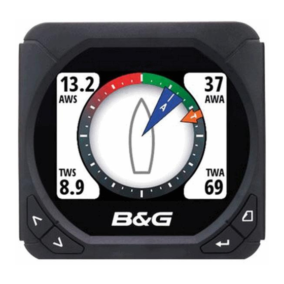
Page 10: Overview
Overview The Triton Display and Pilot Controller Display Menu / Enter key Used to enter the main menu, select sub menus and confirm selection. ¼ Note: Press and holding the Enter key for 3 seconds takes you directly to the display setup lighting level screen. If the lighting level is set below 5 it will automatically increase to 5. -
Page 11: Menus
Under normal operation, the unit will power up displaying the most recently used data page. To enter the menu use the Menu/Enter key. Current menu Selection highlight Indication for more content off page Menu expands to further level of detail Overview | B&G Triton Display Installation Manual... -
Page 12: Check The Contents
Check the contents Triton Instrument Display Mounting Clip Sun Cover Fixing Screws Additional Retention Bracket Threaded rods, Washers, and Fasteners for Retention bracket 0.6m Interconnect Cable (Micro-C) - Straight connectors 10 | Overview | B&G Triton Display Installation Manual... - Page 13 중요: 복사나 출력으로 크기가 조정 된 경우 이 템플릿을 사용하지 마십시오. 원본이 아니거나 인쇄물이면, 사용하기 전 아래 치수선의 눈금을 확인 해 주십시오. 注:このテンプレ トは印刷やコピ によって縮尺が わっていることがあり 150 mm ますので使用しないで下さい。テンプレ トがオリジナルのものでない場合に は、下の寸法線を使って縮尺を確認してください。 Warranty Booklet | 11 Overview | B&G Triton Display Installation Manual...
-
Page 14: Installation
Installation The Triton display may be mounted via a flush mounting clip or with the retention bracket attached to the rear of the unit. Choosing a location Choose the mounting locations carefully before you drill or cut. The display should be mounted so that the operator can easily use the controls and clearly see the display screen. -
Page 15: Fitting With Mounting Clip
The display can then be fitted by pressing into the mounting clip aperture - a positive ‘click’ should be felt when the display engages with the clip. Check that all four edges of the display make good contact with the mounting surface, and apply adequate compression to the gasket. | 13 Installation | B&G Triton Display Installation Manual... - Page 16 Fitting with retention bracket The Triton display may be mounted using only the mounting clip, or may be secured additionally with the retention bracket. In order to secure the bracket, adequate rear access must be available to fit the fasteners.
-
Page 17: Wiring
Wiring The B&G Triton Display can be connected to either an NMEA2000 or SimNet network. There is no separate power cable, as the unit is powered from the network. There are two Micro-C connectors on each display, allowing for daisy chaining, which greatly increases the ease of connecting multiple displays that are in close proximity, and can save in cable weight and loom size. - Page 18 Wind transducer. If using a wind sensor, plan to connect this to one end of the backbone as this has a terminator built in • Micro-C male and Micro-C female to SimNet adaptor cables for connecting to existing SimNet bus, or adding devices fitted with a SimNet connector to a Micro-C network. 16 | Wiring | B&G Triton Display Installation Manual...
-
Page 19: Daisy Chaining The Triton Display
Avoid connection to the engine starting batteries where possible. Daisy chaining the Triton display Where displays are located close together, the supplied right angle Micro-C cable may be used to link the displays in series. The daisy chain should form part of the back bone. It is not advisable to daisy chain devices off a drop cable. - Page 20 Drop cable connection of the Triton display Triton Display Drop cable NMEA2000 / SimNet backbone Micro-C T-connectors 18 | Wiring | B&G Triton Display Installation Manual...
-
Page 21: Typical Network Example
Typical network example | 19 Wiring | B&G Triton Display Installation Manual... -
Page 22: Display
This section focuses on initial setup of settings that should require infrequent adjustment. For regularly used features, refer to the Operation or Quick Guide. Setup wizard The first time a new Triton display is turned on, the Setup Wizard will guide you through essential configuration items. • Language •... - Page 23 Once complete select Save to save your settings and exit. ¼ Note: Local time is calculated based on UTC provided via a GPS unit connected to the network. | 21 Display | B&G Triton Display Installation Manual...
- Page 24 If magnetic variation is not available via a GPS an offset can be entered manually. See Magnetic variation for more information. The same applies if the user wants to read magnetic heading, but only receives true heading from the compass. 22 | Display | B&G Triton Display Installation Manual...
-
Page 25: Display Mode
Possible to view instrument data pages at all times and Pilot data when a Pilot system is installed and connected to the network. ¼ Note: The Pilot page is automatically displayed when the Pilot is engaged. | 23 Display | B&G Triton Display Installation Manual... -
Page 26: Software Information
We recommend that you use this diagnostic tool as a basic overview of the network status. For more detailed information it is suggested that you check the individual source information via the device list. 24 | Display | B&G Triton Display Installation Manual... - Page 27 Warning: The Pilot will need to be commissioned before it is fit for purpose. Do not engage the autopilot until it has been commissioned and a sea trial has been completed. | 25 Display | B&G Triton Display Installation Manual...
- Page 28 The Pilot will need to be commissioned before use. Simulator Simulator mode sends simulated data to the display. Warning: It is not advisable to enter simulator mode when using your instrument system as a navigation aid. 26 | Display | B&G Triton Display Installation Manual...
-
Page 29: Sources
If more than one source is available for each item, the display will automatically select from the internal device priority list. Verify that all interfaced units are powered on Press the ‘Enter’ key to start the auto select procedure | 27 Display | B&G Triton Display Installation Manual... - Page 30 Select the preferred data source. The selected source will be indicated by a tick in the check box. Device list Shows a list of devices connected to the Network. 28 | Display | B&G Triton Display Installation Manual...
- Page 31 For compass sensors only, once installed you will need to calibrate the device. Select Calibrate and follow the instructions on the display. See calibration section of the manual for more information. | 29 Display | B&G Triton Display Installation Manual...
-
Page 32: Calibration
30 | Calibration | B&G Triton Display Installation Manual... -
Page 33: Sea Temperature
¼ Note: This calibration should be made in calm sea with no effect from wind or tidal current. | 31 Calibration | B&G Triton Display Installation Manual... - Page 34 Manual adjustment of boat speed Adjust the boat speed manually by selecting the Boat speed percentage slider. Adjust the percentage up or down as desired. Confirm the value. Select OK once complete. 32 | Calibration | B&G Triton Display Installation Manual...
- Page 35 Enter the desired distance in nautical miles that you would like to calculate the distance reference over. When the boat gets to the predetermined starting position of the distance reference calculation start the calibration timer. | 33 Calibration | B&G Triton Display Installation Manual...
- Page 36 After the last run is completed and OK has been selected, a pop up warning will ask you if you wish to replace the current calibration with the new one. Select Yes to complete. 34 | Calibration | B&G Triton Display Installation Manual...
-
Page 37: Apparent Wind
2 and enter this as a negative offset. If the port angle is greater than the starboard then divide the difference by 2 and enter this as a positive offset. | 35 Calibration | B&G Triton Display Installation Manual... -
Page 38: Compass Heading
The damping rate effects the frequency that the sensor data is updated on the display, the greater the damping value the smoother the number change will be but the slower the response will be to data change. 36 | Calibration | B&G Triton Display Installation Manual... -
Page 39: Magnetic Variation
Silencing the alarm sound does not deactivate the alarms. When an alarm is activated the warning notification will be shown on the display regardless of the sound being on or off. | 37 Calibration | B&G Triton Display Installation Manual... -
Page 40: Autopilot
The Sea trial settings are dependent on successful completion of the Dockside settings. ¼ Note: If you select the Pilot page and the Pilot has not been commissioned you can go straight to the commissioning page by selecting Setup. 38 | Autopilot | B&G Triton Display Installation Manual... -
Page 41: Autopilot Setup
The following menu items are accessible and can be set up in the Installation menu: • Boat type • Rudder feedback • Drive voltage • Drive engage • Rudder test • Depth calibration • Minimum wind angle • Nav change limit | 39 Autopilot | B&G Triton Display Installation Manual... - Page 42 Manually move the helm to port until the rudder stops at port lock hard over. • Adjust the displayed angle the same way as for starboard rudder. • Confirm Rudder feedback calibration to port by selecting Next. 40 | Autopilot | B&G Triton Display Installation Manual...
- Page 43 It detects minimum power to drive the rudder and reduces the rudder speed if it exceeds the maximum preferred speed (8°/sec.) for autopilot operation. The Rudder test is verifi ed by the display showing Completed Rev. motor, Completed Solenoids, or Failed. If Failed is given, check for correct electrical connection. Also refer to ”Alarms” | 41 Autopilot | B&G Triton Display Installation Manual...
-
Page 44: Automatic Steering
(Maximum speed is used in NFU mode). This setting will allow you to adjust the rudder speed to be different from the one automatically set in the rudder test. 42 | Autopilot | B&G Triton Display Installation Manual... - Page 45 Find the lowest possible value that will prevent the rudder from continuous hunting. A wide deadband will cause inaccurate steering. It is recommended to check rudder stability in Auto mode when the boat is moving to get pressure on the rudder. | 43 Autopilot | B&G Triton Display Installation Manual...
-
Page 46: Sea Trial
The motor Drive Out can be set with the above in mind. Never adjust in more than 10% steps with respect to the reading set during the automatic rudder test. Always perform a new Autotune after the adjustment. 44 | Autopilot | B&G Triton Display Installation Manual... - Page 47 (i.e. if cruising speed is 10 knots, perform the Autotune at about 5 knots). Select Autotune to begin the tuning process. Select yes to confirm Autotune. | 45 Autopilot | B&G Triton Display Installation Manual...
-
Page 48: Pilot Response
When you access the RESPONSE page the highlighted Response parameter is the one that is active. ¼ Note: Adjustment of Hi and Lo values can be performed even with the boat out of the water. 46 | Autopilot | B&G Triton Display Installation Manual... -
Page 49: Wind Response
Wind response to reduce the difference. If the actual wind angle is S-ing around the set wind angle, or the rudder activity is too high, the Wind response should be reduced. Range Change per step Default 1 - 9 | 47 Autopilot | B&G Triton Display Installation Manual... -
Page 50: Sea State Filter
A turn performed without shifting wind side, will also be made at a controlled turn rate. Change per Range Default Units step 2 - 50 Second 48 | Autopilot | B&G Triton Display Installation Manual... -
Page 51: Tack Angle
Default Auto - Apparent - True Auto VMG optimizing Optimizing the VMG to wind will be active for 5–10 minutes after a new wind angle has been set and only when beating. Range Default On - Off | 49 Autopilot | B&G Triton Display Installation Manual... - Page 52 0.15 nm, the autopilot will calculate the layline and track towards the waypoint. XTE will be displayed in the upper left corner above the mode index when layline steering is active Range Default Off - On 50 | Autopilot | B&G Triton Display Installation Manual...
-
Page 53: Automatic Steering
High value parameters for automatic steering at low speed and when running with a sailboat. Low value parameters for automatic steering at high speed and when sailing into the wind or reaching with a sailboat. | 51 Autopilot | B&G Triton Display Installation Manual... - Page 54 Too little Rudder and the autopilot fails to keep a steady course • Too much Rudder gives unstable steering and reduces speed • Low speed requires more rudder than high speed Note: ¼ See also “Minimum Rudder” 52 | Autopilot | B&G Triton Display Installation Manual...
- Page 55 Correct setting of counter rudder, ideal response Autotrim Autotrim standard value is 40 seconds which should work well on most boats. Rule of thumb: Set to same value (seconds) as the boat’s length in feet. Rate limit Should be kept at 6.0°/second unless there is a need for more rapid response in turns. | 53 Autopilot | B&G Triton Display Installation Manual...
- Page 56 Minimum wind angle Port / Starboard The Minimum wind angle is the apparent wind angle that the boat sails to when close hauled. This parameter will vary from boat to boat. 54 | Autopilot | B&G Triton Display Installation Manual...
- Page 57 The limit is adjustable. ¼ Note: Nav change limit screen can also be reached from the Nav mode main screen by pressing the ‘Menu’ key followed by the ‘Mode’ key within 2 seconds. Range Change per Default Units step 10 - 30 º | 55 Autopilot | B&G Triton Display Installation Manual...
- Page 58 Resetting the Pilot Warning: all previous Pilot settings will be lost! Before engaging the Pilot the commissioning and calibration process must be completed. 56 | Autopilot | B&G Triton Display Installation Manual...
-
Page 59: Troubleshooting
• Check network topology and termination rules are correctly implemented. • Disconnect other devices from network, one-by-one, starting with 3rd party devices. | 57 Troubleshooting | B&G Triton Display Installation Manual... -
Page 60: Technical Specifications
White (day mode) / Red Illumination (night mode) Environmental Protection IPX7 Safe distance to compass 0.3 m (1.0 ft.) Temperature Operating 0 to +55 ºC (+32 to +130 ºF) Storage -30 to +70 ºC (-22 to +158 ºF) 58 | Technical Specifications | B&G Triton Display Installation Manual... -
Page 61: Dimensional Drawing
Dimensional drawing 123 mm (4.84") 118 mm (4.64") Suncover outline 17 mm (0.67") 18.9 mm (0.74") 40mm (1.57") | 59 Technical Specifications | B&G Triton Display Installation Manual... -
Page 62: Spares & Accessories
000-10652-001 Triton wind sensor pack with 20 meter mast cable 000-10647-001 Triton wind sensor pack with 35 meter mast cable 000-10613-001 RC42N, Rate compass, micro-c 000-10614-001 Cable, micro-c, right angle interconnect 000-10615-001 Sun cover, Triton display ¼ Note: new accessories are continuously being developed, check with your B&G dealer or on www.bandg.com for details on new products. - Page 64 N2584...
Need help?
Do you have a question about the Triton Display and is the answer not in the manual?
Questions and answers