
Related Manuals for B&G Hydra 2000


Summary of Contents for B&G Hydra 2000
- Page 1 Hydra 2000 User Manual USER MANUAL Premier Way, Abbey Park Romsey, Hampshire, S051 9AQ England Tel: (+44) 01794 518448 Fax: (+44) 01794 518077 www.bandguk.com HB-0844-02...
- Page 2 Hydra 2000 User Manual USER MANUAL CONTENTS Product Liability and Safety Warnings Record of Amendments PART 1 - INTRODUCTION PART 2 - OPERATING INFORMATION PART 3 - CALIBRATION PART 4 - INSTALLATION INFORMATION PART 5 - OPTIONS PART 6 -...
- Page 3 WARNING - NAVIGATION HAZARD The Hydra 2000 is an Electronic Navigation System and is designed to assist in the navigation of your yacht. It is not designed totally replace conventional...
- Page 4 Hydra 2000 User Manual RECORD OF AMENDMENTS Date Amendment Description Signature Number HB-0844-02...
-
Page 5: Table Of Contents
NMEA Full Function Display (FFD) 1.4.2 Standard FFD 1.4.3 20/20 Display 1.4.4 Analogue Indicators 1.4.5 Halcyon Display CALIBRATION DAMPING MENU STRUCTURE ILLUSTRATIONS Fig No Page Typical Hydra 2000 System Block Diagram TABLES Table No Page Function Menu Choices Operational Menu Choices 1-11 HB-0844-02... -
Page 6: Typical Hydra 2000 System Block Diagram
NMEA FFD 0 00 Hydra 2000 Main Processor Network Hull Additional Sensors Sonic Speed Unit Sea and Air Temperature, Heel, Trim, Barometric Pressure and Strain Halcyon 2000 Boat Compass Speed Depth Fig 1.1 - Typical Hydra 2000 System Block Diagram HB-0844-02... -
Page 7: System Description
Hydra 2000 User Manual PART 1 - INTRODUCTION SYSTEM DESCRIPTION The Hydra 2000 is a fully integrated instrumentation system that displays information obtained from various sensors on a choice of displays positioned throughout the yacht. Information is fed from the sensors to a Main Processor. From the information gathered by the sensors the Main Processor distributes information to the various displays via the Fastnet cable. -
Page 8: Expansion Unit
Hydra 2000 User Manual Leeway Heading Corrected for Leeway (Course) True Wind Speed True Wind Angle True Wind Direction Heading on Next Tack or Gybe Pressure Trend In addition, the processor provides four outputs for analogue indicators. Any one of eight different types of analogue indicator can be used on any one of these outputs. -
Page 9: Depth Sensor
The Halcyon 2000 Compass is a high performance electronic fluxgate compass for use on both sailing and power craft. It is intended to be connected to Hercules 2000, Hydra 2000 or HS 2000 instrument systems through the B&G Fastnet Network. -
Page 10: Standard Ffd
Hydra 2000. The NMEA FFD contains a NMEA interface which allows your Hydra 2000 System to be connected to devices such as position fixers, autopilots, chart plotters and radars, etc. from different manufacturers. For example your GPS Plus may be at the chart table, but you require its information to steer by on deck. -
Page 11: Halcyon Display
Part 5 - Options for further details. CALIBRATION Before using the Hydra 2000 for navigational purposes it is important that the system is correctly calibrated for your installation. The calibration process has been simplified as much as possible, so that all you need is accurate information. This is fully explained in Part 3 - Calibration. -
Page 12: Menu Structure
Hydra 2000 User Manual MENU STRUCTURE The central concept to the operation of the system is the structure of the Function Menus accessed through the FFD, and once this is grasped, operation very quickly becomes familiar. The idea of structured layers of menus is one seen everywhere in modern software, and regular computer users will be familiar with this concept. -
Page 13: Function Menu Choices
Hydra 2000 User Manual Table 1.1 - Function Menu Choices FUNCTION MENU CHOICE FUNCTION TEXT Boat Speed BOAT SPD Speed Average Speed AVG SPD Velocity Made Good Stored Log STD LOG Trip Log TRIP LOG Depth - Meters DEPTH M... - Page 14 Hydra 2000 User Manual Table 1.1 - Function Menu Choices (Contd.) FUNCTION MENU CHOICE FUNCTION TEXT Bearing W/point to W/point Mag. BRG W-W M Bearing W/point to W/point True BRG W-W T Bearing to W/point Rhumb Mag. BTW RMB M...
-
Page 15: Operational Menu Choices
Hydra 2000 User Manual Table 1.2 - Operational Menu Choices OPERATION AVAILABLE OPERATIONAL FUNCTION(S) CHOICE Trip Log RESET Log Control D/R Course D/R Distance FREEZE FREEZE START 0 Timer Control Timer START 5 START 10 START 15 PR Trend PR Trend... - Page 16 Hydra 2000 User Manual Table 1.2 - Operational Menu Choice (Contd.) OPERATION AVAILABLE OPERATIONAL FUNCTION(S) CHOICE SINGLE PORT CAL Calibrate Log BOAT SPD STBD CAL (AUTO CAL) STD LOG CAL DIST STRT RUN STOP RUN END CAL Calibrate Log BOAT SPD...
- Page 17 Hydra 2000 User Manual Part 2 - Operating Information PART 2 - OPERATING INFORMATION CONTENTS Para Page FULL FUNCTION DISPLAY (FFD) 2.1.1 The Keys 2.1.2 Power/Lights Key 2.1.3 Page Key 2.1.4 Scroll Keys 2.1.5 Enter/Reset Key 2.1.6 Speed/Depth (SPD/DEP) Key 2.1.7...
- Page 18 Hydra 2000 User Manual Part 2 - Operating Information TRIP FUNCTIONS 2-16 2.8.1 Fast Reset 2-17 2.8.2 Reset Timer 2-17 2.8.3 Reset Trip Log 2-18 LIGHTING CONTROL 2-18 2.9.1 Select Local Control 2-19 2.9.2 Select System Control 2-19 2.10 OPERATING NOTES 2-19 2.11...
-
Page 19: Illustrations
Hydra 2000 User Manual Part 2 - Operating Information CONTENTS (Contd.) Para Page 2.11.30 Speed Over Ground 2-33 2.11.31 Stored Log 2-34 2.11.32 Tidal Set and Drift 2-34 2.11.33 Timer 2-35 2.11.34 Time to Layline 2-36 2.11.35 Time to Waypoint 2-36 2.11.36... -
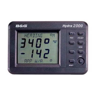
Page 20: Full Function Display (Ffd)
Part 2 - Operating Information PART 2 - OPERATING INFORMATION FULL FUNCTION DISPLAY (FFD) The Hydra 2000 System is easily operated using the keys on any one of the NMEA or Standard Full Function Displays (FFD). Fig 2.1 - Full Function Display The information displayed on each FFD consists of a page of information comprising an upper display and a lower display. -
Page 21: The Keys
Hydra 2000 User Manual Part 2 - Operating Information 2.1.1 The Keys All FFDs are provided with the following eight keys: Power/Lights Key Page Key Scroll Up Key Scroll Down Key Enter/Reset Key Speed/Depth Key Wind Key Navigation Key 2.1.2... -
Page 22: Scroll Keys
Hydra 2000 User Manual Part 2 - Operating Information Notes 1. If you become lost in the system, press the Page Key and you will immediately return to the top level display without doing any damage. 2. Successive operations of the Page Key will bring up each of the user defined pages in rotation. -
Page 23: Speed/Depth (Spd/Dep) Key
Hydra 2000 User Manual Part 2 - Operating Information Expand Function Displays. When displaying the LOG and TIMER functions the Enter Key can be used to expand the display. Normally the Log function displays nautical miles to two decimal places, i.e. 99.99nm (maximum). -
Page 24: Remote Button Operation
The Super Halcyon 3 and Halcyon 2000 Compasses are high performance electronic transmitting compasses which interface with your Hydra 2000 System. Heading and direction information may be selected for display on any of the FFDs or on a Halcyon Display. Additionally, analogue compass card displays may also be added. -
Page 25: Halcyon Display
HALCYON DISPLAY The Halcyon Display is a dedicated electronic compass display that may be connected to your Hydra 2000 System in the same manner as a regular FFD. It is a large digit display providing a clear and accurate digital indication of compass heading information together with a bar graph indicating port and starboard off-course error. -
Page 26: Page Display Configuration
Hydra 2000 User Manual Part 2 - Operating Information Press Enter again, the lower display now shows Stored Log function, the upper display is not affected. At this stage we have simply called up this function to view it, if the Page Key is pressed then the configured page will return and Stored Log will no longer be on view. -
Page 27: Damping Adjustment - Boat Speed
Hydra 2000 User Manual Part 2 - Operating Information (1) Press the Page Key once. (2) Press Scroll Up until the upper display shows CNFG DSP flashing. (3) Press Enter, the upper text now shows PAGE flashing. (4) Press Scroll Up to select either NAV MODE GC (Great Circle) or NAV MODE RH (Rhumb). -
Page 28: Examples Of Calibration
Hydra 2000 User Manual Part 2 - Operating Information EXAMPLES OF CALIBRATION The calibration method of your Hydra 2000 System will be made clear by the following examples. The Calibration Process is described in detail in Part 3 - Calibration. -
Page 29: Calibration Adjustment - Depth
Hydra 2000 User Manual Part 2 - Operating Information 2.6.2 Calibration Adjustment - Depth (1) Using the Scroll Up or Scroll Down Keys select the upper or lower display as required. (2) If DEPTH is shown in the upper display, press and hold the Scroll Down Key to select CALBRATE from the menu. -
Page 30: Alarms
Hydra 2000 User Manual Part 2 - Operating Information (6) Press Page to return to the normal display. ALARMS 2.7.1 Alarm Control When a pre-set alarm parameter is reached, e.g. the depth reducing, the system raises an alarm automatically. In an alarm... -
Page 31: Set Lo Alarm - Depth
Hydra 2000 User Manual Part 2 - Operating Information For example, when the SECTOR alarm is turned on, the alarm reference heading is the current compass heading. If the SECTOR alarm is set at 40° the sector value is the compass heading +/- 20°. -
Page 32: Switch Alarms On/Off
ON again. TRIP FUNCTIONS The Hydra 2000 provides three trip functions - Timer (count up and count down), Trip Log and Dead Reckoning. The functions can be reset and restarted as required, e.g. for keeping a separate log of elapsed time and distance run for a given passage. -
Page 33: Fast Reset
2.8.1 Fast Reset The Hydra 2000 System incorporates a Fast Reset feature for all trip functions (Trip Log, Timer and Barometric Pressure Trend). Fast Reset can be initiated either by operation of a Remote Push- Button (see Para 2.1.9) -
Page 34: Reset Trip Log
Hydra 2000 User Manual Part 2 - Operating Information (4) When the 10 minute gun sounds, press Enter. The display now shows the timer counting down from 10 minutes and the START 5 is flashing. If it is required to correct the timer at the 5 minute gun then this is achieved by pressing Enter again at the 5 minute gun. -
Page 35: Select Local Control
Hydra 2000 User Manual Part 2 - Operating Information 2.9.1 Select Local Control (1) Press and hold Scroll Up or Scroll Down until LIGHTING appears in the text. (2) Press Enter, Scroll Down until LOCAL appears in the text. (3) Press Enter again and the original page display appears. -
Page 36: Operating Functions
Hydra 2000 User Manual Part 2 - Operating Information Each successive selected menu choice will be in capitals, separated by a → symbol. For instance the example in Para 2.5.1, to manually calibrate the log, would be presented as follows: SPEED →... -
Page 37: Apparent Wind Speed
Hydra 2000 User Manual Part 2 - Operating Information The apparent wind angle is the angle between the boat's bow and the wind blowing across deck (at mast height). It is a basic number, useful in its own right like Boat Speed, Heading and Apparent Wind Speed and provides the starting point for the higher level, calculated functions. -
Page 38: Barometric Pressure
Hydra 2000 User Manual Part 2 - Operating Information 2.11.5 Barometric Pressure Menu Heading: MISC Function Text: BAROMETER Update Rate: Once per second Units: Millibars Notes 1. Requires pressure sensor. 2. Offset calibration available. This is essential for the Offshore Sailor, giving not only the instantaneous barometric value but also the important trends towards higher or lower pressure. -
Page 39: Battery Voltage
Hydra 2000 User Manual Part 2 - Operating Information 2.11.7 Battery Voltage Menu Heading: MOTOR Function Text: VOLTS Update Rate: Once per second Units: Volts Notes 1. Audible, high/low alarm available. 2. Calibration. This function measures the voltage that the batteries supply to the system. -
Page 40: Boat Speed
Hydra 2000 User Manual Part 2 - Operating Information Notes 1. Requires interfaced position fixing system. 2. This is the bearing from a waypoint to the next waypoint in the position fixer’s route. 2.11.10 Boat Speed Menu Heading: SPEED Function Text:... -
Page 41: Course Over Ground
Hydra 2000 User Manual Part 2 - Operating Information Note Requires heel sensor. This incorporates leeway (Course Made Good) into heading. Leeway can only be calculated if you have the heel sensor fitted. Course is the better function for most navigational purposes and should be used whenever possible. - Page 42 Hydra 2000 User Manual Part 2 - Operating Information In the worst case, a Man Overboard (MOB) situation, immediately resetting the Dead Reckoning (DR) will bring the vessel back to the MOB position. DR is the course over the water and not over the land as would be given by a position fixer.
-
Page 43: Depth
Hydra 2000 User Manual Part 2 - Operating Information 2.11.14 Depth Menu Heading: DEPTH Function Text: DEPTH Update Rate: Once per second Units: Metres, feet and fathoms Notes 1. Audible, shallow/deep alarm available: Shallow range 0-99.9m Deep range unlimited 2. Analogue indicators available. -
Page 44: Fore/Aft Tri I M
Hydra 2000 User Manual Part 2 - Operating Information 2.11.16 Fore/Aft Trim Menu Heading: PERFORM Function Text: TRIM Update Rate: Once per second Units: Degrees Notes 1. Adjustable for horizontal sensor alignment. 2. Requires clinometer mounted fore and aft. 3. Variable damping 0 - 99 seconds. -
Page 45: Heading On Opposite Tack
Hydra 2000 User Manual Part 2 - Operating Information 2.11.18 Heading on Opposite Tack Menu Heading: PERFORM Function Text: OPP TACK Update Rate: Once per second Units: Degrees magnetic This gives the heading the vessel would be sailing when on the... -
Page 46: Leeway
Hydra 2000 User Manual Part 2 - Operating Information Heel Angle is a useful option that improves the accuracy of some of the calculated functions. Heel can be used to give some idea of the wind pressure when abnormal shear or gradient is affecting the True Wind Speed. -
Page 47: Local Time Of Day
Hydra 2000 User Manual Part 2 - Operating Information 2.11.23 Local Time of Day Menu Heading: TIME Function Text: LOC TIME HR Update Rate: Provided by position fixer Units: Hours, minutes, seconds Notes 1. Requires NMEA 0183 interfaced position fixing system transmitting the ZLZ sentence. -
Page 48: Off Course
Hydra 2000 User Manual Part 2 - Operating Information This is the distance in nautical miles from the current selected waypoint on your position fixer to the next waypoint on route. 2.11.26 Off Course Menu Heading: NAVIGATE Function Text: OFF CRSE... -
Page 49: Rudder Angle
Hydra 2000 User Manual Part 2 - Operating Information 2.11.28 Rudder Angle Menu Heading: MISC Function Text: RUDDER Update Rate: Once per second Units: Degrees Notes 1. Requires rudder angle sensor. 2. Offset calibration available. This function is used to indicate to the Trimmers how well the boat is balanced. -
Page 50: Speed Over Ground
Your position fixer will either supply a true or magnetic bearing to the Hydra 2000. If it supplies true bearing then you must enter the magnetic variation into the Hydra 2000. It is found in the menu... -
Page 51: Timer
Hydra 2000 User Manual Part 2 - Operating Information NAVIGATE → TIDE SET, CALBRATE → → CAL VAL 1 (MAG VAR) Note If your position fixer sends magnetic bearing, check that the variation is correctly entered into it. The calculation involves comparing the course and speed over the ground, from the position fixer, to the course and speed of the boat through the water, from dead reckoning. -
Page 52: Time To Layline
Hydra 2000 User Manual Part 2 - Operating Information 2.11.34 Time to Layline Menu Heading: TIME Function Text: TIME L/L Update Rate: Provided by the position fixer Units: Hours, minutes, seconds Note Requires NMEA 0183 interfaced position fixing system transmitting the ZDL sentence. -
Page 53: True Wind Angle
Hydra 2000 User Manual Part 2 - Operating Information This is the resettable log for recording trip distance and reads from the moment it is started, in nautical miles. It must be remembered that this is the distance sailed through the water, not over the ground. -
Page 54: True Wind Direction
Hydra 2000 User Manual Part 2 - Operating Information Fig 2.4 - Wind Angle 2.11.38 True Wind Direction Menu Heading: WIND Function Text: TRUE DIR Update Rate: Once per second Units: Degrees magnetic Notes 1. Wind angle relative to magnetic compass point. -
Page 55: True Wind Speed
Hydra 2000 User Manual Part 2 - Operating Information 2.11.39 True Wind Speed Menu Heading: WIND Function Text: TRUE W/S Update Rate: Once per second Units: Knots, metres per second Notes 1. Corrected for masthead and other errors via a Look-Up Table (see Part 3 - Calibration). -
Page 56: Wind Angle
Hydra 2000 User Manual Part 2 - Operating Information Whilst VMG is an important measure of performance it is best if it is watched by someone other than the helmsman. This person should develop a feel for the Boat Speed when the greatest VMG is attained and then communicate these to the helmsman. - Page 57 Hydra 2000 User Manual Part 3 - Calibration PART 3 - CALIBRATION CONTENTS Para Page INTRODUCTION BOAT SPEED/LOG CALIBRATION 3.2.1 Principle of Log Calibration 3.2.2 Preparation for Log Calibration 3.2.3 Calibration Runs 3.2.4 Log AUTO CAL Facility 3.2.5 Log AUTO CAL Procedure 3.2.6...
-
Page 58: Table No Page
Hydra 2000 User Manual Part 3 - Calibration CONTENTS (Contd.) ILLUSTRATIONS Fig No Page Log Calibration Runs Masthead Unit Alignment 3-10 Leeway Angle Measurement 3-17 True Wind Direction 3-18 Upwash 3-19 True Wind Direction Error 3-20 Depth Datum 3-22 TABLES... -
Page 59: Introduction
PART 3 - CALIBRATION INTRODUCTION WARNING - Every care must be taken when undertaking any Calibration Procedure to ensure that the Hydra 2000 System is calibrated accurately and correctly. Incorrect calibration could lead to incorrect navigational information. Calibration of an integrated instrument system is probably one of the most misunderstood, processes in the world of yachting. -
Page 60: Boat Speed/Log Calibration
Boat Speed. The Boat Speed/Log calibration value is always shown as Hertz/Knot (Hz/Kt). The Hydra 2000 allows you to calibrate both a single or a dual sensor unit. Under normal circumstances with a sensor mounted on the centreline the single calibration value should be all that is required. -
Page 61: Log Auto Cal Facility
Hydra 2000 User Manual Part 3 - Calibration 3.2.4 Log AUTO CAL Facility This facility enables the user to calibrate the yacht's log accurately and simply as all calculations are performed internally by the Main Processor. Referring to the Fig 3.1, A and B are the two markers for each run and X is the actual distance for each run as ascertained from the chart. -
Page 62: Log Auto Cal Procedure
Hydra 2000 User Manual Part 3 - Calibration 3.2.5 Log AUTO CAL Procedure (1) Select Boat Speed on the display. (2) If BOAT SPD is in Upper Display, press and hold Scroll Down to select CALBRATE. If BOAT SPD is in Lower Display, use Scroll Up to select CALBRATE. -
Page 63: Manual Calibration
Boat Speed Calibration (ref. to a Known Value) The following enhancement is only available when the Hydra Depth Unit is used in conjunction with the Hydra 2000 FFD Display version later than 5C. To calibrate the Boat Speed by reference to a known value, e.g., another boat with an accurately calibrated log proceed as follows: Select BOAT SPD KT on the upper half of the FFD Display. -
Page 64: Boat Speed Calibration (Knots, Mph, Kph)
Hydra 2000 User Manual Part 3 - Calibration 3.2.8 Boat Speed Calibration (Knots, MPH, KPH) To select and calibrate the required boat speed units proceed as follows: (1) Press Scroll Up until the upper text shows LOG flashing. (2) Press Enter, the upper text now shows STD LOG flashing. -
Page 65: Apparent Wind Speed/Angle Calibration
Hydra 2000 User Manual Part 3 - Calibration APPARENT WIND SPEED/ANGLE CALIBRATION 3.3.1 Principles of Wind Speed/Angle Calibration Wind shear and wind gradient can be a problem when calibrating apparent Wind Speed and Angle. It is easy to see how shear can affect the Apparent Wind Angle;... -
Page 66: Apparent Wind Angle Calibration (Awa)
Hydra 2000 User Manual Part 3 - Calibration 3.3.2 Apparent Wind Angle Calibration (AWA) To discover the AWA alignment error we can employ one of two techniques. The first is simply to go head to wind and read the value of the Apparent Wind Angle. If it reads anything other than 0, you have an error. -
Page 67: Apparent Wind Speed Calibration
Hydra 2000 User Manual Part 3 - Calibration (4) When conditions are again steady, write down the mean APP W/A reading. (5) Repeat steps (1) to (4) inclusive at least two or three times to obtain an average APP W/A for each tack. -
Page 68: Compass Calibration
Hydra 2000 User Manual Part 3 - Calibration COMPASS CALIBRATION 3.4.1 Principles of Compass Calibration (Super Halcyon 3 & Halcyon 2000 Compasses) B&G's Autoswing Compasses contain software that allows them to record the magnetic fields in the yacht that are causing the deviation errors. -
Page 69: Heading Node Selection
Hydra 2000 User Manual Part 3 - Calibration 3.4.2 Heading Node Selection The Hydra 2000 System can accept heading data from a variety of different sources. These different sources are known as Address Nodes and allow the system to identify which heading devices are connected to the system. -
Page 70: Super Halcyon 3 Compass Calibration Procedure3-14
Hydra 2000 User Manual Part 3 - Calibration Notes (1) Hydra Pilots, Hercules Pilots, HS Pilots and Halcyon FFDs will also require the Heading Node to be set to your desired choice. Refer to the relevant user manual for further information. -
Page 71: Halcyon 2000 Calibration Procedure
Hydra 2000 User Manual Part 3 - Calibration (6) Eliminate any constant error in heading. These are normally checked for by using shore-based transits, once the error is known it can be eliminated by entering the value into the Hydra under: NAVIGATE →... -
Page 72: Heel Angle/Leeway Calibration
Hydra 2000 User Manual Part 3 - Calibration The display will show the amount of turn completed so far. Continue to turn the boat until the display shows PASS or FAIL. Notes The compass calibration swing may be aborted at any time. -
Page 73: Leeway Calibration
Hydra 2000 User Manual Part 3 - Calibration Under these conditions it should be zero, any error can be taken out by the Heel Angle Calibration by adding, or subtracting, the error from the existing calibration. Heel Angle Calibration is to be found in the system menu under: PERFORM →... -
Page 74: True Wind Correction
Hydra 2000 User Manual Part 3 - Calibration The idea is to sail on a steady course and drop markers over the stern at regular intervals, the angle between them and the centreline of the yacht is measured with a hand-bearing compass and hence leeway angle is measured. -
Page 75: Upwash
It is easy to see the true wind direction 'tack' as little as 2-3 degrees, which would mean the correction factors being as accurate as 0.5°, or about 1%. The Hydra 2000 has a simple, easy to use method for correcting these errors. -
Page 76: True Wind Direction Error
Downwind Table 3.1 - Example of True Wind Angle Correction Table The formatted table (Table 3.1) is carried in the Hydra 2000 memory and it is necessary to determine and enter the relevant corrections for true wind direction. The correction is calculated empirically and from which some general rules can be determined. -
Page 77: True Wind Speed Calibration
(i.e. +5). Use the Scroll Up and Scroll Down Keys to increase or decrease the value accordingly. Pressing the Enter Key sets this figure in the Hydra 2000 memory. At initial calibration it is important to enter the same value of correction to the wind speeds either side of the one you are using. -
Page 78: Depth Calibration
Hydra 2000 User Manual Part 3 - Calibration correct for this by applying a downwind correction to the True Wind Speed. This correction is applied at 180° true wind angle and then linearly interpolated to zero at 90° true wind angle. Bear away quickly from close-hauled to dead downwind and watch the increase in true wind speed. -
Page 79: Battery Volts Calibration
CAL VAL1 is altered to match the value from the voltmeter. SEA TEMPERATURE CALIBRATION If a suitable temperature sensor is fitted, the Hydra 2000 will monitor the current sea temperature. The paddle-wheel has a sensor incorporated within it, in this case no further action is required. - Page 80 Hydra 2000 User Manual Part 3 - Calibration (4) Press Scroll Down the lower text now shows CAL VAL 2 flashing. (5) Press Enter, the lower text now shows OFFSET C. (6) Press Enter, the lower text now shows OFFSET C flashing and by use of Scroll Up/Down the temperature should be changed to the reference value.
- Page 81 Hydra 2000 User Manual Part 4 - Installation Information PART 4 - INSTALLATION INFORMATION CONTENTS Para Page INTRODUCTION INSTALLATION DATA SHEETS HB-0844-02...
- Page 82 INTRODUCTION This part of the manual contains information relating to the interconnection of the units that make up the Hydra 2000 System. It is provided to enable a qualified technician to fault find or undertake the installation of additional units and thereby increase the number of functions available.
- Page 83 Hydra 2000 User Manual Part 4 - Installation Information INSTALLATION DATA SHEETS HB-0844-02...
- Page 84 Hydra 2000 User Manual Part 4 - Installation Information HB-0844-02...
- Page 85 Hydra 2000 User Manual Part 4 - Installation Information HB-0844-02...
- Page 86 Hydra 2000 User Manual Part 4 - Installation Information HB-0844-02...
- Page 87 Hydra 2000 User Manual Part 4 - Installation Information HB-0844-02...
- Page 88 Hydra 2000 User Manual Part 4 - Installation Information HB-0844-02...
- Page 89 Hydra 2000 User Manual Part 4 - Installation Information HB-0844-02...
- Page 90 Hydra 2000 User Manual Part 4 - Installation Information HB-0844-02 4-10...
- Page 91 Hydra 2000 User Manual Part 4 - Installation Information HB-0844-02 4-11...
- Page 92 Hydra 2000 User Manual Part 4 - Installation Information HB-0844-02 4-12...
- Page 93 Hydra 2000 User Manual Part 4 - Installation Information HB-0844-02 4-13...
- Page 94 Hydra 2000 User Manual Part 4 - Installation Information HB-0844-02 4-14...
- Page 95 Hydra 2000 User Manual Part 4 - Installation Information HB-0844-02 4-15...
- Page 96 Hydra 2000 User Manual Part 4 - Installation Information 8-BUTTON NMEA FULL FUNCTION DISPLAY INSTALLATION SHEET NMEA FFD CABLE FFD CABLE SYSTEM NMEA NMEA REMOTE FUNCTION COLOUR NETWORK INPUT OUTPUT BUTTON Network Data -ve Green Green Network Data +ve White...
- Page 97 Blue Supply +ve Remote Control Button Yellow Not used Brown INSTALLATION NOTES FOR HYDRA 2000 • The system requires at least one FFD. • An FFD can be connected at any point on the system network. • Multiple FFD's can be used on the system network. Each can control and enter data into the system processor memory.
- Page 98 Hydra 2000 User Manual Part 5 - Options PART 5 - OPTIONS CONTENTS Para Page SYSTEM EXPANSION SENSORS 5.2.1 Trim Angle Sensor 5.2.2 Mast Rotation Sensor 5.2.3 Heel Angle Sensor 5.2.4 Barometric Pressure Sensor 5.2.5 Rudder Angle Sensor 5.2.6 Sea Temperature Sensor 5.2.7...
- Page 99 Hydra 2000 User Manual Part 5 - Options CONTENTS (Contd.) Para Page 5.8.7 Set-up Port and Starboard References 5-14 5.8.8 Head Lift Trend - FFD 5-14 5.8.9 Head/Lift Trend - 20/20 Display 5-15 5.8.10 Turn Rate Function 5-15 EXPANSION PROCESSOR 5-16 5.9.1...
-
Page 100: System Expansion
Part 5 - Options PART 5 - OPTIONS SYSTEM EXPANSION The Hydra 2000 System may be expanded to provide a wider range of facilities and features by the addition of further displays, sensors, and interfaces. These Options are described in the following Paragraphs. -
Page 101: Sea Temperature Sensor
Hydra 2000 User Manual Part 5 - Options 5.2.6 Sea Temperature Sensor Measures the sea water temperature. 5.2.7 Air Temperature Sensor Measures local air temperature. 5.2.8 Load Cells Facility is also provided for the input of load cell data. The load cells should provide an output of 0-6.5 volts. -
Page 102: Analogue Indicators
Hydra 2000 User Manual Part 5 - Options Note Do not select the same number on more than one linear input, otherwise the selection will be ignored (no function can be connected to more than one input). 5.3. ANALOGUE INDICATORS 5.3.1... -
Page 103: Analogue Indicator Configuration
Hydra 2000 User Manual Part 5 - Options 5.3.2 Analogue Indicator Configuration If meters other than the defaults are chosen then it is necessary to reconfigure the outputs. This is done from any FFD as follows: (1) Power up the system from any FFD while holding down the Enter Key, DIAGNOST appears. -
Page 104: Meter Scaling
Hydra 2000 User Manual Part 5 - Options 5.3.3 Meter Scaling Meter scaling can also be varied for boat speed and wind speed. For example if a 25 knot full scale Boat Speed Meter is required, this can be done as follows: (1) Follow steps (1) and (2) as detailed in Para 5.3.3. -
Page 105: 20/20 Display
Display Configuration The 20/20 may be configured to display any function available on your Hydra 2000 System. It is however provided with 14 pre-set functions which may be selected by use of a Remote Button connected to the display or via any FFD on the system. -
Page 106: Function Selection - Remote Push-Button
Hydra 2000 User Manual Part 5 - Options 5.6.3 Function Selection - Remote Push-Button If a Remote Button is connected to a 20/20 Display any one of the 14 pre-set functions may be selected by pressing and holding down the associated Button. The Display will then cycle through the functions. -
Page 107: Re-Configuring 20/20 Display
HALCYON 2000 COMPASS The Halcyon 2000 Compass is a high performance electronic transmitting compass connected to your Hydra 2000. Heading information may be selected for display on any of the FFDs or on a Halcyon Display. Moving card type analogue indicators are available as an option. -
Page 108: Halcyon Display
HALCYON DISPLAY The Halcyon Display is a dedicated electronic compass display which may be connected to your Hydra 2000 System in a similar manner to an FFD. The display provides clear and accurate digital indication of compass heading information together with a bar graph indicating port and starboard off-course error relative to a set course. -
Page 109: The Keys
Hydra 2000 User Manual Part 5 - Options 5.8.1 The Keys The Halcyon Display is provided with the following five keys: Power/Lights Key Page Key Scroll Up Key Scroll Down Key Enter Key 5.8.2 Power/Lights Key The Power/Lights Key is operated in an identical manner to the... -
Page 110: Stored Course Function
Hydra 2000 User Manual Part 5 - Options an FFD, select the NAVIGATE Menu and then OFF CRSE as described in Part 2 - Operating Information. 5.8.5 Stored Course Function Up to 10 preset courses, numbered CRS 1 to CRS 10, may be stored at any one time. -
Page 111: Set-Up Port And Starboard References
Hydra 2000 User Manual Part 5 - Options or ‘headed’ and by how much. This is displayed graphically as well as numerically together with the legends LIFT or HEAD which indicate if the heading is above or below the reference course on the present tack. -
Page 112: Head/Lift Trend - 20/20 Display
Hydra 2000 User Manual Part 5 - Options The Head/Lift Trend may be reset for the current tack by selecting CONTROL on the LIFT/HDR function and then RESET. This will reset the trend on all displays and, if fitted, the analogue indicator. -
Page 113: Expansion Processor Wiring
EXPANSION PROCESSOR 5.9.1 The Expansion Processor The Expansion Unit can be connected to the Hydra 2000 System via the Fastnet to drive four extra analogues (meters 5,6,7 and 8), and provide extra linear inputs. A new menu automatically appears on all FFD’s called EXPAND when an Expansion Processor is added to the system. - Page 114 Hydra 2000 User Manual Part 5 - Options processor may be set to the same function as any one of the Linear 5 to 16 inputs. Calibration value 2 (CAL VAL 2) displays MIN VAL with a number that can be adjusted between -999 and 9999. This is the number to be displayed for a 0V input.
- Page 115 Hydra 2000 User Manual Part 5 - Options 5.9.4 Expansion Processor Wiring The Expansion Processor is connected to the system Fastnet for power and data requirements. TERMINAL FUNCTION WIRE COLOUR Meter 5 SIN Green Meter 5 COS Blue Meter 6 SIN...
- Page 116 Hydra 2000 User Manual Part 5 - Options TERMINAL FUNCTION WIRE COLOUR Linear 10 Input Green Linear 11 Input Green Linear 12 Input Green +12V Switched Supply Linear 13 Input Green +6.5V Sensor Supply RPM Input Green Ground Blue Linear 14 Input...
- Page 117 Heading or COMP CAL Shows PHS 6-13 6.5.4 Two Headings Flashing Alternately 6-14 6.5.5 True Wind Direction, Tide Set or DR Course Not Functioning Correctly 6-14 NMEA Alphabetical Index Hydra 2000 6-15 6.6.1 NMEA Input Summary 6-15 6.6.2 NMEA Output Summary 6-16 6.6.3...
-
Page 118: Ffd Diagnostics
Hydra 2000 User Manual Part 6 - Diagnostic Data PART 6 - DIAGNOSTIC DATA FFD DIAGNOSTICS The FFD contains a number of diagnostic functions. These allow the FFDs own keys, display and memory to be tested and also perform some checks on other parts of the system via the network. -
Page 119: Display
Hydra 2000 User Manual Part 6 - Diagnostic Data 6.1.2 Key Test The display requests the user to press each key in turn as follows: Key 1 Enter Key 2 Scroll Down Key 3 Scroll Up Key 4 Page Key 5 Power/Lights... -
Page 120: Prom
6.1.9 Debug CAUTION: This test is not for normal use, since it may seriously affect the operation of the Hydra 2000 System. 6.1.10 RES-SYS CAUTION: Do not use this option during normal operation as all calibration values will be lost. -
Page 121: Versions
6.1.12 Errors This test is used chiefly to interrogate the Hydra 2000 network and is designed mainly for use by service technicians to ascertain levels of interference that may be present. For example inter- ference may be induced by an SSB transmitter or radar. -
Page 122: Main Processor
Hydra 2000 User Manual Part 6 - Diagnostic Data message is displayed within 10 seconds then it can be assumed the node being tested is not in the system. The REMOTE tests for the currently selected node can be exited by holding Enter down and pressing the Power/Lights Key. -
Page 123: Yacht Stationary
Hydra 2000 User Manual Part 6 - Diagnostic Data (a) display shows (Floating Bars) (b) display locks down showing depths in the range 0 to 1.5m, or (c) display shows random deep depths All of the above symptoms can be caused by external conditions so care and additional tests should be performed before concluding that the fault lies within the depth sounder. -
Page 124: Yacht Moving
Hydra 2000 User Manual Part 6 - Diagnostic Data it making sure no air bubbles are trapped in the paint. The cable should be checked for damage. The resistance between the orange/green cores should be in the region of 0.5 to 5 Ohms and resistance between the screen and the cores should be infinity. -
Page 125: Consistently Shows Shallow Depth
Hydra 2000 User Manual Part 6 - Diagnostic Data made when traveling in a straight line. Then repeat the tests when turning to port and starboard. If better results can be obtained when turning it is possible that there is something in front of the transducer causing aeration. -
Page 126: Random Deep Depths
Hydra 2000 User Manual Part 6 - Diagnostic Data sometimes caused by side lobes from the main beam from the transducer and may be cured by rotating the transducer in the housing. (c) Following or crossing the path of another vessel which has left an aerated layer in the water. -
Page 127: Error Messages
Hydra 2000 User Manual Part 6 - Diagnostic Data ERROR MESSAGES 6.4.1 Error Messages Following is a list of error messages output on the displays. Er01 Error detected reading the analogue to digital converter on the depth sounder board. This can be an indication of a fault... -
Page 128: Halcyon 2000 Compass
Hydra 2000 User Manual Part 6 - Diagnostic Data HALCYON 2000 COMPASS 6.5.1 Shows Heading and CAL Flashing Symptom: Display flashes a Heading and CAL Possible Causes: (a) The memory in the Halcyon 2000 is empty or has been corrupted. This may be due to a System Reset being performed or the first time the compass has been installed and not yet been calibrated. -
Page 129: Two Headings Flashing Alternately
Hydra 2000 User Manual Part 6 - Diagnostic Data 6.5.4 Two Headings Flashing Alternately Symptom: Pilot or Halcyon Displays shows two headings flashing alternately Possible Cause: The Pilot has not been set to use the Halcyon 2000 as its heading source. Pilot Heading Node must be set to Node 16. -
Page 130: Nmea Alphabetical Index Hydra 2000
Time to Waypoint Notes 1. Function repeated when no B&G fluxgate connected to system. Not used by Autopilot. 2. Displayed when no B&G fluxgate connected to system. Can be used by Autopilot. 3. Re-transmitted only. Not used by Hydra 2000. HB-0844-02 6-14... -
Page 131: Nmea Output Summary
Hydra 2000 User Manual Part 6 - Diagnostic Data 6.6.2 NMEA Output Summary Depth Below Transducer Latitude and Longitude Present heading, Magnetic Present heading, True Heading Steering Command Air Temperature, °Centigrade Water Temperature, °Centigrade Surface Wind Direction and Velocity Wind Speed and Angle... -
Page 132: Nmea Sentences
Hydra 2000 User Manual Part 6 - Diagnostic Data NMEA Sentences The following diagrams show the structure of the various NMEA sentences. Autopilot format A (APA) Autopilot format B (APB) HB-0844-02 6-16... - Page 133 Hydra 2000 User Manual Part 6 - Diagnostic Data Bearing and distance to waypoint, great circle, dead reckoned (BEC) Bearing and distance to waypoint, rhumb, dead reckoned (BER) HB-0844-02 6-17...
- Page 134 Hydra 2000 User Manual Part 6 - Diagnostic Data Bearing to destination waypoint from origin waypoint, true or magnetic (BOD) Bearing and distance to waypoint, great circle, measured (BWC) HB-0844-02 6-18...
- Page 135 Hydra 2000 User Manual Part 6 - Diagnostic Data Bearing and distance to waypoint, rhumb line, measured (BWR) Bearing to waypoint from waypoint, true and magnetic (BWW) HB-0844-02 6-19...
- Page 136 Hydra 2000 User Manual Part 6 - Diagnostic Data Depth of water below transducer (DBT) Global positioning fix data (GGA) HB-0844-02 6-20...
- Page 137 Hydra 2000 User Manual Part 6 - Diagnostic Data Present fix position (GLL) Present position fix, Loran - C (GLP) HB-0844-02 6-21...
- Page 138 Hydra 2000 User Manual Part 6 - Diagnostic Data Present heading magnetic (HDM) Heading degrees, true (HDT) Air temperature, Celsius (MTA) Water temperature (MTW) HB-0844-02 6-22...
- Page 139 Hydra 2000 User Manual Part 6 - Diagnostic Data Surface wind, direction and velocity (MWD) Wind speed and angle (MWV) HB-0844-02 6-23...
- Page 140 Hydra 2000 User Manual Part 6 - Diagnostic Data Recommended minimum implementation sentence, Loran - C (RMA) Recommended minimum implementation sentence, navigation information (RMB) HB-0844-02 6-24...
- Page 141 Hydra 2000 User Manual Part 6 - Diagnostic Data Recommended minimum implementation sentence, GPS or transit specific (GPS) (RMC) Water speed and heading (VHW) Water referenced log mileage (VLW) HB-0844-02 6-25...
- Page 142 Hydra 2000 User Manual Part 6 - Diagnostic Data Device measured velocity parallel true wind (VPW) Actual track and ground speed (VTG) Wind relative bearing and velocity (VWR) HB-0844-02 6-26...
- Page 143 Hydra 2000 User Manual Part 6 - Diagnostic Data True wind relative bearing and velocity (VWT) Waypoint closure velocity (WCV) Distance to waypoint, great circle (WDC) HB-0844-02 6-27...
- Page 144 Hydra 2000 User Manual Part 6 - Diagnostic Data Distance to waypoint, Rhumb (WDR) Measured cross track error (XTE) Dead reckoned cross track error (XTR) HB-0844-02 6-28...
- Page 145 Hydra 2000 User Manual Part 6 - Diagnostic Data Time and distance to layline (ZDL) Time of day (ZLZ) Time to waypoint (ZTG) HB-0844-02 6-29...
- Page 146 A1.1 True Wind Speed Correction Table Wind Angle True Wind Speed Correction at 180° ° A1.2 True Wind Angle Correction Table Wind Angle True Wind Speed Upwind Reaching Downwind A1.3 Hydra 2000 Settings Table Function Calibration Calibration Damping Alarm Alarm Type / Unit Value Value...
- Page 147 Hydra 2000 User Manual Appendix 1 Hydra 2000 Settings Chart Continued Function Calibration Calibration Damping Alarm Alarm Type / Unit Value Value Value Datum High Offset DEPTH m, ft or fms HEADING Alignment° Sector HEEL Alignment° LEEWAY Alignment° MAST ANG Alignment°...
Need help?
Do you have a question about the Hydra 2000 and is the answer not in the manual?
Questions and answers
I have a hydra 2000 system, consisting of 2 ffd’s, 3 mast head 20/20’s and a pilot. One of the ffd’s display has gone wrong and I’m unsure if it is nmea or not. The other one isn’t. I want to replace the defective ffd and don’t know if I need an nmea ffd? Does one ffd have to be nmea for the system to work?
Yes, the B&G Hydra 2000 system requires at least one NMEA Full Function Display (FFD) for proper functionality. The NMEA FFD is the standard system display and serves as a terminal for controlling the entire system, including calibration and function display. If one FFD is defective, another functional NMEA FFD is necessary to maintain full control and operation of the system.
This answer is automatically generated