Table of Contents
Advertisement
Quick Links
Advertisement
Chapters
Table of Contents

Subscribe to Our Youtube Channel
Related Manuals for B&G HS 2000


Summary of Contents for B&G HS 2000
- Page 1 USER MANUAL Premier Way, Abbey Park Romsey, Hampshire, S051 9DH England Tel: (+44) 01794 518448 Fax: (+44) 01794 518077 www.BandG.com © Brookes & Gatehouse Ltd. 2000 The copyright of this Manual is the property of Brookes & Gatehouse Ltd. HB-0846-03...
- Page 2 HS 2000 User Manual USER MANUAL CONTENTS Product Liability and Safety Warnings Record of Amendments PART 1 INTRODUCTION PART 2 OPERATING INFORMATION PART 3 CALIBRATION PART 4 INSTALLATION INFORMATION PART 5 OPTIONS PART 6 DIAGNOSTIC DATA APPENDIX 1 CALIBRATION DATA...
- Page 3 WARNING - NAVIGATION HAZARD. The HS 2000 is an Electronic Navigation System and is designed to assist in the navigation of your boat. It is not designed to totally replace conventional navigation procedures and precautions and all necessary precautions should be taken to ensure that the boat is not placed into danger.
- Page 4 HS 2000 User Manual RECORD OF AMENDMENTS Date Amendment Description Signature Number HB-0846-03...
-
Page 5: Table Of Contents
NMEA Full Function Display (FFD) 1.4.2 Standard Full Function Display (FFD) 1.4.3 20/20 Display CALIBRATION DAMPING MENU STRUCTURE ILLUSTRATIONS Fig No Page Typical HS 2000 System Block Diagram XTL Fin Sonic Transducers TABLES Table No Page Function Menu Choices Operational Menu Choices HB-0846-03... -
Page 6: Typical Hs 2000 System Block Diagram
HS 2000 User Manual Part 1 - Introduction Fig 1.1 - Typical HS 2000 System Block Diagram HB-0846-03... -
Page 7: System Description
These functions are controlled from a Full Function Display (FFD). A typical system is shown in Figure 1.1 - Typical HS 2000 System Block Diagram. PROCESSORS 1.2.1... -
Page 8: Sensors
HS 2000 User Manual Part 1 - Introduction The Main Processor Unit contains the battery backed memory that stores all calibration, damping and alarm settings while the power is OFF; these are adjustable from any FFD. SENSORS 1.3.1 Paddle-Wheel The Paddle-Wheel Speed Sensor is designed primarily for cruising boats and consists of a paddle-wheel which protrudes through the hull via a hull-housing. -
Page 9: Super Halcyon 3 Fluxgate Compass
The FFD displays two functions and descriptive text at any one time. Any system function can be called up on any FFD, and up to 24 FFDs can be connected in the HS 2000 System from which all functions can be operated. -
Page 10: Standard Full Function Display (Ffd)
Part 1 - Introduction The NMEA FFD contains an NMEA interface which enables the HS 2000 to connect to other sensor devices such as position fixers, autopilots, track plotters and radars provided by other manufacturers. For example, information from the GPSplus can be transferred from the bridge to a steering position above decks. -
Page 11: Menu Structure
HS 2000 User Manual Part 1 - Introduction Damping should not be confused with the update rate which is the number of times each second that the function value is sent to the display. This update rate is fixed for all functions. -
Page 12: Function Menu Choices
HS 2000 User Manual Part 1 - Introduction Table 1.1 - Function Menu Choices FUNCTION MENU CHOICE FUNCTION TEXT Speed Boat Speed BOAT SPD Average Speed AVG SPD Stored Log STD LOG Trip Log TRIP LOG Depth - Meters DEPTH M... - Page 13 HS 2000 User Manual Part 1 - Introduction Table 1.2 - Operational Menu Choices OPERATION SELECTED FUNCTION(S) OPERATIONAL CHOICE Trip Log RESET Log Control D/R Course D/R Distance FREEZE ALL OFF HI ALARM Alarm Control BOAT SPD HI ON DEPTH...
-
Page 14: 20/20 Display
HS 2000 User Manual Part 2 - Operating Information PART 2 - OPERATING INFORMATION CONTENTS Para Page FULL FUNCTION DISPLAY (FFD) 2.1.1 The Keys 2.1.2 On/Off Illumination Key 2.1.3 Page Key 2.1.4 Scroll Keys 2.1.5 Enter/Reset Key 2.1.6 Speed/Depth (SPD/DEP) Key 2.1.7... -
Page 15: Fig No
HS 2000 User Manual Part 2 - Operating Information CONTENTS (Contd) Para Page LIGHTING CONTROL 2-14 2.8.1 Select Local Control 2-14 2.8.2 Select System Control 2-14 OPERATING NOTES 2-15 2.10 OPERATING FUNCTIONS 2-15 2.10.1 Average Speed 2-15 2.10.2 Bearing to Waypoint 2-16 2.10.3... -
Page 16: Full Function Display (Ffd)
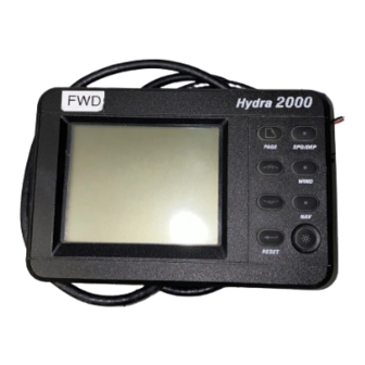
Part 2 - Operating Information PART 2 - OPERATING INFORMATION FULL FUNCTION DISPLAY (FFD) The HS 2000 System is operated by using the keys on any one of the NMEA or Standard Full Function Displays (FFD). Fig 2.1 - Full Function Display The information displayed on each FFD consists of a page of information comprising an upper display and a lower display. -
Page 17: On/Off Illumination Key
This key controls the application of power to the system and the level of illumination at all displays. One short press of this key applies power to the HS 2000 System and the display is activated. A second short press of the key provides full background illumination on all system displays. -
Page 18: Enter/Reset Key
HS 2000 User Manual Part 2 - Operating Information After a specific page has been selected, pressing the Scroll Up Key selects the upper display. Similarly, operation of the Scroll Down Key selects the lower display. 2.1.5 Enter/Reset Key The principle use of the Enter Key is to invoke selections chosen from the menu by the Scroll Keys. -
Page 19: Temperature (Temp) Key
Remote Push-Button (see Part 5 - Options). SUPER HALCYON 3 AND HALCYON 2000 COMPASS The Super Halcyon 3 and Halcyon 2000 Compasses are high performance electronic transmitting compasses which interface with your HS 2000 System. Heading and direction information can be HB-0846-03... -
Page 20: Examples Of Operation
These errors can be reduced to an insignificant level by following the Calibration procedure described in Part 3. EXAMPLES OF OPERATION The general principle of operating the HS 2000 System will be made clear by the following examples of function and page selection, and damping. -
Page 21: Page Display Configuration
HS 2000 User Manual Part 2 - Operating Information 2.4.2 Page Display Configuration To store the setting in Paragraph 2.5.1 as a permanent new page, proceed as follows: (1) Press Scroll Up or Scroll Down and scroll text until CNFG DSP is shown on the display. - Page 22 HS 2000 User Manual Part 2 - Operating Information Our second example is the entry of a damping value. To ascertain whether it is possible to damp a function, you should check the table in Paragraph 2.10 - Operating Functions.
-
Page 23: Examples Of Calibration
HS 2000 User Manual Part 2 - Operating Information EXAMPLES OF CALIBRATION The method of calibration of your HS 2000 System should be made clear by the following examples. The Calibration Process is described in detail in Part 3 - Calibration. -
Page 24: Alarms
HS 2000 User Manual Part 2 - Operating Information DATUM is referenced to the keel line, the value is negative, which is indicated by a minus sign before the left hand digit. (7) Press Enter to input the new DATUM value into the system. -
Page 25: Set Lo Alarm - Depth
HS 2000 User Manual Part 2 - Operating Information For example, when the SECTOR alarm is turned on, the alarm reference heading is the current compass heading. If the SECTOR alarm is set at 40°, the sector value is the compass heading +/- 20°. -
Page 26: Disable Alarms
TRIP FUNCTIONS The HS 2000 System provides two trip functions Trip Log and Dead Reckoning. The functions can be reset and restarted as required, for example, for keeping a separate log of elapsed distance for a given passage. -
Page 27: Lighting Control
LIGHTING CONTROL The level of illumination at system displays is controlled by the Power/Light Key. Use of this key normally controls all the HS 2000 System displays simultaneously. However, the level of illumination on a single FFD can be controlled individually using the menu choice - LOCAL LIGHTING. -
Page 28: Operating Notes
2.10 OPERATING FUNCTIONS The previous paragraphs have described how the HS 2000 System is constructed and how to use both the keys and basic menu structure. The following paragraphs describe each of the functions available in greater detail and how these features can best be applied within the boat. -
Page 29: Bearing To Waypoint
2000 System. It is used in many of the calculations of higher functions. The accurate calibration of the Paddle-Wheel or XTL Unit is essential. The HS 2000 System has a simple procedure for calibrating the underwater units which is described in Part 4 - Calibration. -
Page 30: Course Over Ground
HS 2000 User Manual Part 2 - Operating Information increased to smooth out the display value in rough conditions or conversely, reduced to accelerate the response in light conditions. 2.10.5 Course Over Ground Menu Heading: WAYPOINT Function Text: CRSE O/G... - Page 31 HS 2000 User Manual Part 2 - Operating Information Fig. 2.3 - Dead Reckoning HB-0846-03 2-18...
-
Page 32: Depth
HS 2000 User Manual Part 2 - Operating Information 2.10.7 Depth Menu Heading: DEPTH Function Text: DEPTH Update Rate: Once per second Units: Metres, feet and fathoms Note Audible, shallow/deep alarm available: Shallow range 0-99.9m Deep range unlimited Depth is one of the most important functions on the boat, being an essential navigational and safety tool. -
Page 33: Heading
HS 2000 User Manual Part 2 - Operating Information 2.10.9 Heading Menu Heading: NAVIGATE Function Text: HEADING Update Rate: Twice per second Units: Degrees magnetic Notes 1. Adjustable damping, 0-99 sec. 2. Sector alarm available. 3. Sensor alignment calibration. This is the compass heading, derived directly from the electronic Fluxgate Compass;... -
Page 34: 2.10.12 Sea Temperature
HS 2000 User Manual Part 2 - Operating Information 2.10.12 Sea Temperature Menu Heading: TEMP Function Text: SEA TEMP Update Rate: Once per second Units: Degrees Centigrade, Fahrenheit 1. Notes Requires temperature sensor. 2. Audible high/low alarm available. Knowledge of sea temperature is useful on long voyages when ocean currents are determined by changes in water temperature. -
Page 35: 2.10.15 Tidal Set And Drift
Your position fixer will either supply a true or magnetic bearing to the HS 2000 System. If it supplies true bearing then you must enter the magnetic variation into the HS 2000 System. It is found in the menu... -
Page 36: 2.10.17 Trip Log
HS 2000 User Manual Part 2 - Operating Information 2.10.16 Time to Waypoint Menu Heading: WAYPOINT Function Text: ETA WPT Update Rate: Provided by position fixer Units: Hours, minutes Notes 1. Also gives ETA. 2. Requires interfaced position fixing system. - Page 37 HS 2000 User Manual Part 3 - Calibration PART 3 - CALIBRATION CONTENTS Para Page INTRODUCTION BOAT SPEED/LOG CALIBRATION 3.2.1 Principle of Log Calibration 3.2.2 Preparation for Log Calibration 3.2.3 Calibration Runs 3.2.4 Log AUTO CAL Facility 3.2.5 Log AUTO CAL Procedure 3.2.6...
- Page 38 HS 2000 User Manual Part 3 - Calibration Intentionally Left Blank HB-0846-03...
-
Page 39: Introduction
PART 3 - CALIBRATION INTRODUCTION WARNING - Every care must be taken when undertaking any calibration procedure to ensure that the HS 2000 System is calibrated accurately and correctly. Incorrect calibration could lead to incorrect navigational information. Calibration of an integrated instrument system is one of the most misunderstood processes. -
Page 40: Calibration Runs
HS 2000 User Manual Part 3 - Calibration 3.2.3 Calibration Runs Consecutive runs at a constant speed should be made over a known distance. To eliminate the effect of tidal conditions, it is advisable to perform at least two runs, preferably three, along the measured track. -
Page 41: Log Auto Cal Procedure
HS 2000 User Manual Part 3 - Calibration 3.2.5 Log AUTO CAL Procedure Select BOAT SPD on the display. If BOAT SPD is in the upper display, press and hold Scroll Down to select CALBRATE. If BOAT SPD is in lower display, use Scroll Up to select CALBRATE. -
Page 42: Manual Calibration
Speed Calibration Referenced to a Known Value The following enhancement is only available when HS 2000 speed/depth computer is used in conjunction with an HS 2000 FFD Display with a software version later than 5C. To calibrate the boat speed with reference to a known value, for... -
Page 43: Compass Calibration
HS 2000 User Manual Part 3 - Calibration Press Enter, the lower text now shows CAL VAL 1 flashing. Press Scroll Down repeatedly, and the lower text will cycle through CAL1 VAL 1, CAL VAL 2, and CAL VAL 3 When CAL VAL 1 is displayed: Press Enter, the lower text shows SPD KTS. -
Page 44: Compass Heading Node Selection
3.3.2 Compass Heading Node Selection The HS 2000 System can accept heading data from a variety of different sources. These sources are known as Address Nodes and allow the system to identify which heading devices are connected to the system. The list below shows the various... -
Page 45: Super Halcyon 3 Compass Calibration Procedure
HS 2000 User Manual Part 3 - Calibration Press the Scroll Up key again until the display shows D/R CRSE ?M flashing. Press Enter. D/R CRSE ?M will now stop flashing. Press Scroll Down until the display shows CALBRATE. Press Enter 3 times. The display now shows HDG NODE and will display a value which flashes. -
Page 46: Halcyon 2000 Compass Calibration Procedure
HS 2000 under: NAVIGATE ? HEADING, CALBRATE ? CAL VAL1 For example, the compass was reading 320 degrees and it should read 316, then the value to enter would be -4. - Page 47 HS 2000 under: NAVIGATE ? HEADING, CALBRATE ? CAL VAL1 For example, the compass was reading 320 degrees and it should read 316, then the value to enter would be -4.
-
Page 48: Depth Calibration
DEPTH ? DEPTH, CALBRATE ? DATUM SEA TEMPERATURE CALIBRATION If a suitable temperature sensor is fitted, the HS 2000 System will monitor the current sea temperature; the paddle-wheel has a sensor incorporated within, in this case no further action is required. -
Page 49: Sea Temperature Offset Calibration
HS 2000 User Manual Part 3 - Calibration 3.5.1 Sea Temperature Offset Calibration To calibrate SEA TEMP C or SEA TEMP F proceed as follows: Select SEA TEMP C on upper half on FFD display. Press Scroll Down until the lower text shows CALIBRATE flashing. - Page 50 HS 2000 User Manual Part 4 - Installation Information PART 4 - INSTALLATION INFORMATION CONTENTS Para Page INTRODUCTION INSTALLATION DATA SHEETS HB-0846-03...
- Page 51 HS 2000 User Manual Part 4 - Installation Information Intentionally Left Blank HB-0846-03...
- Page 52 INTRODUCTION This part of the manual contains information relating to the interconnection of the units that make up the HS 2000 system. It is provided to enable qualified technicians to fault find or undertake the installation of additional units and thereby increase the number of functions available.
- Page 53 HS 2000 User Manual Part 4 - Installation Information INSTALLATION DATA SHEETS HB-0846-03...
- Page 54 HS 2000 User Manual Part 4 - Installation Information HB-0846-03...
- Page 55 HS 2000 User Manual Part 4 - Installation Information HB-0846-03...
- Page 56 HS 2000 User Manual Part 4 - Installation Information HB-0846-03...
- Page 57 HS 2000 User Manual Part 4 - Installation Information HB-0846-03...
- Page 58 HS 2000 User Manual Part 4 - Installation Information HB-0846-03...
- Page 59 HS 2000 User Manual Part 4 - Installation Information HB-0846-03 4-10...
- Page 60 HS 2000 User Manual Part 4 - Installation Information HB-0846-03 4-11...
- Page 61 HS 2000 User Manual Part 4 - Installation Information 8-BUTTON NMEA FULL FUNCTION DISPLAY INSTALLATION SHEET NMEA FFD FFD CABLE SYSTEM NMEA NMEA REMOTE CABLE FUNCTION COLOUR NETWORK INPUT OUTPUT BUTTON Network Data -ve Green Green Network Data +ve White...
- Page 62 Yellow Not used Brown INSTALLATION NOTES FOR HS 2000 ?? The system requires at least one FFD. ?? An FFD can be connected at any point on the system network. ?? Multiple FFD's can be used on the system network. Each can control and enter data into the system processor memory.
- Page 63 HS 2000 User Manual Part 4 - Installation Information HB-0846-03 4-14...
- Page 64 HS 2000 User Manual Part 5 - Options PART 5 - OPTIONS CONTENTS Para Page SYSTEM EXPANSION AUDIBLE ALARM 20/20 DISPLAY 5.3.1 The Display 5.3.2 Display Configuration 5.3.3 Function Selection - Remote Push-Button 5.3.4 Function Selection FFD 5.3.5 Re-configuring 20/20 Display HALCYON DISPLAY 5.4.1...
- Page 65 HS 2000 User Manual Part 5 - Options Intentionally Left Blank HB-0846-03...
-
Page 66: System Expansion
Part 5 - Options PART 5 - OPTIONS SYSTEM EXPANSION The HS 2000 System can be expanded to provide a wider range of facilities and features by the addition of further displays, sensors, and interfaces. These options are described in the following paragraphs. -
Page 67: Display Configuration
Display Configuration The 20/20 can be configured to display any function available on your HS 2000 System. It is, however, provided with 14 pre-set functions which may be selected by use of a Remote Push-Button connected to the display or via any FFD on the system. -
Page 68: Re-Configuring 20/20 Display
HS 2000 User Manual Part 5 - Options (2) Using the Scroll Down Key cycle through the 20/20 numbers and select the required Display Number. (3) Using the Scroll Up Key cycle through the 14 pre-set functions until the required function is displayed on the FFD. -
Page 69: Halcyon Display
HALCYON DISPLAY The Halcyon Display is a dedicated electronic compass display which may be connected to your HS 2000 System in a similar manner to an FFD. The display provides clear and accurate digital indication of compass heading information together with a bar graph indicating port and starboard off-course error relative to a set course. -
Page 70: The Keys
HS 2000 User Manual Part 5 - Options 5.4.1 The Keys The Halcyon Display is provided with the following five keys: Power/Lights Key Page Key Scroll Up Key Scroll Down Key Enter Key 5.4.2 Power/Lights Key The Power/Lights Key is operated in an identical manner to the Power/Lights Keys provided on the FFDs. -
Page 71: Off Course Function
HS 2000 User Manual Part 5 - Options (3) Press the Scroll Down key until the display shows POWER BOAT. (4) Press the Page key to exit the setup mode. The Halcyon Display has now been configured for Cruise Power operation. - Page 72 HS 2000 User Manual Part 5 - Options To select a specific course number proceed as follows: (1) Select the Stored Course Function by successive presses of the Page Key until the display shows the Stored Course Function. (2) Press Scroll Up and CRS 1 will flash.
- Page 73 HALCYON 2000 COMPASS The Halcyon 2000 Compass is a high performance electronic transmitting compass which interfaces directly with your HS 2000 System. Heading and direction information may be selected for display on any of the FFDs or on a Halcyon Display. In addition analogue compass card type displays may be added if your system has the optional Wind Board (402-10-005) PCB fitted.
- Page 74 HS 2000 User Manual Part 6 - Diagnostic Data PART 6 - DIAGNOSTIC DATA CONTENTS Para Page FFD DIAGNOSTICS 6.1.1 Diagnostic Function Selection 6.1.2 Key Test 6.1.3 Display 6.1.4 Network 6.1.5 6.1.6 PROM 6.1.7 EPROM 6.1.8 Lighting 6.1.9 Debug 6.1.10 RES-SYS 6.1.11...
- Page 75 HS 2000 User Manual Part 6 -Diagnostic Data Intentionally Left Blank HB-0846-03...
-
Page 76: Ffd Diagnostics
HS 2000 User Manual Part 6 - Diagnostic Data PART 6 - DIAGNOSTIC DATA FFD DIAGNOSTICS The FFD program contains a number of diagnostic functions which allow the FFD keys, display and memory to be tested, and also performs checks on other components of the system via the network. -
Page 77: Display
HS 2000 User Manual Part 6 -Diagnostic Data If the key operation is not detected after a short interval then the message TIME OUT is displayed. 6.1.3 Display The Scroll Up Key can be used to step the display through a sequence that switches ON single segments in all characters, blanks the display and switches ON all segments. -
Page 78: Lighting
6.1.9 Debug CAUTION: This test is not for normal use, since it may seriously affect the operation of the HS 2000 System. This option is used for accessing memory in other units in the system. 6.1.10 RES-SYS CAUTION: Do not use this option during normal operation as the system will give inaccurate results until re-calibrated. -
Page 79: Errors
Part 6 -Diagnostic Data 6.1.12 Errors This option is primarily used to interrogate the HS 2000 network and is designed for use by service technicians to ascertain levels of interference that may be present, for example, interference may be induced by an SSB transmitter or radar. The display shows the number of messages that have not been transmitted correctly in the first instance;... -
Page 80: Boat Stationary
HS 2000 User Manual Part 6 - Diagnostic Data All of these symptoms can be caused by external conditions, so care and additional tests should be performed before concluding that the fault lies with the Depth Sounder. Two Depth Sounder... -
Page 81: Boat Moving
HS 2000 User Manual Part 6 -Diagnostic Data 6.2.2 Boat Moving Symptom: Display shows: when boat is moving; this is most often an indication of difficult sounding conditions, but can also indicate a badly positioned transducer. Possible causes: (a) Difficult sounding conditions and/or Depth Sounder unable to track rapidly changing bottom. -
Page 82: Consistently Shows Shallow Depth
HS 2000 User Manual Part 6 - Diagnostic Data 6.2.3 Consistently Shows Shallow Depth Symptom: Display consistently shows a shallow depth between 0 and about 1.5m. Possible causes: (a) Faulty transducer. The transducer rings for too long after the transmit pulse is sent and the ringing is interpreted as a shallow return by the Depth Sounder. -
Page 83: Error Messages
HS 2000 User Manual Part 6 -Diagnostic Data will only occur when other boats are in the close vicinity, for example, when moored alongside in a crowded marina. Furthermore, acoustic noise can be generated by water flow past the transducer and other items of mechanical machinery. -
Page 84: Halcyon 2000 Compass
HS 2000 User Manual Part 6 - Diagnostic Data HALCYON 2000 COMPASS 6.4.1 Shows Heading and CAL Flashing Symptom: Display flashes a Heading and CAL Possible Causes: (a) The memory in the Halcyon 2000 is empty or has been corrupted. This may be due to a System Reset being performed or the first time the compass has been installed and not yet been calibrated. -
Page 85: Two Headings Flashing Alternately
HS 2000 User Manual Part 6 -Diagnostic Data 6.4.4 Two Headings Flashing Alternately Symptom: Pilot or Halcyon Displays shows 2 headings flashing alternately Possible Causes: (a) The Pilot has not been set to use the Halcyon 2000 as it’s heading source. See using Halcyon 2000 with a B&G ACP Pilot. -
Page 86: Nmea Alphabetical Index
1. Function repeated when no B&G fluxgate connected to system. Not used by HS 2000 autopilot. 2. Displayed when no B&G fluxgate connected to system. Can be used by HS 2000 autopilot. 3. Re-transmitted only. Not used by HS 2000. HB-0846-03 6-13... -
Page 87: Nmea Output Summary
HS 2000 User Manual Part 6 -Diagnostic Data 6.5.2 NMEA Output Summary Depth below transducer Geographic position, Latitude and Longitude Present heading, ?Magnetic Present heading, ?True Heading steering command Air temperature, ?Centigrade Sea temperature, ?Centigrade Surface wind direction and velocity... - Page 88 HS 2000 User Manual Appendix 1 HS 2000 CALIBRATION DATA A1.1 HS 2000 Settings Table Function Calibration Calibration Damping Alarm Alarm Type / Unit Value Value Value High Single BOAT SPD Hz/Knot STD LOG Datum High Offset DEPTH m, ft or fms...
Need help?
Do you have a question about the HS 2000 and is the answer not in the manual?
Questions and answers