B&G H5000 Operation Manual
Hide thumbs
Also See for H5000:
- Installation manual (66 pages) ,
- Advanced user information (18 pages) ,
- Quick reference manual (4 pages)
Table of Contents
Advertisement
Advertisement
Table of Contents

Related Manuals for B&G H5000


Summary of Contents for B&G H5000
- Page 1 H5000 Operation Manual ENGLISH www.bandg.com...
- Page 2 The H5000 system complies with the following regulations: • CE under EMC directive 2004/108/EC • Level 2 devices of the Radio communications (Electromagnetic Compatibility) standard 2008 The relevant Declaration of conformity is available in the H5000 section on the following website: www.bandg.com H5000 Operation Manual...
-
Page 3: Table Of Contents
Contents Introduction About this manual System overview H5000 components H5000 Central Processor Unit - CPU Webserver - Network portal Graphic display Race display HV Displays Analog displays Expansion modules Sensor modules Alarm module H5000 Pilot Controller System examples Hydra Hercules... - Page 4 Operating variables 113 Example data tables Polar table Boat speed / Heel correction True wind angle correction True Wind Speed correction Downwind correction angle for TWS 115 Maintenance Basic maintenance procedures Winter Storage / Laying Up Contents | H5000 Operation Manual...
-
Page 5: Introduction
Introduction About this manual This manual is a reference guide for operating the B&G H5000 instrument system. It assumes that all equipment is installed correctly, and that the system is ready to use. The manual assumes that the user has basic knowledge of navigation, nautical terminology and practices. - Page 6 Introduction | H5000 Operation Manual...
-
Page 7: System Overview
B&G’s web-browser interface lets you connect your PC or tablet to the network for setup, calibration and control of every part of your H5000 system. It utilizes a familiar web browser interface to allow quick calibration of instruments, easy setup of displays and confi guration of features. -
Page 8: H5000 Central Processor Unit - Cpu
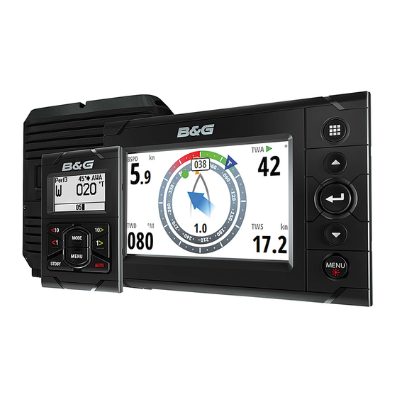
The browser-based confi guration of the H5000 system enables advanced calibration, set-up and diagnostics. Its web-style interface can be accessed via PC, tablet or smartphone. Graphic display The H5000 Graphic Display is a 5-inch, sunlight viewable, color display. It shows sailing data in digital or graphical form. System overview |... -
Page 9: Race Display
Race display The H5000 Race Display is a 7 segment display, 5-inch screen designed for viewing essential data at a glance. A dedicated page key allows quick switching between stored pages displaying 2 data values on each page alongside a unique bargraph providing immediate visual indication of performance targets, countdown timer status and more. -
Page 10: Analog Displays
The serial module has 2 COM ports, each with input & output. The modules support RS232, RS422, RS485 and NMEA 0183 devices. Modules can be located wherever is most convenient for the installer and can connect anywhere on the network. 10 | System overview | H5000 Operation Manual... -
Page 11: Sensor Modules
H5000 Pilot Computer The H5000 Pilot Computer links with the H5000 instrument system. The instrument system transmits sensor information over the network to the Pilot Computer. This information is processed by the Pilot Computer and sends signals to the drive system (linear ram, rotary drive or hydraulic pump) to steer the vessel on the desired heading/course. -
Page 12: H5000 Pilot Controller
H5000 Pilot Controller The H5000 Pilot Controller manages all autopilot functions as well as setup and commissioning. Use the H5000 Pilot Controller to select autopilot modes or manually steer the vessel. 12 | System overview | H5000 Operation Manual... -
Page 13: System Examples
System examples Hydra An example of a typical H5000 system. At the centre of the system is the H5000 Central Processor Unit (CPU). All sensor information is fed back to the CPU and can be easily controlled and confi gured via the Graphic display. -
Page 14: Hercules
Motion sensor Graphic display Alarm module Race display Central processor unit Analogue display Man Overboard Button - MOB Zeus series MFD H5000 Pilot Computer Zeus series MFD Webserver H5000 Pilot Controller Deckman Analog module Rudder reference unit Mast rotation sensor... -
Page 15: Performance
Race display Man Overboard Button - MOB Analogue display Analog module Zeus series MFD Analog module Zeus series MFD Analog device * H5000 Pilot Controller H5000 Pilot Computer Analog module Rudder reference unit Analog module Hydraulic ram Mast rotation sensor Webserver... -
Page 16: Autopilot Minimum System Requirement
12 Volt DC power supply Note: A system without an H5000 CPU will only provide data from the available sensors on the network and limited functionality. Only those menu options visible on the Graphic Display will be available to the user. -
Page 17: Operation
Alternative display palette for low light conditions. Night mode color Red, green, blue, white text color Note: Adjusting the backlight settings will eff ect all other displays in the same display group. See Network groups for more information. | 17 Operation | H5000 Operation Manual... -
Page 18: Default Graphic Display Pages
When navigating to a waypoint you can confi gure the Sail Steer page to show laylines to aid navigation. Tidal fl ow correction Tidal fl ow correction will calculate the tidal fl ow and off set the laylines accordingly. 18 | Operation | H5000 Operation Manual... - Page 19 When selected will show a dotted line indicating the minimum and maximum tack/gybe time period either side of the layline. This can be set to 5, 10, 15 & 30 minute increments. Speed / Depth Displayed data Description Description Speed Depth Acceleration bargraph | 19 Operation | H5000 Operation Manual...
- Page 20 Starboard end start line indicator Port end start line indicator Wind indicator (wind barb) Start line bias angle Start line - Arrow points to favored end Race timer Bias advantage (boat lengths) Distance to start line (perpendicular) 20 | Operation | H5000 Operation Manual...
- Page 21 Repeat steps 1 to 4 at the starboard end selecting ping starboard end as the bow touches the line The starboard end mark on the start line screen will go to solid green indicating it has been pinged | 21 Operation | H5000 Operation Manual...
- Page 22 DIST P: Distance to port end of start line BIAS: Start line bias angle Race timer DIST LINE: Distance to start line (perpendicular) DIST S: Distance to starboard end of start line BIAS ADV: Bias advantage (boat lengths) 22 | Operation | H5000 Operation Manual...
- Page 23 Waypoint bearing Estimated waypoint arrival time Course over ground Waypoint Off course limit (user setting) Course line Distance to waypoint Vessel indicator Cross track error XTE correction direction Left or Right Waypoint name | 23 Operation | H5000 Operation Manual...
- Page 24 Displayed data Description Description Set heading / Wind angle Heading indicator Compass scale Heading Performance level Set heading / Wind / Rudder angle Autopilot mode indicator Wind angle Rudder angle indicator Rudder angle 24 | Operation | H5000 Operation Manual...
-
Page 25: Data Page Transition
Highway (default) 1+3 digital* Tide (default) 1+6 digital* Autopilot (default) Centre analog* Satellites Analog +2* Weather Analog +3* Single time plot* Dual analog* Dual time plot* Note: * indicates, User confi gurable page | 25 Operation | H5000 Operation Manual... -
Page 26: Replacing A Data Page
Highlight the required page via the pages menu Press MENU Highlight Enabled Press the ENTER key to switch the page on or off . Note: A tick symbol next to the page denotes that the page is active. 26 | Operation | H5000 Operation Manual... -
Page 27: Menus
Use the UP/DOWN and ENTER keys to navigate through the menu options. Note: Whilst navigating a menu a single press of the PAGE key will return to the previous menu option. Example below: How to access the Time dialog via the Settings menu. MENU | 27 Operation | H5000 Operation Manual... -
Page 28: Race Timer
When a time is present in the start value fi eld the timer will begin to count down from that number when the timer is started. Once the time reaches zero it will begin counting up recording the elapsed time. 28 | Operation | H5000 Operation Manual... - Page 29 Auto start trip Selecting Auto trip start will enable the Trip Log to record your time and mileage from the moment the countdown timer begins counting up from zero. | 29 Operation | H5000 Operation Manual...
-
Page 30: Man Over Board
MOB waypoint data listed below. • If you have an H5000 CPU on the network the CPU will perform dead reckoning calculations to provide the estimated position of the man over board. This position will be displayed as a triangle symbol. -
Page 31: Hv Display Support
HV display support Any compatible B&G HV display e.g. 20/20 HV mast display connected to the network can be confi gured via the H5000 CPU webserver, Graphic Display or Race Display to show desired data e.g. speed, depth, wind speed. -
Page 32: Alarms
Press MENU on an alarm that requires parameters to be set will take you to the Enabled / Set limit menu. Select Set limit Set the required alarm parameter Press the PAGE key once you have fi nished editing Select OK to confi rm. 32 | Operation | H5000 Operation Manual... - Page 33 The alarm history can be accessed via the Alarm history menu. This stores alarm messages until they are manually cleared. Clear alarm history To clear the alarm history list, select ‘Clear All’ from the Alarm history menu. | 33 Operation | H5000 Operation Manual...
-
Page 34: Damping
Damping should not be confused with the update rate, which is the number of times per second that the function value is sent to the display. The update rate is fi xed for all the functions. 34 | Operation | H5000 Operation Manual... -
Page 35: Trip Log
Trip distance Trip time Average speed Maximum speed Note: Correctly calibrated boat speed is essential for accurate trip records. Shows total miles run from installation. This is based on distance over the water. | 35 Operation | H5000 Operation Manual... -
Page 36: Race Display
Alarm - Info Units of measure Controlling remote (HV) Displays Bargraph data type Autopilot engaged Bargraph data Active page number Page stored / Source select B&G H5000 CPU on the network Alarm - Critical 36 | Operation | H5000 Operation Manual... - Page 37 Using the UP and DOWN keys choose the required data type required, once selected press the ENTER key. The fi eld text will stop fl ashing and return to the data page. A long press of the PAGE key will save the display confi guration. | 37 Operation | H5000 Operation Manual...
- Page 38 Starts the timer. If a time value is preset the timer will countdown. If the timer is on zero it will count up. MENU Synchronize Synchronizing the timer will cause the timer to reset to the nearest whole minute. 38 | Operation | H5000 Operation Manual...
- Page 39 Set the lighting zone on the display. All units in the selected lighting zone will mirror each others light settings. Default setting is network. MENU Note: Press and hold the MENU / LIGHTS key to get to the Lighting menu. | 39 Operation | H5000 Operation Manual...
- Page 40 When alarms are set to ‘On’ the race display will show alarm messages when predefi ned alarm parameters on the network are triggered. When the race display alarm is set to off , no alarm message will be displayed on the race display. MENU 40 | Operation | H5000 Operation Manual...
-
Page 41: Diagnostics
Software version number. Check the B&G website for the current available software version. Description Description R = Indicates released version. Software version number Any other identifi cation is used for internal testing only | 41 Operation | H5000 Operation Manual... - Page 42 This is a visual test that needs to be performed by the user. Each segment will switch on in sequence until all segments are lit. It is the responsibility of the user to visually spot any faulty / missing LCD segments. Missing segment 42 | Operation | H5000 Operation Manual...
- Page 43 The display instance is a number that can be set as a reference for the user to distinguish between diff erent displays. By default the display instance is set to zero. Voltage Shows the current voltage supply to the display. | 43 Operation | H5000 Operation Manual...
-
Page 44: H5000 Pilot Controller
Rudder angle indicator Heading Keys The H5000 Pilot Controller is operated by 8 keys. These are used to operate the autopilot and adjust autopilot parameters. MODE Changes the autopilot mode / Scrolls up in menu options / Increases values. With active autopilot: Toggles between Wind mode and Auto mode 10º... -
Page 45: Autopilot Operation
MODE Scroll up MENU Scroll down Note: At anytime a single press of the STBY key will exit the menu and switch the autopilot to Standby mode! | 45 Operation | H5000 Operation Manual... -
Page 46: Autopilot Modes
Route information (MFD) to enter mode Steer the boat menu then select Non Follow manually using required mode the H5000 Pilot Controller Standby AUTO • Heading (True or Magnetic) • Set heading • Rudder angle •... - Page 47 Non Follow Up mode allows you to control the rudder position manually via the autopilot controller. Note: The autopliot will remain in Non Follow Up mode until it is disengaged by pressing the STBY key or a new mode is selected. | 47 Operation | H5000 Operation Manual...
- Page 48 The tacking/gybing operation will mirror the set wind angle on the opposite tack and a tack confi rmation window will appear on the display. To tack or gybe in wind mode press both 1° COURSE CONTROL keys on the H5000 Pilot Controller simultaneously. Hold them down until the confi rmation window appears. Press 1º...
-
Page 49: Sensor Calibration
Enter the Settings menu. Select depth via the calibration menu. Select Off set. MENU A dialog box will appear showing the current depth off set value. Note: The default value is zero | 49 Sensor calibration | H5000 Operation Manual... -
Page 50: Boat Speed
For accurate speed and log readings, it is essential that the paddlewheel is calibrated. Boat speed values can be shown in knots, kph or mph. Your preferred unit of measurement can be set in the units page of the setup menu. 50 | Sensor calibration | H5000 Operation Manual... - Page 51 Adjust the boat speed manually by selecting the Boat speed percentage slider. Adjust the percentage up or down as desired via the calibrate boat speed page. Confi rm the value. Select OK once complete. | 51 Sensor calibration | H5000 Operation Manual...
- Page 52 Start Run 1 Stop Run 1 Stop Run 2 Start Run 2 Start Run 3 End Calibration Note: It is important to maintain the same constant boat speed over each run. 52 | Sensor calibration | H5000 Operation Manual...
- Page 53 To enable dual sensors, see Dual sensor support / Measured sources for more information. Note: These options can be set via the H5000 Calibration menu on a compatible B&G Multi Function Display (MFD) Heel correction Edit the heel correction table to improve the accuracy of boat speed data when the boat is heeled over.
-
Page 54: Measured Sources
Follow the standard boat speed calibration procedure for each sensor Port & Starboard. Note: These options can be set via the H5000 Calibration menu on a compatible B&G Multi Function Display (MFD) Switching between boat speed sensors The CPU can handle sensor switching in a variety of diff... -
Page 55: Environment
Follow the standard wind sensor calibration procedure for each sensor. Note: These options can be set via the H5000 Calibration menu on a compatible B&G Multi Function Display (MFD) Switching between wind sensors The CPU handles sensor switching automatically. -
Page 56: Masthead Unit Adjustment
2 and enter this as a positive off set. MHU Align Once the off set has been calculated enter it into the MHU Align calibration fi eld 56 | Sensor calibration | H5000 Operation Manual... -
Page 57: Motion Correction
A 3D Motion sensor and mast height value is required in conjunction with a CPU running Hercules level software or greater to use this feature. TWA / TWS Correction tables The TWA and TWS Correction tables receive their information from the H5000 CPU. This information is not stored in the CPU. Note:... -
Page 58: Heading (Compass)
• On steel hulled vessels, the compass will need to be installed above decks away from the eff ects of the hull. 58 | Sensor calibration | H5000 Operation Manual... - Page 59 If heading data is not available from a compass sensor it is possible to use course over ground from a GPS. COG will be used in the true wind calculations. Note: The autopilot cannot be operated using COG as the heading source. COG cannot be calculated when stationary. | 59 Sensor calibration | H5000 Operation Manual...
-
Page 60: B&G Multi Function Display (Mfd
Find the polar fi le via the Files folder on the Tools page Copy the fi le from the portable media to the Polars directory The new Polar fi le will now be available via the Polars menu of the H5000 Calibration page Editing polar tables Open the table you wish to edit Select the number and adjust. -
Page 61: System Setup
Auto select can be performed via a Graphic Display, Webserver or one of the Zeus family of MFDs. Verify that all interfaced units are powered on Press the ENTER key to start the auto select procedure | 61 System setup | H5000 Operation Manual... - Page 62 Select the preferred data source. The selected source will be indicated by a tick in the check box. Device list Shows a list of all devices connected to the Network. Diagnostics Diagnostic data on the network. 62 | System setup | H5000 Operation Manual...
-
Page 63: Units
H5000 CPU info H5000 CPU software version and IP address. Note: IP address is required for Webserver login. Groups The group function is used to globally control parameter settings in groups of units. By assigning several units to the same group, a parameter update on one unit will have the same eff... -
Page 64: Decimal Places (Boat Speed And Sea Temperature)
From the time menu you can set the preferred time / date format and local time off set. Once complete select Save to save the settings and return to the settings menu. 64 | System setup | H5000 Operation Manual... -
Page 65: Simulate
The global reset will reset all settings in all displays along with performing a network reset removing all source selection. Note: After performing a global reset the Graphic Display will ask to do an auto source selection. | 65 System setup | H5000 Operation Manual... -
Page 66: About
About Shows the device information and software version currently installed on the display. Press the ENTER key to navigate back to the menu 66 | System setup | H5000 Operation Manual... -
Page 67: Autopilot Setup
Autopilot setup If an H5000 autopilot computer is connected to the network as per the instructions in the H5000 installation manual then the installation process can be performed via the H5000 Pilot Controller. Source selection A data source can be a sensor or a device connected to the network, providing information and commands to other networked devices. - Page 68 If rudder deadband is set to manual then you can make manual adjustments to the deadband value Rudder feedback Set the rudder feedback type. Note: It is important that you select the relevant rudder feedback unit via source selection. 68 | Autopilot setup | H5000 Operation Manual...
-
Page 69: Commissioning
Make sure the rudder feedback unit is installed and aligned as per it’s installation manual. The rudder calibration will set the correct relationship between the physical rudder movement and the rudder angle readout. Follow the rudder calibration procedure: | 69 Autopilot setup | H5000 Operation Manual... - Page 70 The Rudder test is verifi ed by the display showing ‘Success’. Press 1º RIGHT to return to the menu. Note: If Failed is given, check for correct electrical connection, check rudder feedback device has been confi gured correctly and or selected as the current source. 70 | Autopilot setup | H5000 Operation Manual...
- Page 71 After the Autotune process has been completed, ‘Finished’ will be shown on the screen and there should be no need for further adjustments. Fine tuning of these parameters are made by the response control. | 71 Autopilot setup | H5000 Operation Manual...
- Page 72 fi gures illustrate the eff ects of various Counter Rudder settings. New course Counter rudder setting too low = Overshoot response New course Counter rudder setting too high = Sluggish and creeping response New course Correct setting of counter rudder, ideal response 72 | Autopilot setup | H5000 Operation Manual...
-
Page 73: Response
Minimum gust in knots before gust compensation is applied. Response rate How aggressively the autopilot will react to gusts. TWA response Controls the size of the window in which gust response will operate. | 73 Autopilot setup | H5000 Operation Manual... - Page 74 Response rate Set the rate of heel compensation 1 to 10. 1 = slowest response, 10 = quickest response. 74 | Autopilot setup | H5000 Operation Manual...
-
Page 75: Steering
The autopilot is most sensitive to sudden course changes corrected. The autopilot is confi gured to the medium value when correcting sudden Medium course changes. Wide The autopilot is least sensitive to sudden course changes. | 75 Autopilot setup | H5000 Operation Manual... - Page 76 Entering a speed source in the manual fi eld will automatically make the autopilot use the manual speed source. Set the value back to zero to return to automatic speed source selection. Note: It is important that a close approximation of the vessel’s boatspeed is used. 76 | Autopilot setup | H5000 Operation Manual...
-
Page 77: Setup
Language Set the desired language Local • Reset the H5000 Pilot Controller settings without resetting the autopilot. This will return the H5000 Pilot Controller to its default sound and light settings • Advanced settings menu - Enable / Disable | 77... - Page 78 Key beeps Enable / disable H5000 Pilot Controller key beeps Software info • H5000 Pilot Controller serial number • Software version • Software release date 78 | Autopilot setup | H5000 Operation Manual...
-
Page 79: Webserver
Note: Before you can you use the B&G webserver you will need to connect your PC directly to the H5000 CPU via an ethernet cable or wirelessly via a WiFi-1 router. Direct via Ethernet Connect a computer directly to the H5000 CPU via an ethernet cable. - Page 80 Note: It will say “Websocket: Connected” in the top right-hand corner of the screen next to the help tab. If it says “Websocket: Not Connected” then check the H5000 CPU and router power and connections. Wireless via a WiFi-1 router Connect wireless devices to the H5000 CPU via a WiFi-1 router.
- Page 81 Connect a WiFi-1 to the H5000 CPU ethernet port via RJ45 converter cable Find the IP address of the H5000 CPU via a Graphic Display on the network. Note The H5000 CPU IP address can be found via the Graphic displays system, network menu under H5000 CPU info.
-
Page 82: Webserver Menus
Data Time Plots Live graphical data Race Timer Race timer control Trip Trip log data All Data All available data from H5000 CPU HV Displays Display List All HV Displays on network Calibration Depth Confi gure & setup Heading Confi gure & setup Boat Speed Confi... -
Page 83: Cpu Software Upgrade
Select ‘Unlock’ next to the CPU level your unlock code relates to Enter the unlock code in the dialog box Select ‘OK’ to complete Once the upgrade is complete reboot the CPU by cycling the power | 83 Webserver | H5000 Operation Manual... -
Page 84: Webserver Help Fi Les
Webserver help fi les Selecting the help tab located in the top righthand corner of the screen will show the help fi les related to the current page or feature. 84 | Webserver | H5000 Operation Manual... -
Page 85: Operating Variables
Operating variables This section details the operating functions within the H5000 system. The System Requirements sections advise of any additional requirements over a standard system. For this purpose a standard system is taken as being a Graphic display and CPU with Wind, Speed, Depth and Compass sensors. - Page 86 Analog Volts 1 Analog value 1 Analog Volts 2 Analog value 2 Note: Analog linear channel is the channel on the display where the data is sent to. There are user channels available. 86 | Operating variables | H5000 Operation Manual...
- Page 87 Trip Log was started. In simple terms this can be calculated as: Trip Log Average Speed Trip Time Variable name (default) Average Speed (AVS) Function name AVG SPD Units kt, mph, kph Alarms Calibration Damping | 87 Operating variables | H5000 Operation Manual...
- Page 88 This function repeats information received from a position fi xing device (e.g. GPS) via a NMEA input. Variable name (default) Bearing origin to destination Function name WPT BRG ºM, ºT Units Great Circle, Rhumb Line Alarms High, Low Calibration Damping 88 | Operating variables | H5000 Operation Manual...
- Page 89 High, Low Distance Reference, known distance SOG Reference, reference speed Hz/Kt, port and starboard and single Calibration Linearity correction Use SOG – Select SOG as alternative boat speed source. 0-9s Damping Dynamic Damping | 89 Operating variables | H5000 Operation Manual...
- Page 90 Variable name (default) Boom Position (Boom) Function name BOOM POS Units Arbitrary Alarms Position 1 (known value 1) Volts 1 (automatically recorded) Calibration Position 2 (known value 2) Volts 2 (automatically recorded) Damping 90 | Operating variables | H5000 Operation Manual...
-
Page 91: Course Over Ground
Course Over Ground (COG) displays the current course of the yacht relative to land (rather than the water), referenced to North. Variable name (default) Course Over Ground (COG) Function name Units ºM, ºT Alarms Calibration Damping 0-9s | 91 Operating variables | H5000 Operation Manual... - Page 92 Variable name (default) Daggerboard (Dag) Function name DAGGER Units As set by calibration Alarms Position 1 (known value 1) Volts 1 (automatically recorded) Calibration Position 2 (known value 2) Volts 2 (automatically recorded) Damping 92 | Operating variables | H5000 Operation Manual...
- Page 93 D/R calculations are based on the Course function, therefore if a Heel Angle sensor is fi tted the D/R data can be corrected for Leeway. System requirements Connection Variable name (default) D/RCourse, D/RDistance DRD/DRC Function name DR BRG and DR DIST Units ºM, ºT, nm Alarms Calibration Damping | 93 Operating variables | H5000 Operation Manual...
- Page 94 Alarms Calibration Damping Ground wind - Speed Wind speed relative to the ground at a fi xed position. Variable name (default) Ground wind speed Function name Units kt, m/s Alarms Calibration Damping 94 | Operating variables | H5000 Operation Manual...
- Page 95 Hercules systems to correct wind data for the change of orientation of the sensor in the airfl ow. Variable name (default) Heel Function name HEEL Units Degrees Alarms Calibration Off set Damping 0-9s | 95 Operating variables | H5000 Operation Manual...
- Page 96 An P or S is shown in the left hand digits to signify Port or Starboard laylines respectively Note: The Race display doesn’t show the P or S Variable name (default) Layline Distance (dLL) Function name LL DIST Units Alarms Calibration Damping 96 | Operating variables | H5000 Operation Manual...
- Page 97 Displays local time from an interfaced position fi xer. Ensure that your position fi xer is confi gured to apply the correct local time off set. Note: Not available on Race Display Variable name (default) Local Time (Time) Function name TIME LOC Units Alarms Calibration Damping | 97 Operating variables | H5000 Operation Manual...
- Page 98 True Wind and Apparent Wind. Variable name (default) Measured Wind Speed (MWS) Function name Units Alarms Calibration Damping 98 | Operating variables | H5000 Operation Manual...
- Page 99 Boat Speed is given and hence the Apparent Wind Speed and Angle can be calculated. Should the leg be upwind or downwind, rather than free, the H5000 calculates the data using the Target TWA on the favoured tack, this situation is indicated on the display by the position of a small bar at the top (upwind) or bottom (downwind) of the digits.
- Page 100 Polar Performance % function in terms of Boat Speed as a percentage of Polar Boat Speed. Variable name (default) Polar Speed (POL) Function name POL SPD Units Alarms Calibration Damping 100 | Operating variables | H5000 Operation Manual...
- Page 101 The Remote functions are declared (in the External menu) by the Performance software and are used to display data from an external system (e.g. a PC running B&G Deckman) via the H-Link protocol. | 101 Operating variables | H5000 Operation Manual...
- Page 102 The Stored Log runs continually and records the total distance travelled by the yacht since the system was initially commissioned. Variable name (default) Stored Log (Log) Function name STD LOG Units Alarms Calibration Damping 102 | Operating variables | H5000 Operation Manual...
- Page 103 Temperature - Aux Displays the current temperature read via the sensor. Variable name (default) Aux Temperature (AUX) Function name AUX TEMP Units ºC, ºF Alarms High and Low Calibration Off set Damping | 103 Operating variables | H5000 Operation Manual...
- Page 104 If your position fi xer sends magnetic bearing, check that the variation is correctly entered (or calculated) in the position fi xer. Variable name (default) Timer Function name TIMER Units hh:mm:ss Alarms Countdown bleep via Audible Alarm Calibration Set countdown period Damping 104 | Operating variables | H5000 Operation Manual...
- Page 105 Units Alarms Calibration Damping Trim (Fore/Aft) The Trim function displays the fore/aft trim angle of the yacht. Variable name (default) Trim Function name TRIM Units Degrees Alarms Calibration Off set Damping 0-9s | 105 Operating variables | H5000 Operation Manual...
- Page 106 Variable name (default) Trim Tab (Tab) Function name TRIM TAB Units Degrees Alarms Position 1 (known value 1) Volts 1 (automatically recorded) Calibration Position 2 (known value 2) Volts 2 (automatically recorded) Damping 106 | Operating variables | H5000 Operation Manual...
- Page 107 Apparent Wind Speed Heading Apparent Wind Angle Wind Variable name (default) True Wind Angle (TWA) Function name Units Degrees Alarms Sector True Wind Correction Tables Calibration AutoCal TWA correction routine Damping 0-9s | 107 Operating variables | H5000 Operation Manual...
- Page 108 True Wind Speed (TWS) is the speed of the wind measured relative to the water surface. Variable name (default) True Wind Speed (TWS) Function name Units kt, m/s Alarms High, Low Calibration True Wind Correction Tables Damping 0-9s 108 | Operating variables | H5000 Operation Manual...
- Page 109 True wind direction Boat speed True Wind Angle VMG Upwind True wind direction True Wind Angle Boat speed VMG Downwind Variable name (default) Velocity Made Good (VMG) Function name Units Alarms Calibration Damping 0-9s | 109 Operating variables | H5000 Operation Manual...
- Page 110 fi xer. Optimum VMG to Mark Description True wind direction Direction of new mark Optimum VMC course Polar curve Variable name (default) VMG Waypoint (VMC) Function name VMG CSE Units Alarms Calibration Damping 110 | Operating variables | H5000 Operation Manual...
- Page 111 True Wind Speed. Polar tables can be derived either by theoretical predictions, e.g. measurement certifi cates, or by analyzing the boat’s actual performance via software such as Deckman. The H5000 has one polar table stored in its memory.
- Page 112 Yaw rate is displayed on the system for diagnostic purposes only. It is also used internally by the autopilot. Variable name (default) Yaw Rate (Yaw) Function name YAW RATE Units Degrees Alarms Calibration Damping 112 | Operating variables | H5000 Operation Manual...
-
Page 113: Example Data Tables
Example data tables Polar table True Wind Speed | 113 Example data tables | H5000 Operation Manual... -
Page 114: Boat Speed / Heel Correction
-2.0 -1.0 165º TWA -1.0 -1.0 -2.0 True Wind Speed correction Column TWS > Correction -0.6 -1.2 -1.8 -2.4 -3.0 -3.6 Downwind correction angle for TWS Column TWS > Down angle 114 | Example data tables | H5000 Operation Manual... -
Page 115: Maintenance
fi ne grade wet/dry paper. Inspect the o-rings on both the sensor and the blanking plug and replace if necessary, and then lubricate with silicone lubricant or petroleum jelly (Vaseline®). | 115 Maintenance | H5000 Operation Manual... -
Page 116: Winter Storage / Laying Up
If the mast is un-stepped, care must be taken to ensure that the cable is not cut through, but disconnected at the junction box below decks. The bare ends of the cable should be smeared with silicone grease. 116 | Maintenance | H5000 Operation Manual... - Page 117 www.bandg.com...
Need help?
Do you have a question about the H5000 and is the answer not in the manual?
Questions and answers