Table of Contents
Advertisement
CONTENTS
CONTENTS ..................................................................... 1
GENERAL INTRODUCTION TO B&G NETWORK ......... 2
INTRODUCTION TO NETWORK QUAD......................... 3
EXAMPLE SYSTEMS USING NETWORK QUAD........... 4
SELECTING THE DISPLAY MODE ................................ 5
USING THE SPEED KEY................................................ 6
CALIBRATION AND OPERATING PARAMETERS ........ 7
SETTING THE DISPLAY DAMPING ............................... 8
SETTING THE SPEED AND LOG UNITS ....................... 9
SPEED AND LOG CALIBRATION ................................ 10
1 - MANUAL CALIBRATION - CAL................................ 11
2 - MANUAL CALIBRATION - LOG CAL ....................... 12
3 - AUTOMATIC CALIBRATION - AUTO CAL ............... 13
RESETTING THE DEAD RECKONED DISTANCE ....... 15
USING THE DEPTH KEY.............................................. 16
THE DEPTH DATUM - CAL........................................... 17
SETTING THE DEPTH DATUM .................................... 18
SETTING THE DEPTH UNITS ...................................... 19
DEPTH ALARMS .......................................................... 20
ENABLING/DISABLING THE SHALLOW ALARM ......... 21
ADJUSTING THE SHALLOW ALARM VALUE .............. 21
610-HB-0503-05
DEEP ALARM
ENABLING/DISABLING THE DEEP ALARM .................22
ADJUSTING THE DEEP ALARM VALUE ......................22
ANCHOR ALARM
USING THE ANCHOR ALARM ......................................23
ENABLING/DISABLING THE ANCHOR ALARM ...........24
ADJUSTING THE ANCHOR ALARM DEEP LIMIT.........25
USING THE TIMER/TEMP KEY ....................................26
RESETTING THE TRIP LOG .........................................27
SETTING THE TIMERS AND LAP TIMER .....................28
SETTING THE TEMPERATURE UNITS ........................29
CALIBRATING THE TEMPERATURE SENSOR............30
USING THE LIGHTS KEY .............................................31
NETWORK ALARMS.....................................................32
FAULT AND ERROR MESSAGES.................................33
INSTALLATION .............................................................34
SITING THE UNIT..........................................................34
MOUNTING THE UNIT ..................................................34
SPECIFICATION............................................................36
1
Advertisement
Table of Contents

Related Manuals for B&G Network Series


Summary of Contents for B&G Network Series
-
Page 1: Table Of Contents
CONTENTS CONTENTS ..............1 DEEP ALARM GENERAL INTRODUCTION TO B&G NETWORK ..2 ENABLING/DISABLING THE DEEP ALARM ....22 ADJUSTING THE DEEP ALARM VALUE ......22 INTRODUCTION TO NETWORK QUAD......3 ANCHOR ALARM EXAMPLE SYSTEMS USING NETWORK QUAD... 4 USING THE ANCHOR ALARM ........23 SELECTING THE DISPLAY MODE ........ -
Page 2: General Introduction To B&G Network
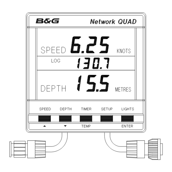
INTRODUCTION TO NETWORK QUAD GENERAL INTRODUCTION TO B&G NETWORK The Network QUAD unit measures and displays Speed, The B&G Network range of instruments is designed to be Depth, Log, Timer and Sea Temperature information on a used as individual units or connected together to form an large back-lit Liquid Crystal Display (LCD). -
Page 3: Introduction To Network Quad
NETWORK QUAD DISPLAY UNIT INTRODUCTION TO NETWORK QUAD CONT'D The Network QUAD unit has three adjustable alarms: 1. Shallow water alarm 2. Deep water alarm 3. Anchor alarm An internal alarm buzzer will sound when an alarm condition is met and the display will flash. The alarm is broadcast to all other Network Instruments in an integrated system, they will also sound their alarms and flash their displays (except Network WIND and Network TACK). -
Page 4: Example Systems Using Network Quad
EXAMPLES SYSTEMS USING NETWORK QUAD Only one Network QUAD unit should have speed and depth sensors connected to it and set to transducer mode. Up to three more Network QUAD (set to repeater mode) or QUAD REPEATER units can be connected on to the system network. -
Page 5: Selecting The Display Mode
SELECTING THE DISPLAY MODE The Network QUAD unit has two operating modes. The correct mode must be selected for your Network system to operate properly. tYPEt Transducer mode, the unit uses and displays speed and depth data from sensors connected directly into the display unit. tYPEr Repeater mode, the unit operates as a repeater using data from the system network. -
Page 6: Using The Speed Key
USING THE SPEED KEY Boat speed information is permanently displayed in the top area of the LCD. Press the SPEED key to cycle through the following options: SPEED Current boat speed in Knots, can also be displayed in MPH. Average boat speed since the last reset of AVERAGE SPEED the trip log. -
Page 7: Calibration And Operating Parameters
CALIBRATION AND OPERATING PARAMETERS When current boat speed is displayed, press the SETUP key to cycle through the following options: DAMPING The response time of the display to changes in boat speed. SPEED KNOT The boat speed can be displayed in Knots or MPH. -
Page 8: Setting The Display Damping
SETTING THE DISPLAY DAMPING Damping allows the response time of the displayed speed value to be slowed down if it is to jumpy in rough weather, or to sped it up when the conditions are calm. The damping works by averaging the values over a set time period; the longer the time period the smoother the readings, however the longer it takes to see a change. -
Page 9: Setting The Speed And Log Units
SETTING THE SPEED AND LOG UNITS The Network QUAD can be set to display boat speed in Knots or MPH. If boat speed is in Knots then log is in Nautical Miles. If boat speed is in MPH then log is in Statute Miles. Use ! or "... -
Page 10: Speed And Log Calibration
SPEED AND LOG CALIBRATION Before Network QUAD is used for navigation the boat speed and log have to be calibrated to ensure accuracy for your installation and the boats hull characteristics. Three methods are available with the Network QUAD unit, two manual adjustments and one automatic: MANUAL CALIBRATION 1. -
Page 11: Manual Calibration - Cal
METHOD 1. - MANUAL CALIBRATION - CAL This procedure requires a reference boat speed with which to IMPORTANT NOTE: This method of calibration must not be compare the Network QUAD units displayed boat speed. For carried out at boat speeds of LESS THAN 3 KNOTS as example, another boat with an accurate inaccurate values can be entered into the units memory. -
Page 12: Manual Calibration - Log Cal
METHOD 2. - MANUAL CALIBRATION - LOG CAL If the log or boat speed is in error by a known percentage then this method allows the calibration figure or LOG CAL to be adjusted by that amount. The calibration figure is measured in Hertz per knot (Hz/kt), the factory set value is 6.25. -
Page 13: Automatic Calibration - Auto Cal
METHOD 3. - AUTOMATIC CALIBRATION - AUTO CAL This procedure will automatically and accurately calibrate • Press the ENTER key when in line with marker A, to start the boat speed and log and is the recommended method for run 1. The display will flash AUTO CAL 1. Press ENTER most boats. - Page 14 AUTOMATIC CALIBRATION PROCEDURE Distance measured on a chart Start Stop Run 1 Run 1 Start Stop Run 2 Run 2 Start Stop Run 3 Run 3 ABORTING AUTO CAL...
-
Page 15: Resetting The Dead Reckoned Distance
RESETTING THE DEAD RECKONED DISTANCE This facility allows the Dead Reckoned (DR) distance log to be reset. The Network QUAD unit cannot display the DR information, however Network SPEED and Network DATA both display it. Press SPEED key to Press SETUP key 6 times Press ENTER key, there The dr log will be reset to display the current boat... -
Page 16: Using The Depth Key
USING THE DEPTH KEY The current water depth is permanently displayed in the bottom LCD area in metres, feet or fathoms. The unit is factory set to metres. The depth displayed is from the depth datum, see DEPTH DATUM. Press the DEPTH key to cycle through the following options: The Depth Datum can be adjusted so the displayed water depth is from the water-... -
Page 17: The Depth Datum - Cal
THE DEPTH DATUM - CAL The depth datum CAL is an offset calibration value used to determine the displayed information reference point. It is added to the actual measured water depth to display the depth from the waterline, the depth sensor (transducer) or the keel/outdrive depth. -
Page 18: Setting The Depth Datum
SETTING THE DEPTH DATUM CAL zero, depth from transducer. CAL positive, depth from waterline. CAL negative, depth from keel. NOTE: If the CAL LOCK is set then the CAL value cannot be changed. Consult your B&G dealer for advise. Use ! or " to Press DEPTH key Press SETUP key Press ENTER to... -
Page 19: Setting The Depth Units
SETTING THE DEPTH UNITS The Network QUAD unit can be set to display depth in Metres, Feet or Fathoms. The selected units are used for displayed depth information on all Network instruments on the entire Network system. Use ! or " to Press DEPTH Press SETUP key Press ENTER... -
Page 20: Depth Alarms
DEPTH ALARMS The display will show OFF if the alarm is disabled or the Deep alarm. alarm value when enabled. The value will be displayed in Factory set to 10.0m, (32.8ft, 5.4 fathoms). metres, feet or fathoms depending on the selected depth Adjustable range 0 - 180m, 0 - 590 ft, 0 - 98.4 fa. -
Page 21: Enabling/Disabling The Shallow Alarm
ENABLING/DISABLING THE SHALLOW ALARM Use ! or " to Press DEPTH key Press SETUP key, Press ENTER key, Press ENTER to Press DEPTH key, to display the the alarm state will the alarm state enable/disable the memorise the the current value shallow alarm. -
Page 22: Enabling/Disabling The Deep Alarm
ENABLING/DISABLING THE DEEP ALARM Use ! or " to Press DEPTH key Press SETUP key, Press ENTER key, Press ENTER to Press DEPTH key, to display the deep the alarm state will the alarm state enable/disable the memorise the the current value is alarm. -
Page 23: Using The Anchor Alarm
USING THE ANCHOR ALARM The Anchor Alarm uses two adjustable alarm limits. The The anchor alarm depth limits are shown alternatively when alarm will sound if the water is deeper or shallower, by the they are enabled and displayed using the DEPTH key. set values, than the original depth of water when the alarm was enabled. -
Page 24: Enabling/Disabling The Anchor Alarm
ENABLING/DISABLING THE ANCHOR ALARM Use ! or " to Press SETUP Press ENTER Press ENTER to Press DEPTH key Press DEPTH key enable or disable key, to display key, the alarm memorise the to display the to display the alarm. alarm state. -
Page 25: Adjusting The Anchor Alarm Shallow Limit.25
ADJUSTING THE ANCHOR ALARM SHALLOW LIMIT Use ! or " to Press DEPTH key Press SETUP key Press ENTER key, Press ENTER to Press DEPTH key change the value. to display the twice to display the the value display memorise the new to display anchor alarm. -
Page 26: Using The Timer/Temp Key
USING THE TIMER/TEMP KEY Press the TIMER/TEMP key to cycle through the options: SEA TEMPERATURE The Sea Temperature is displayed in °C Celsius or °F Fahrenheit. TRIP LOG A reset log that can be displayed in Nautical miles or Statute Miles. This is determined by the selection of the displayed speed units (see SETTING THE SPEED AND LOG UNITS). -
Page 27: Resetting The Trip Log
RESETTING THE TRIP LOG The Trip Log is reset to zero and starts again as soon as the ENTER key is pressed. Press TIMER key to Press SETUP key, Press ENTER key, the Press TIMER key to display the TRIP LOG. Display flashes. -
Page 28: Setting The Timers And Lap Timer
SETTING THE TIMERS AND LAP TIMER The Lap Timer can be used to `freeze' the displayed time with any of the three Timers. Press SETUP key Press the TIMER Press ENTER Press TIMER Press TIMER key Press TIMER key key to display the 10 min. -
Page 29: Setting The Temperature Units
SETTING THE TEMPERATURE UNITS The sea temperature can be displayed in Celsius or Fahrenheit. Use ! or " keys Press TEMP key Press SETUP key Press ENTER if Press ENTER Press TEMP key until the sea once to display the units are to be to change the key to memorise to display sea... -
Page 30: Calibrating The Temperature Sensor
CALIBRATING THE TEMPERATURE SENSOR Temperature calibration should only be carried out when the built-in sea water temperature sensor (part of the speed sensor) is considered to be inaccurate. The temperature of the water will have to be measured with an accurate temperature sensing device, this value can then be entered into the Network QUAD unit. -
Page 31: Using The Lights Key
USING THE LIGHTS KEY The Network QUAD Display unit has 3 levels of illumination and off, controlled by the LIGHTS key. It also changes the illumination level of the key legends. The LIGHTS key is always illuminated so even in complete darkness the key can be located. -
Page 32: Network Alarms
NETWORK ALARMS The Network QUAD unit has an internal buzzer that will NETWORK PILOT ALARM DISPLAYS (NOT QUAD UNIT) sound when an alarm condition is met on a Network unit that has alarm functions ie. Network DEPTH and Network The Watch Alarm is a count-down timer with is activated QUAD for depth alarms and Network PILOT for Watch at the end of the preset count-down period. -
Page 33: Fault And Error Messages
FAULT AND ERROR MESSAGES NETWORK PILOT FAULT DISPLAY (NOT QUAD UNIT) UNIT INTERNAL ERRORS If Network PILOT should have a fault the autopilot computer In the unlikely event that your Network QUAD unit should unit will send a message to all other Network Display Units. develop an internal error, the unit will sound it's alarm The Network units will alternately display the follow continuously and the display will show an error number. -
Page 34: Installation
MOUNTING THE UNIT INSTALLATION Use the cutting template supplied to mark the centres of the The display heads are supplied with a clip-in mounting holes for the self-tapping screw, the fixing stud holes and bracket which allows for easy installation, access from the mounting bracket. - Page 35 INSTALLATION DATA 110.0mm 25.0mm 65.0mm Network QUAD Locking stud fixing Speed sensor connector 110.0mm Depth sensor connector SPEED DEPTH TIMER SETUP LIGHTS TEMP ENTER Network connector Network & Power connector Mounting bracket Rubber Gasket 82.0mm Sun-cover Display Unit Gasket Fit the gasket around the mounting bracket 70.0mm hole Bulkhead...
-
Page 36: Specification
SPECIFICATION PHYSICAL PARAMETERS ELECTRICAL Construction High impact ABS plastic Power Supply 12V DC nominal (10 to 16V) Window Acrylic Operating Current 40mA typical, 100mA illuminated Display Back-lit Liquid Crystal Display: Protection Connect via external fuse or circuit Large Digits: 15mm 0.6" breaker.
Need help?
Do you have a question about the Network Series and is the answer not in the manual?
Questions and answers
Showing a rudder error. How to reset?
To reset a rudder error on a B&G Network Series device, switch off the instruments at the power supply, wait a few moments, and then switch them on again. If the fault remains, record the error number, switch off the supply, disconnect the faulty unit, and return it with the error number for servicing.
This answer is automatically generated
Can I download a manual without installing a brouser?