B&G h3000 User Manual
Hide thumbs
Also See for h3000:
- Pilot's handbook manual (120 pages) ,
- System installation manual (56 pages)
Table of Contents
Advertisement
Advertisement
Chapters
Table of Contents

Related Manuals for B&G h3000


Summary of Contents for B&G h3000
- Page 1 www.bandgservice.co.uk...
-
Page 3: Table Of Contents
Notifi cation ......................8 Liability and Safety Warnings ................9 About B&G ..................... 10 About this Handbook ..................10 SYSTEM INTRODUCTION H3000 System Example .................. 12 PROCESSORS Central Processing Unit (CPU) ............... 13 Expansion Processor ..................15 Halcyon Gyro Processor .................. 15 DISPLAYS Graphical Function Display (GFD) .............. - Page 4 H3000 Instrument Handbook GFD MENU STRUCTURE Function Menu ....................31 GFD MAIN MENU Timer ....................... 34 GPS........................34 Pilot ......................... 35 Trip Control ..................... 37 Remote Units ....................38 SETUP Alarms ......................39 Calibration ....................... 41 Damping ......................41 Dynamic Damping ..................42 This Display ....................
- Page 5 H3000 Instrument Handbook Boat Speed ....................... 98 Boom Position ....................99 Canard Angle ....................100 Course......................101 Course Over Ground ..................102 Cross Track Error (XTE) ................102 Course To Steer ..................... 103 Daggerboard ....................104 Dead Reckoning .................... 105 Depth ......................
- Page 6 VMG......................149 VMG Performance ..................151 Wind Angle to Mast ..................153 Yaw Rate ....................... 154 INSTALLATION INFORMATION H3000 System Example ................156 Network Installation ..................157 GFD Installation .................... 159 Analogue Installation ..................161 HV Display Installation ................. 162 Remote Button....................
- Page 7 Example Polar Table ..................213 DIAGNOSTICS System Diagnostics and Troubleshooting ............. 221 GFD Diagnostics ................... 221 The Fastnet Databus ..................225 H3000 CPU ....................226 Masthead Unit (Wind Sensor) ............... 227 Depth Sensor ....................228 Halcyon 2000 Compass ................. 233 ROUTINE MAINTENANCE General Maintenance ..................
-
Page 8: B&G
H3000 Instrument Handbook B&G NOTIFICATION The information contained in this document is subject to change without prior notice. Navico Holding shall not be liable for errors contained herein or for incidental or consequential damages in connection with the furnishing, performance or use of this document. -
Page 9: Liability And Safety Warnings
Warning: Operational Hazard The H3000 system is an Electronic Navigation aid and is designed to assist in the navigation of your yacht. It is not designed to totally replace conventional navigation procedures and precautions and all necessary precautions should be taken to ensure that the yacht is not placed into danger. -
Page 10: About B&G
Instructions in this handbook describe the controls and calibration of your H3000 system. You can also use the controls on the RemoteVision. The H3000 Central Processing Unit is the core of the system and has Hydra, Hercules, Hercules Performance and Motion level software all in one box. -
Page 11: System Introduction
H3000 Instrument Handbook SYSTEM INTRODUCTION H3000 is the successor to the leading Hydra 2000 and Hercules 2000 instrument and Pilot systems from B&G. Hydra and Hercules 2000 and its predecessors have been used and depended upon by the world’s serious cruising and racing fraternity for fi fty years, during which time the systems have been constantly evolving to provide the most dependable instrument and autopilot systems available. -
Page 12: H3000 System Example
H3000 Instrument Handbook H3000 SYSTEM EXAMPLE Above is an example of a typical H3000 system. At the centre of the system is the Central Processor Unit (CPU). All sensor information is fed back to the CPU and can be easily controlled and confi... -
Page 13: Processors
PROCESSORS CENTRAL PROCESSING UNIT (CPU) The CPU is the core of the H3000 system, taking the majority of sensor inputs and using a dedicated processor to rapidly calculate and calibrate further functions and distribute them to display units and external devices. - Page 14 Secondary Pulse input for additional boat speed sensor Boat speed linearity/heel angle correction Hercules Performance Designed to further enhance the H3000 range, the Hercules Performance level software integrates B&G’s Tactical Navigation software, Deckman, along with several advanced features: Deckman™ Tactical Navigation software H-Link™...
-
Page 15: Expansion Processor
The Halcyon Gyro Processor can also be used as an interface to output NMEA heading and AD10 from a B&G system compass, or to accept NMEA heading information from an external compass for use on the H3000 system. HB-3000-05... -
Page 16: Displays
The GFD has a simple easy to learn key confi guration that gives the user the confi dence to set-up and confi gure the H3000 system hassle free. As well as shortcut navigation keys to display important data at the touch of a key, all data can be reviewed and displayed in a variety of on screen confi... -
Page 17: Hv Displays
H3000 Instrument Handbook HV DISPLAYS The HVision range of displays are lightweight, single-line data units incorporating B&G’s unique HV technology. HV technology ensures the maximum contrast, perfect backlighting and no possibility of condensation. HV displays are the clearest displays available. -
Page 18: Apparent Wind Angle
H3000 Instrument Handbook 30/30 The 30/30 is designed as a mast display for yachts in the range 60-90’ (18-27m) LOA. Providing these larger yachts with the perfect size of display. The 30/30 is also the ideal display for deck or bridge displays on super yachts. -
Page 19: Analogue Indicators
H3000 Instrument Handbook Remote Button If a Remote Button is connected to an HV Display any one of the 14 pre-set functions may be selected by pressing and holding down the button. The Display will then cycle through the functions. When the required function is displayed, release the button. -
Page 20: Remotevision
Rudder REMOTEVISION The RemoteVision is a wireless link to your H3000 system, as well as a Pilot control, all in the palm of your hand. The lightweight, palm sized unit is linked to the instruments and pilot through a small wireless port and using a secure wireless connection, which is suitable for use on both small and large vessels. -
Page 21: Sensors
To enable regular cleaning of the paddle wheel, the housing is provided with a self- closing valve, which closes automatically when the sensor is retracted. The H3000 CPU can be confi gured to monitor two paddle wheel sensors simultaneously. DEPTH SENSOR This unit can be either a removable through hull unit, or moulded in hull for reduced drag. -
Page 22: Halcyon Gyro-Stabilised Compass
It also provides high accuracy Heel and Trim data. The Halcyon Gyro-Stabilised Compass interfaces to the H3000 system via the Halcyon Gyro Processor that transmits this information to the B&G Fastnet network, or via direct connection to the B&G Pilot ACP unit. -
Page 23: Clinometer - Trim Angle Sensor
H3000 Instrument Handbook CLINOMETER – TRIM ANGLE SENSOR Provides display of Trim Angle and increases the accuracy of the following functions: Apparent Wind Angle Apparent Wind Speed True Wind Angle True Wind Speed True Wind Direction MAST ROTATION SENSOR This is essential if your mast rotates, otherwise the wind data will become inaccurate as the mast rotates away from the centreline. -
Page 24: Motion Sensor
Measures rig loads, typically used on forestay, vang, outhaul, runners, backstay, and mainsheet. Up to 12 B&G loadcells can be added to the H3000 system via the Fastnet databus (refer to the B&G Loadcell Installation/Calibration Manual). If desired, loadcells may be connected as non-networked devices and wired directly to the linear inputs of the H3000 CPU. -
Page 25: Getting Started
H3000 Instrument Handbook GETTING STARTED GRAPHIC DISPLAY (GFD) KEYS EXPLAINED Power / Lights To power on/off the GFD press and hold the Power key until the unit powers up/powers down. At start up the last page used on the previous operation will be displayed. - Page 26 H3000 Instrument Handbook Speed/Depth This is a one-touch key that takes you directly to your speed and depth data pages without using the menu. These factory set pages cannot be reconfi gured. Pre programmed default display data. • Boat Speed, Depth •...
- Page 27 H3000 Instrument Handbook This is a one-touch navigation key that takes you directly to your navigation data without using the menu. These factory set pages cannot be reconfi gured. Pre programmed default display data. • Heading, Course Over Ground •...
- Page 28 H3000 Instrument Handbook Menu / Enter The Menu/Enter key either activates the main menu or actions a menu item. When the GFD is in normal mode showing a page of instrument data, pressing the menu key (MENU) will bring up the main menu as shown below.
-
Page 29: Gfd Menu Structure
H3000 Instrument Handbook GFD MENU STRUCTURE The central concept to the operation of the GFD is the menu system; once this is grasped operation very quickly becomes familiar. The idea of structured layers of menus is seen everywhere in modern software, and regular mobile phone / computer users should have a head start. - Page 30 H3000 Instrument Handbook Example 1 ~ To start the countdown timer Start ↵ TIMER Example 2 ~ To set an alarm function SETUP ALARMS Select Alarm Input Value ON/OFF HB-3000-05...
-
Page 31: Function Menu
H3000 Instrument Handbook FUNCTION MENU The Instruments menu has been designed so common functions are grouped under the same menu heading. Below is a list of common functions and their abbreviated shorthand to enable you to quickly access additional information whilst navigating the data pages. - Page 32 H3000 Instrument Handbook MENU FUNCTION ABBREVIATION Optimum Wind Angle OPT WA Polar Boat Speed Polar Performance POL % Layline Distance Heel Angle Heel PERFORM Target Boat Speed TG SPD Trim (Fore/Aft) Trim Mast Angle Target TWA TG TWA VMG Performance...
- Page 33 H3000 Instrument Handbook MENU FUNCTION ABBREVIATION Apparent Wind Speed True Wind Speed Apparent Wind Angle True Wind Angle True Wind Direction WIND Next Leg Apparent Wind Angle NL AWA Next Leg Apparent Wind Speed NL AWS Measured Wind Angle Measured Wind Speed...
-
Page 34: Gfd Main Menu
Distance to Waypoint – Cross Track Error – Bearing to Waypoint. GPS Data Page 1 GPS Data Page 2 Note: This information relies on a suitable GPS interfaced to the H3000 via NMEA 0183, or valid data input to the USB port. HB-3000-05... -
Page 35: Pilot
H3000 Instrument Handbook PILOT The Pilot screen shows pilot data received from the Pilot processor. Use the direction keys to navigate the screen and any of the page keys to exit. Note: Only steering mode, response mode, and setup can be confi gured via the GFD. - Page 36 A graphic indication, with 1 degree resolution, to Port or Starboard. The numeric value is shown above the graphic. Instrument Data Displays one item of data from the H3000 Instrument system. Setup A shortcut to Pilot setup options. Note: For full information on Pilot operation please refer to the Pilot Handbook.
-
Page 37: Trip Control
H3000 Instrument Handbook TRIP CONTROL This page shows all trip functions and stored log in one menu allowing easy access to reset and start operations. When any trip function is started, all other trip functions that have been reset start simultaneously, except when the timer countdown is started. -
Page 38: Remote Units
H3000 Instrument Handbook REMOTE UNITS This option provides remote control of any HV display. Below is an example of how to change the data shown on display 1. REMOTE UNITS Display 1 Boat Speed Select one of the 14 preset... -
Page 39: Setup Alarms
H3000 Instrument Handbook SETUP The Setup menu provides access to system alarms, calibration, damping, this display and commissioning. ALARMS SETUP ALARMS You can preset alarm parameters to trigger a warning when the data exceeds the set limits. This will fl ash a message on the display to warn you. An audible alarm can also be fi... - Page 40 H3000 Instrument Handbook Example 1 ~ Setting Depth Lo Alarm On/Off ↵ SETUP ALARMS Depth (Lo) Lo limit Example 2 ~ Accessing Alarm History ALARM HISTORY ↵ SETUP ALARMS Alarm History displays all alarms that have been triggered recently. This information is cleared when the power is switched off.
-
Page 41: Calibration
To this end the process has been simplifi ed as far as possible, so that all you require for accurate instrument data is some background knowledge together with a few simple techniques. Note: Information regarding calibrating your H3000 System can be found in the calibration section. DAMPING... -
Page 42: Dynamic Damping
H3000 Instrument Handbook DYNAMIC DAMPING HERCULES Dynamic Damping adjusts your system to deliver the most accurate and real-time information, e.g. When on a beat, it is essential that the wind angle information is accurate but steady with most noise fi ltered out, however, when tacking, data needs to be more real-time. -
Page 43: This Display
H3000 Instrument Handbook THIS DISPLAY SETUP THIS DISPLAY This Display menu is where you can modify the general settings of the GFD. Any changes to the default settings will be saved. Settings are only applied to the display in use, allowing displays to be confi gured differently according to their use. - Page 44 H3000 Instrument Handbook Example 1 ~ To change data displayed on page 1 Highlight the page that you want to re confi gure ↵ Select which page format you desire ↵ Highlight the display pane you wish to re confi gure ↵...
- Page 45 H3000 Instrument Handbook Note: Any changes in confi guration made to the current display page will return to its previous confi guration when any other display page is selected. SCREEN Modify Lighting and Contrast settings. SCREEN Highlight lights control Select local or system...
-
Page 46: Units
H3000 Instrument Handbook UNITS Units allow you to confi gure the units of measurement used for Heading, Wind Speed, Depth, Boat Speed, and Nav Mode. Example 1 ~ Changing the Heading from Magnetic to True. TRUE-T ↵ UNITS HEADING GFD UNITS OF MEASUREMENT... -
Page 47: Unit Information
To reset display settings to factory default values. SETUP SYSTEM RESET OPTIONS THIS DISPLAY Are you sure? Select YES ↵ UNIT INFORMATION Displays the current software versions operating in your H3000 system SETUP THIS DISPLAY SYSTEM INFO HB-3000-05... -
Page 48: Commission
H3000 Instrument Handbook COMMISSION From the commission menu you can setup the H3000 system. From here you can decide to use SOG as boat speed, set which compass is being used, commission the pilot, start a compass swing, and setup a second depth input. -
Page 49: System
H3000 Instrument Handbook PILOT The Pilot can be commissioned via the GFD. For full detailed instructions on how to do this please refer to the Pilot Handbook. COMMISSION PILOT START COMPASS SWING Used to start a calibration swing to correct deviation errors on a heading sensor. -
Page 51: Calibration
As an absolute minimum your system should measure these four parameters. There are many really useful additional values that the H3000 allows you to measure, but they are not essential to the system’s primary function. Nevertheless, these will need to be calibrated as well, but we shall deal with them separately, after we have calibrated the primary functions. -
Page 52: Depth
DEPTH DATUM Aft Depth The H3000 has the facility to display NMEA depth data from an auxiliary depth source. Any NMEA depth information input into the NMEA port on the H3000 CPU is displayed on the system as AFT DEPTH. - Page 53 H3000 Instrument Handbook Additionally it is possible to re-name the function AFT DEPTH by selecting one of the predefi ned function names. This is done by entering the corresponding number under: SETUP CALIBRATION OTHER CALIBRATION DEPTH TEXT SEL (Set value as table below) ↵...
-
Page 54: Boat Speed / Log Calibration
Correction facility on the GFD. Refer to ‘boat speed tack offset correction’ for more detail. In the case of multiple speed sensors the H3000 CPU will always select and use the calibration value for the appropriate sensor; this is determined by the CPU based on Measured Wind Angle, Heel Angle or a combination of the two. - Page 55 This facility enables the user to calibrate the log accurately and simply. Calculations are performed by the H3000 CPU. Referring to the diagram below, A and B are the markers for each run and X is the actual distance for each run as ascertained from a suitable chart or GPS for example.
- Page 56 H3000 Instrument Handbook Example 1~ Distance Reference DISTANCE REFERENCE ↵ SETUP CALIBRATION BOAT SPEED SELECT TRANSDUCER (Choose: Single, Port. Or Starboard sensor) ↵ CAL DISTANCE ↵ (Set required Cal Distance) ↵ (At a steady speed as you cross point A) START RUN ↵...
- Page 57 H3000 Instrument Handbook SOG Reference This is an AutoCal facility that uses SOG from your GPS and compares the average of this against the average boat speed from the speed sensor for the duration of the calibration run. Note: This will only work accurately in non-tidal conditions.
- Page 58 H3000 Instrument Handbook Tack Source Speed Calibration Setting The Tack Source setting allows you to defi ne how the H3000 determines which is the most appropriate boat speed sensor and calibration value (port or starboard) to use. The port and starboard boat speed calibration values can be automatically switched from either the Measured Wind Angle or Heel Angle if a suitably installed sensor is connected to the system.
- Page 59 H3000 Instrument Handbook Boat Speed Tack Offset Correction HERCULES If a difference in boat speed is indicated from tack to tack, it is possible to calibrate out the error using an offset table. It is necessary to fi rst calibrate the boat speed using one of the methods described previously, then establish which tack is providing the correct boat speed and then apply appropriate corrections to the opposite tack.
- Page 60 H3000 Instrument Handbook Heel Angle corrections apply to all types of sensor and are actually due to the change in water fl ow patterns over the surface of the hull rather than the sensor characteristics. The procedure to enter correction values is as follows:...
- Page 61 Pulse2 Boat Speed Input HERCULES The H3000 is able to display boat speed-readings from a second boat speed sensor connected to the CPU. The function PULSE2 can be re-named by selecting one of the pre-defi ned function names. This is done by entering the corresponding number...
- Page 62 H3000 Instrument Handbook Additionally, it is possible to confi gure the H3000 to use an external speed source and disable the boat speed sensor inputs connected to the CPU. This is done by entering the corresponding number under: SETUP CALIBRATION...
-
Page 63: Compass Calibration
Heading Source Selection The H3000 System can accept heading data from a variety of different sources. These different sources are known as Nodes and allow the system to identify which heading devices are connected to the system. - Page 64 COMMISSION HEADING Note: • H3000 Pilots will also require the Heading Node to be set to your desired choice. Refer to the Pilot Handbook for further information. • HV displays will require Heading to be re-selected following Heading node selection. Simply re-select this function. Refer to confi guring REMOTE UNITS section earlier in this manual.
- Page 65 H3000 Instrument Handbook Now select: SETUP COMMISSION START COMPASS SWING The display will now show the degrees of turn completed so far. When the full 360 deg turn has completed within the limits described earlier, the display should say “PASS” to indicate a successful swing.
- Page 66 Halcyon Gyro-Stabilised Compass Calibration This section describes the setup and calibration of the Halcyon Gyro compass connected to the H3000 system via the Halcyon Gyro Processor unit. The conditions and preparations for performing an Auto Swing are the same as described in the previous section for the Halcyon 2000 Compass.
- Page 67 H3000 Instrument Handbook Halcyon Gyro Processor Setup Data under the MISC HALCYON function describes the current mode of the Halcyon Gyro Processor, and are as follows: GYRO SETUP No heading detected from either a Halcyon Gyro Stabilised Compass sensor or a B&G system compass...
-
Page 68: Wind Speed And Angle Calibration
H3000 Instrument Handbook Note: • Mode 0 is the default value • Mode 3 will output the correct sentence depending on confi guration. • If Mode 4 is selected and magnetic variation is not available then only the magnetic heading will be output. - Page 69 H3000 Instrument Handbook How do you know the shear is minimal? If you are fi nding it easier to get speed on one tack than the other for no obvious reasons, then there is likely to be shear. A good look at the general weather conditions is also helpful. Do not calibrate in building sea breezes.
- Page 70 This method involves a sailing trial as depicted below. Masthead Unit Alignment MWA AutoCal The H3000 provides an AutoCal facility for use during this sailing trial and will automatically calculate the MHU alignment correction for you. The process is as follows:...
- Page 71 H3000 Instrument Handbook Now start the AutoCal run as follows: START RUN ↵ The screen below shows a typical port tack run and is providing the following: MWA Ave – The average MWA since the start of the run MWS Ave – The average MWS since the start of the run Quality –...
- Page 72 (by selecting the NEXT option) to achieve more accurate and repeatable results. The H3000 will continue updating the average values for each tack until you fi nally ACCEPT the New MHU Offset value, which is then stored in the CPU.
- Page 73 H3000 Instrument Handbook Measured Wind Speed As previously stated you are strongly discouraged from changing the measured wind speed calibration. However, should you need to do it, then the changes are made in the system menu under: SETUP CALIBRATION OTHER CALIBRATION...
- Page 74 H3000 Instrument Handbook True Wind Direction The reason for TWD tacking is a variety of errors that enter into the calculation of true wind angle from measured wind angle. Upwash The wind that the instruments measure is actually defl ected from the ‘real’ wind angle.
- Page 75 The above table is by default initialised to all zero in the H3000 CPU memory. There is in fact a base table, which can be pre-initialised and is based on some typical correction fi...
- Page 76 H3000 Instrument Handbook The values for this are shown in the above table and may well prove a good starting point for your TWA calibration. In the diagram below we see a typical situation, sailing on port tack, upwind, in ten knots, the true wind direction reads 210.
- Page 77 H3000 Instrument Handbook True Wind Angle AutoCal facility The H3000 system provides a neat and simple to use, automatic calibration facility to aid the process. It takes all the hard work out of noting down numbers and the associated mental arithmetic.
- Page 78 H3000 Instrument Handbook Quality – An indicator of the steadiness of the conditions for this run calculated by taking the standard deviation of both TWA and TWS during that run. Clearly the higher the Quality the better and values in excess of 7 should provide for an accurate calibration.
- Page 79 H3000 Instrument Handbook The H3000 will continue updating the average values for each tack until you fi nally ACCEPT the New TWA correction value, which is then stored in the CPU. The CPU stores the calculated values in the TWA Correction table as described above.
-
Page 80: Heel, Trim And Leeway Calibration
H3000 Instrument Handbook True Wind Speed The True Wind Speed suffers from another, mainly aerodynamic, problem, where it tends to over-read downwind because of acceleration of the airfl ow over the top of the main sail. It is possible to correct for this by applying a downwind correction to the true wind speed. - Page 81 H3000 Instrument Handbook On a calm day with the boat lying at slack warps in the dock, head to wind, all the gear stowed in its normal place, and anyone onboard standing on the centreline the heel angle should be recorded, under these conditions it should be zero, any error can be taken out by the heel angle calibration, by adding or subtracting the error from the existing calibration.
- Page 82 H3000 Instrument Handbook Leeway Angle Measurement The idea is to sail on a steady course and drop markers* over the stern at regular intervals, the angle between them and the centreline of the yacht is measured with a hand-bearing compass, and hence leeway angle is measured. Whilst this is happening the boat speed and heel angle should be noted at intervals and an average calculated.
- Page 83 H3000 Instrument Handbook Trim Angle Calibration of Trim Angle is only necessary if a Trim Angle Sensor (Clinometer) or Halcyon Gyro-Stabilised Compass is fi tted to the yacht. The sensor should be mounted to read zero when the boat is level fore and aft.
-
Page 84: Battery Volts
Alter CAL VAL1 to match the value from the voltmeter. SEA TEMPERATURE If a suitable temperature sensor is fi tted, the H3000 will monitor the current sea temperature. The standard B&G paddle-wheel has a sensor incorporated within it, in this case no further action is required. - Page 85 H3000 Instrument Handbook Sea Temperature Offset Calibration To calibrate SEA TEMP proceed as follows: SETUP CALIBRATION OTHER CALIBRATION TEMP (Set value as explained below) ↵ TEMP OFFSET This calibration can be carried out on either SEA TEMP ºC or SEA TEMP ºF The offset value is automatically converted so that both ºC and ºF values are...
-
Page 87: Operating Functions
Instructions in this handbook describe the controls and calibration of your H3000 system. You can also use the controls on the RemoteVision. The H3000 Central Processing Unit is the core of the system and has Hydra, Hercules, Hercules Performance and Motion level software all in one box. -
Page 88: Aft Depth
(e.g. “Fwd Depth”). Aft Depth is calibrated in the same manner as the standard depth. See ‘calibration’ for more details. System Requirements NMEA DBT or DPT input to H3000 CPU Menu DEPTH Function name (default) -
Page 89: Apparent Wind Angle
H3000 Instrument Handbook APPARENT WIND ANGLE Apparent Wind Angle (AWA) is the angle of the wind relative to the bow of the boat. The value displayed is back-calculated from the True Wind data so as to include True Wind Correction data. Raw wind angle data from the masthead unit is displayed as Measured Wind Angle. -
Page 90: Apparent Wind Speed
H3000 Instrument Handbook APPARENT WIND SPEED Apparent Wind Speed (AWS) is the speed of the wind relative to the boat. The value displayed is back-calculated from the True Wind data so as to include True Wind Correction data. Raw wind speed data from the masthead unit is displayed as Measured Wind Speed. -
Page 91: Average Speed
H3000 Instrument Handbook AVERAGE SPEED Average Speed (AVS) is a Trip Function that displays the average Boat Speed [speed through the water] since the Trip Log was started. In simple terms this can be calculated as: Trip Log Average Speed =... -
Page 92: Barometric Pressure
H3000 Instrument Handbook BAROMETRIC PRESSURE Barometric Pressure displays the current value for atmospheric pressure via the sensor. A must for the offshore sailor, giving not only the instantaneous value but also the all important trend towards higher or lower pressure that helps position you in a weather system and so predict the next change. -
Page 93: Barometric Pressure Trend
H3000 Instrument Handbook BAROMETRIC PRESSURE TREND Barometric Pressure Trend displays change in pressure measured over a user set period. If a GFD display is available on the system it is recommended that a time plot is confi gured for Barometric Pressure rather than using this function, using a graphical plot allows a greater perception of the trend characteristics. -
Page 94: Battery Voltage
H3000 Instrument Handbook BATTERY VOLTAGE Battery Voltage displays the power supply voltage measured internally by the CPU. System Requirements Menu MOTOR Function name (default) Battery Volts (BATT) Function name (FFD) VOLTS Units Alarms High, Low Calibrations Offset (set to known value) -
Page 95: Bearing To Waypoint
H3000 Instrument Handbook BEARING TO WAYPOINT Bearing To Waypoint displays the bearing from the yachts current position (Boat Position) to the current active waypoint. This function repeats information received from a position fi xing device (e.g. GPS) via a NMEA input. -
Page 96: Bearing Waypoint To Waypoint
H3000 Instrument Handbook BEARING WAYPOINT TO WAYPOINT Bearing Waypoint to Waypoint displays the bearing of the current leg of a route, from the origin to destination waypoints. The value is constant until the position fi xer advances to the next leg. -
Page 97: Boat Position
H3000 Instrument Handbook BOAT POSITION Boat Position displays the current boat position of the yacht. This function is only available on GFD, on FFDs the data is available through the Latitude and Longitude functions in the waypoint menu. This function repeats information received from a position-fi xing device (e.g. GPS) via a NMEA input. -
Page 98: Boat Speed
H3000 Instrument Handbook BOAT SPEED Boat Speed displays the speed of the boat through the water. This is probably the most fundamental function of an instrument system, as performance information in its own right and as an input to calculations for other functions such as True Wind, VMG, Tide etc. -
Page 99: Boom Position
H3000 Instrument Handbook BOOM POSITION Boom Position is designed to allow the boom height to be set accurately to allow furling systems to work with optimum effi ciency. Calibration of Boom Position. Boom Position is an arbitrary value and the value is not used in further calculations, as such an absolutely accurate calibration is not required. -
Page 100: Canard Angle
H3000 Instrument Handbook System Requirements Suitable Boom/Vang position sensor Menu MISC Function name (default) Boom Position (Boom) Function name (FFD) BOOM POS Units Arbitrary Alarms Position 1 (known value 1) Volts 1 (automatically recorded) Calibrations Position 2 (known value 2) -
Page 101: Course
H3000 Instrument Handbook System Requirements Suitable position sensor Menu MISC Function name (default) Canard (Can) Function name (FFD) CANARD Units Degrees Alarms Position 1 (known value 1) Volts 1 (automatically recorded) Calibrations Position 2 (known value 2) Volts 2 (automatically recorded) -
Page 102: Course Over Ground
H3000 Instrument Handbook COURSE OVER GROUND Course Over Ground (COG) displays the current course of the yacht relative to land (rather than the water), referenced to North. COG is used within the system to calculate Tide Set and Tide Rate. -
Page 103: Course To Steer
H3000 Instrument Handbook COURSE TO STEER Course To Steer (CTS) is repeated from a position fi xer. The function displays a target steering course which the helm can follow if the aim is to stay on the direct route to the next waypoint (Great Circle or Rhumb Line depending on the position fi... -
Page 104: Daggerboard
H3000 Instrument Handbook DAGGERBOARD HERCULES Daggerboard Position will display a value which indicates the current vertical position of a daggerboard. Calibration of Daggerboard. The recommended procedure is as follows, this procedure is designed to display “0.0” when the daggerboard is fully down and a negative value as it is raised. In this example the travel of the daggerboard is 1.2 meters:... -
Page 105: Dead Reckoning
H3000 Instrument Handbook DEAD RECKONING Dead Reckoning provides Course and Distance from a base point, which is set when you start the function running, both the bearing from the start point and its distance in nautical miles can be displayed as separate functions. -
Page 106: Depth
H3000 Instrument Handbook System Requirements Menu NAVIGATE Function name (default) D/RCourse, D/RDistance DRD/DRC Function name (FFD) D/R CRSE, D/R DIST Units ºM, ºT, nm Alarms Calibrations Damping Update Rate Analogue Displays available DEPTH Depth calculation is one of the most important functions required for safe navigation. -
Page 107: Distance To Waypoint
H3000 Instrument Handbook System Requirements WAYPOINT Menu Distance To Waypoint (DTW) Function name (default) DTW GC (Great Circle) Function name (FFD) DTW RMB (Rhumb Line) Units m, ft, fm Alarms High (Deep), Low (Shallow) Calibrations Datum Damping Update Rate 200m Depth... -
Page 108: Halcyon
H3000 Instrument Handbook HALCYON The Halcyon function is declared by the Halcyon Gyro Processor and reports the status of the processor. Refer to the Halcyon Gyro Processor confi guration section for further details. HEADING Heading displays the compass heading relative to North (either Magnetic or True reference depending on sensor choice and system setup). -
Page 109: Heading On Opposite Tack
H3000 Instrument Handbook HEADING ON OPPOSITE TACK Heading on Opposite Tack displays the compass heading that the yacht would be following after tacking to the same TWA on the other tack. This function is invaluable for judging laylines when combined with either BTW data or a hand- bearing compass to obtain the actual mark bearing. -
Page 110: Heel Angle
H3000 Instrument Handbook HEEL ANGLE The Heel Angle function displays the port/starboard inclination of the yacht. This data is useful to assess the performance of the yacht in varying conditions as it can be used to give an indication of the wind pressure when abnormal shear or gradient is affecting the true wind speed. -
Page 111: Keel Angle
H3000 Instrument Handbook KEEL ANGLE HERCULES Keel Angle will display a value which indicates the current lateral position of a canting keel system. Calibration of Keel Angle. The recommended procedure is as follows, this procedure is designed to display “0.0” when the keel is central with negative values displayed on the port side. In this example the maximum angle attainable by the keel is 40º. -
Page 112: Latitude/Longitude
H3000 Instrument Handbook LATITUDE/LONGITUDE Latitude and Longitude are displayed on the GFD as Boat Position (refer to ‘operating functions’. On FFD displays the screen format means that these are selected separately. Both functions can be found in the Waypoint menu. -
Page 113: Leeway
H3000 Instrument Handbook LEEWAY Leeway is the angle between the compass heading (Heading) and the course through the water (Course). The difference is caused by the sideways slip that the boat has when going upwind, known as Leeway. Leeway is of great importance in the calculation of other functions e.g. Dead Reckoning, the 3-5º... -
Page 114: Linear Inputs
H3000 Instrument Handbook LINEAR INPUTS Linear functions are the default display locations for additional sensors connected to the Linear Inputs on the CPU. There are three classes of Linear function: Standard Linear functions (types -2 to 2) display a number under the Linear function header. -
Page 115: Daggerboard Position
H3000 Instrument Handbook Calibration of Linear functions For all linear functions it is necessary to set the Type value (see table below), for linear types 3 and above further calibration is carried out under the relevant function. Type Description Function Declared 0 to 10.00 Linear... -
Page 116: Local Time
H3000 Instrument Handbook LOCAL TIME Displays local time from an interfaced position fi xer. Ensure that your position fi xer is confi gured to apply the correct local time offset. System Requirements Suitable NMEA input Menu TIME Function name (default) -
Page 117: Mast Angle
H3000 Instrument Handbook MAST ANGLE Mast Angle measurement is required for yachts with rotating masts as the wind sensor rotates with the rig, which introduces errors into the wind calculations. To correct for this issue a mast rotation sensor is fi tted to the system, which provides the angle information. -
Page 118: Measured Wind Angle
H3000 Instrument Handbook MEASURED WIND ANGLE Measured Wind Angle is the angle measured by the masthead unit, no calibrations are applied except the basic offset value for alignment. Measured Wind is not used whilst sailing, but is a useful function for checking the operation and alignment of the wind instruments before additional corrections are applied to the data during the calculation of the True Wind and Apparent Wind. -
Page 119: Measured Wind Speed
H3000 Instrument Handbook MEASURED WIND SPEED Measured Wind Speed is the wind speed measured by the masthead unit, no calibrations are applied except the factory set offset and Hz/Kt values. Measured Wind is not used whilst sailing, but is a useful function for checking the operation of the wind instruments before additional corrections are applied to the data during the calculation of the True Wind and Apparent Wind. -
Page 120: Next Leg Apparent Wind Angle
Apparent Wind Speed and Angle can be calculated. Should the leg be upwind or downwind, rather than free, the H3000 calculates the data using the Target TWA on the favoured tack, this situation is indicated on the display by the position of a small bar at the top (upwind) or bottom (downwind) of the digits. -
Page 121: Next Leg Apparent Wind Speed
H3000 Instrument Handbook System Requirements Menu WIND Function name (default) Next Leg AWA (NL AWA) Function name (FFD) N/L AWA Units Degrees Alarms Next Leg Bearing Calibrations Tide On Damping Update Rate Analogue Displays available NEXT LEG APPARENT WIND SPEED PERFORM See Next Leg Apparent Wind Angle for operation information. -
Page 122: Off Course
H3000 Instrument Handbook OFF COURSE Off Course provides a steering aid to the helm. The value displayed is the difference between actual heading and desired heading. System Requirements Only available on GFD Menu NAVIGATE Function name (default) Off C Function name (FFD) -
Page 123: Optimum Wind Angle
H3000 Instrument Handbook OPTIMUM WIND ANGLE PERFORM Optimum Wind Angle provides an alternative method of presenting Target TWA data, which some people fi nd easier to use. For every Target Boat Speed there is a wind angle at which that speed will be achieved (Target TWA). -
Page 124: Polar Boat Speed
H3000 Instrument Handbook POLAR BOAT SPEED PERFORM Polar Boat Speed is the predicted achievable boat speed for the current wind conditions. Unlike Target Boat Speed, which only applies whilst sailing upwind or downwind (i.e. to Target TWA), Polar Boat Speed applies at all wind angles; it is therefore useful when sailing on a free leg. -
Page 125: Polar Performance
H3000 Instrument Handbook POLAR PERFORMANCE PERFORM Polar Performance compares the Boat Speed with the Polar Speed obtained from the polar table; this is then displayed as a percentage. Polar Performance accounts for changes in True Wind Speed (due to it being based on the polar data) so can be a better indication of the performance of the yacht than Boat Speed. -
Page 126: Pitch Rate
H3000 Instrument Handbook MOTION PITCH RATE Pitch Rate displays the current value of Pitch Rate as used by Hercules Motion for wind correction. This function is shown for diagnostic purposes only. Also see Roll Rate. System Requirements Motion Sensor Menu... -
Page 127: Pulse 2
H3000 Instrument Handbook PULSE 2 HERCULES Pulse 2 is a secondary boat speed input. This allows the CPU to automatically switch between port and starboard Boat Speed sensors based on Measured Wind Angle or Heel Angle, increasing the accuracy of dual sensor installations and removing the requirement for a Gravity Switch. -
Page 128: Roll Rate
H3000 Instrument Handbook ROLL RATE MOTION Roll Rate displays the current value of Roll Rate as used by Hercules Motion for wind correction. This function is shown for diagnostic purposes only. Also see Pitch Rate. System Requirements Motion Sensor Menu... -
Page 129: Speed Over Ground
H3000 Instrument Handbook SPEED OVER GROUND Speed Over Ground (SOG) displays the current speed of the yacht relative to land (rather than the water). This function repeats information received from a position fi xing device (e.g. GPS) via a NMEA input. -
Page 130: Stored Log
H3000 Instrument Handbook STORED LOG The Stored Log runs continually and records the total distance travelled by the yacht since the system was initially commissioned. System Requirements Menu Function name (default) Stored Log (Log) Function name (FFD) STD LOG Units... -
Page 131: Target Boat Speed
H3000 Instrument Handbook TARGET BOAT SPEED PERFORM Target Boat Speed is the Boat Speed at which optimum VMG will be achieved, derived from the polar table. Target Boat Speed is generally regarded as the most effi cient number to steer to when sailing upwind, if the Target is lower than the actual Boat Speed then the boat is travelling “too fast”, generally this is a good indication of the helm footing off... -
Page 132: Target True Wind Angle
H3000 Instrument Handbook TARGET TRUE WIND ANGLE PERFORM Target TWA is the TWA at which optimum VMG will be achieved, derived from the polar table. Target TWA is generally regarded as the most effi cient number to steer to when sailing downwind, although Target Boat Speed is also commonly used. -
Page 133: Temperature - Air
H3000 Instrument Handbook TEMPERATURE - AIR Air Temperature (AIR) displays the current temperature read via the sensor. System Requirements Air Temperature Sensor Menu TEMP Function name (default) Air Temperature (AIR) Function name (FFD) AIR TEMP Units ºC, ºF Alarms High and Low... -
Page 134: Temperature - Sea
H3000 Instrument Handbook TEMPERATURE - SEA Displays the current water temperature. This information can be useful in races crossing permanent current fl ows which are usually different temperatures - classically this is seen when crossing the Gulfstream, however the effect is still visible when racing coastally. -
Page 135: Tide Set And Rate
H3000 Instrument Handbook TIDE SET AND RATE The system calculates current fl ow by comparing the Boat Speed and Course (which are measured relative to the water) to the ground referenced data (SOG and COG) from a GPS. This calculation therefore includes all water motion including both tides and permanent currents. -
Page 136: Timer
H3000 Instrument Handbook TIMER The system Timer can be used for either countdown, probably for the start of a race, or as a straight-forward stopwatch. When the timer starts from zero, or passes zero in the case of a countdown, all reset Trip Functions (Average Speed, Dead Reckoning, Trip Log) will start. -
Page 137: Time To Layline
H3000 Instrument Handbook TIME TO LAYLINE This function is linked to Layline Distance. The information displayed shows the time to go before reaching the appropriate layline. A value of zero indicates that the layline has been reached. Note that this data is provided by an external device, normally using arbitrary tacking angles, as such it should only be considered an approximation. -
Page 138: Time To Waypoint
H3000 Instrument Handbook TIME TO WAYPOINT Displays time until arrival at the active waypoint, this data is provided by a position fi xer which will normally calculate this value using the current value of SOG. There is no consideration for future changes in speed due to wind, tide etc. however it is a useful approximation. -
Page 139: Trip Log
H3000 Instrument Handbook TRIP LOG The Trip Log records the distance travelled through the water. The value displayed is the distance, in nautical miles, travelled from the time the Trip Log was started. Trip Log also forms part of the calculation for Average Speed which displays the average boat speed since the trip log was started. -
Page 140: Trim (Fore/Aft)
H3000 Instrument Handbook TRIM (FORE/AFT) The Trim function displays the fore/aft trim angle of the yacht which can be very useful for repeating successful setups. Trim is also a valuable function to data log on external software as, along with Heel, it gives an indication of the attitude of the boat. -
Page 141: Trim Tab Angle
H3000 Instrument Handbook TRIM TAB ANGLE HERCULES Trim Tab Angle is designed to display the angle of an attached trim tab, traditionally this would be attached to the keel, however because this value is not used within the system for further calculation it can be used for any trim tab type device. -
Page 142: True Wind Angle
H3000 Instrument Handbook TRUE WIND ANGLE True Wind Angle is calculated from Measured Wind Speed, Measured Wind Angle and Boat Speed, this data is then combined with True Wind correction and heel angle correction values to create True Wind data. True Wind data is used to back- calculate Apparent Wind data as shown in the vector triangle below. - Page 143 H3000 Instrument Handbook System Requirements Menu WIND Function name (default) True Wind Angle (TWA) Function name (FFD) TRUE W/A Units Degrees Alarms Sector True Wind Correction Tables Calibrations AutoCal TWA correction routine 0-99s Damping Dynamic Damping (Hercules only) Update Rate...
-
Page 144: True Wind Direction
H3000 Instrument Handbook TRUE WIND DIRECTION True Wind Direction is the compass direction that the wind is coming from. It is calculated from the True Wind Angle and Heading and is therefore corrected for errors induced by aerodynamic effects via True Wind correction tables along with Heel Angle correction if available (Hercules). -
Page 145: True Wind Speed
H3000 Instrument Handbook System Requirements Menu WIND Function name (default) True Wind Angle (TWA) Function name (FFD) TRUE W/A Units Degrees Alarms Sector True Wind Correction Tables Calibrations AutoCal TWA correction routine 0-99s Damping Dynamic Damping (Hercules only) Update Rate... -
Page 146: Utc Time
H3000 Instrument Handbook System Requirements Menu WIND Function name (default) True Wind Speed (TWS) Function name (FFD) TRUE W/S Units kt, m/s Alarms High, Low Calibrations True Wind Correction Tables 0-99s Damping Dynamic Damping (Hercules only) Update Rate 4Hz (Hercules), 2Hz (Hydra) -
Page 147: Vmg To Waypoint
H3000 Instrument Handbook VMG TO WAYPOINT Velocity Made Good, on Course to Waypoint (VMC) displays the component of your speed in the direction of the waypoint. Normally SOG is the speed reference used as the data is provided by the position fi xer. - Page 148 H3000 Instrument Handbook System Requirements Suitable NMEA input Menu WAYPOINT Function name (default) VMG Waypoint (VMC) Function name (FFD) VMG WPT Units Alarms Calibrations Damping Update Rate 1Hz typical Analogue Displays available HB-3000-05...
-
Page 149: Vmg
H3000 Instrument Handbook Velocity Made Good (VMG) is the component of Boat Speed in the direction of the True Wind. VMG is used for monitoring performance of the yacht on upwind or downwind legs as the data considers both Boat Speed and True Wind Angle therefore indicating whether sailing slower, but closer to the wind, is better than sailing faster, but at a wider TWA. - Page 150 H3000 Instrument Handbook By monitoring the VMG value it is possible to get a feel for the Boat Speed attained at the point of optimum VMG, this is effectively the Target Boat Speed and should be used by the helm to optimise the performance of the yacht.
-
Page 151: Vmg Performance
H3000 Instrument Handbook PERFORM VMG PERFORMANCE VMG Performance compares the current VMG with the VMG derived from the polar table, this data is then displayed as a percentage, and is corrected for changes in wind speed. This information is useful for monitoring the performance of the yacht but is not recommended for viewing by the helmsman - VMG data suffers from an inherent lag caused by the inertia of the yacht which precludes its use as a steering aid. - Page 152 Polar tables can be derived either by theoretical predictions, e.g. measurement certifi cates, or by analysing the boat’s actual performance via software such as Deckman. The H3000 has one polar table stored in its memory. HB-3000-05...
-
Page 153: Wind Angle To Mast
H3000 Instrument Handbook WIND ANGLE TO MAST Wind Angle to Mast gives the Measured Wind relative to the mast of the yacht, effectively giving the angle of attack of the foil specifi cally for yachts equipped with rotating wing masts (or for non-wing masts to align the rig for minimum drag). -
Page 154: Yaw Rate
H3000 Instrument Handbook YAW RATE Yaw Rate is the turn rate of the boat in degrees/second. This data is output from the Halcyon Gyro Processor when a HGSC compass is in use. This data is undamped and is used by the Pilot system to improve steering performance - it is displayed on the system for diagnostic purposes only. -
Page 155: Installation Information
H3000 Instrument Handbook INSTALLATION INFORMATION H3000 Example System Network Terminator Installation GFD Installation Analogue Installation HV Display Installation Remote Button Installation System Power Supply Paddle Wheel Sensor – Temperature Sensor Depth 10. NMEA Depth 11. Masthead Unit 12. NMEA 0183 Interface 13. -
Page 156: H3000 System Example
H3000 Instrument Handbook H3000 SYSTEM EXAMPLE HB-3000-05... -
Page 157: Network Installation
H3000 Instrument Handbook NETWORK INSTALLATION The Fastnet network installation shown below should be installed in a linear fashion and ideally run in a line from one end to another with short ‘spurs’ to displays and processors etc. A ‘star’ network with many network spurs off one point will not work correctly, and must be avoided. - Page 158 H3000 Instrument Handbook Example 2~ Single network cable. Processor switch to ON. Terminated at processor unit via switch as shown. Add a network terminator to the last junction box at the end. Note: A network terminator must be fi tted across the green and white network data wires of the last unit or junction box at each end of the network cable.
-
Page 159: Gfd Installation
H3000 Instrument Handbook GFD INSTALLATION TERMINAL COLOUR FUNCTION GREEN Network Data -ve WHITE Network Data +ve SHIELD Network Cable Shield BLACK Ground Supply +ve 12V HB-3000-05... - Page 160 H3000 Instrument Handbook GFD Installation Notes • The H3000 system requires at least one GFD. • A GFD can be connected at any point on the system network. • Multiple GFDs can be used on the system network. Each can control and enter data into the system processor memory.
-
Page 161: Analogue Installation
H3000 Instrument Handbook ANALOGUE INSTALLATION EXAMPLE 1~ H3000 System with up to six displays Note: For systems with up to six analogues a Simnet terminated power lead with 12Volts power should be attached to the last analogue on the network... -
Page 162: Hv Display Installation
H3000 Instrument Handbook HV DISPLAY INSTALLATION Note: • Above is an example of the installation of an HV Display. • 10/10, 20/20, 30/30 & 40/40 HV Displays are all be installed identically. • Wire like colours together in junction box. -
Page 163: Remote Button
H3000 Instrument Handbook REMOTE BUTTON REMOTE BUTTON HV DISPLAY White Green Blue Black Screen Screen Yellow HB-3000-05... -
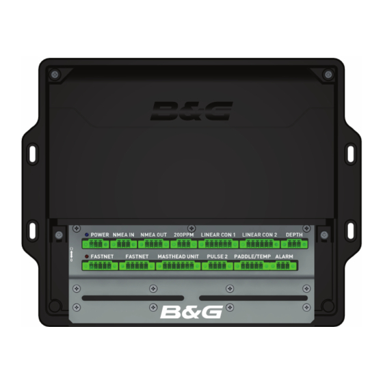
Page 164: Power
H3000 Instrument Handbook POWER POWER TERMINAL COLOUR FUNCTION 12 Volts DC Supply BLUE 0 Volts SCREEN Screen HB-3000-05... -
Page 165: Paddle / Temp
H3000 Instrument Handbook PADDLE / TEMP PADDLE / TEMP TERMINAL COLOUR FUNCTION RED and WHITE 5 Volts DC Supply BLACK 0 Volts GREEN Paddle Input YELLOW / RED Sea Temp Input SCREEN Screen HB-3000-05... -
Page 166: Depth
H3000 Instrument Handbook DEPTH DEPTH TERMINAL COLOUR FUNCTION BLUE Sensor +ve BLACK Sensor -ve SCREEN Screen HB-3000-05... -
Page 167: Nmea Depth
H3000 Instrument Handbook NMEA DEPTH Note: To use NMEA Depth it is necessary to open up the processor and move the terminal jumper to bridge a different set of terminals. Details of how to do this can be found overleaf. - Page 168 H3000 Instrument Handbook Adjusting the terminal jumper to use NMEA Depth Caution: It is recommended that an approved B&G technician performs this operation. Remove terminal cover – 2 x screws Remove top case to expose PCB – 4 x screws Slide off terminal jumper shown below by pulling up.
-
Page 169: Masthead Unit
H3000 Instrument Handbook MASTHEAD UNIT MASTHEAD UNIT TERMINAL COLOUR FUNCTION ORANGE 6.4 Volts DC Supply BLACK 0 Volts Red Wind Angle Phase GREEN Green Wind Angle Phase BLUE Blue Wind Angle Phase VIOLET Wind Speed Input SCREEN Screen HB-3000-05... -
Page 170: Nmea 0183 Interface
H3000 Instrument Handbook NMEA 0183 INTERFACE NMEA IN TERMINAL COLOUR FUNCTION NMEA IN +ve NMEA IN -ve SCREEN Screen NMEA OUT TERMINAL COLOUR FUNCTION NMEA OUT +ve NMEA OUT -ve 0 Volts SCREEN Screen HB-3000-05... -
Page 171: 200 Ppm
H3000 Instrument Handbook 200 PPM 200 PPM TERMINAL COLOUR FUNCTION 200 PPM o/p 0 Volts SCREEN Screen Note: Open Collector, Active Low HB-3000-05... -
Page 172: Linear Inputs
H3000 Instrument Handbook LINEAR INPUTS LINEAR CON 1 TERMINAL COLOUR FUNCTION 6.4 Volts DC Supply BLUE 0 Volts GREEN Air Temperature Sensor Linear 1 Input Linear 2 Input SCREEN Screen LINEAR CON 2 TERMINAL COLOUR FUNCTION 12 Volts DC Supply 6.4 Volts DC Supply... -
Page 173: Fastnet
H3000 Instrument Handbook FASTNET FASTNET TERMINAL COLOUR FUNCTION 12 Volts DC BLACK 0 Volts WHITE Network Data +ve GREEN Network Data -ve SCREEN Screen Note: For Termination of the Network see ‘network installation’ HB-3000-05... -
Page 174: Pulse 2
H3000 Instrument Handbook PULSE 2 PULSE 2 TERMINAL COLOUR FUNCTION 5 Volts DC Supply BLACK 0 Volts GREEN Pulse 2 Input SCREEN Screen HB-3000-05... -
Page 175: Alarm
H3000 Instrument Handbook ALARM ALARM TERMINAL COLOUR FUNCTION Alarm +ve BLUE Alarm -ve SCREEN Screen HB-3000-05... -
Page 176: Halcyon 2000 Compass
H3000 Instrument Handbook HALCYON 2000 COMPASS HB-3000-05... -
Page 177: Heel & Trim Sensors
H3000 Instrument Handbook HEEL & TRIM SENSORS HEEL TERMINAL COLOUR FUNCTION 6.4 Volts DC Supply BLUE Ground GREEN Heel Input TRIM TERMINAL COLOUR FUNCTION 6.4 Volts DC Supply BLUE Ground GREEN Trim Input HB-3000-05... -
Page 178: Air Temp & Barometric Pressure Sensor
H3000 Instrument Handbook AIR TEMP & BAROMETRIC PRESSURE SENSOR AIR TEMPERATURE -LINEAR CON 1 TERMINAL COLOUR FUNCTION 6.4 Volts DC Supply BLUE Ground GREEN Air Temperature Input BAROMETRIC PRESSURE - LINEAR CON 2 TERMINAL COLOUR FUNCTION 12 Volts DC Supply... -
Page 179: Motion Sensor
H3000 Instrument Handbook MOTION SENSOR MOTION SENSOR - LINEAR CON 2 TERMINAL COLOUR FUNCTION 6.4 Volts DC Supply BLACK Ground GREEN Roll Rate VIOLET Pitch Rate SCREEN Screen HB-3000-05... - Page 180 H3000 Instrument Handbook Adjusting the jumper to use USB or RS232 Caution: It is recommended that an approved B&G technician performs this operation. • Remove terminal cover – 2 x screws • Remove top case to expose PCB – 4 x screws •...
-
Page 181: Usb & Rs232
H3000 Instrument Handbook USB & RS232 RS232 COLOUR FUNCTION BROWN BLUE BLACK Ground SCREEN Screen HB-3000-05... -
Page 182: Change Over Switch
H3000 Instrument Handbook CHANGE OVER SWITCH HB-3000-05... -
Page 183: Halcyon Gyro Processor
H3000 Instrument Handbook HALCYON GYRO PROCESSOR GYRO PROCESSOR & GYRO STABILISED COMPASS Note: • All screened wires must have their screen attached to the clamp bar across the front case. • The Halcyon Gyro Stabilised Compass (HGSC) has a separate supply and does not take power from the Network Bus. - Page 184 H3000 Instrument Handbook Terminal Function Wire Colour Cable Network Data (-) Green Network Data (+) White 135-0A-130 4 Cores/Screen Supply Ground Black Supply +ve (12V nom.) AD10 Clock Low (-) AD10 Clock High (+) AD10 Data Low (-) AD10 Data High (+) Ground NMEA Out - (v2.0)
-
Page 185: Halcyon Gyro Processor With Nmea Input
H3000 Instrument Handbook HALCYON GYRO PROCESSOR WITH NMEA INPUT Note: All screened wires must have their screen attached to the clamp bar across the front case. Terminal Function Wire Colour Cable Network Data (-) Green Network Data (+) White 135-0A-130... -
Page 186: Gyro Processor & Gimballed Rate Compass
H3000 Instrument Handbook GYRO PROCESSOR & GIMBALLED RATE COMPASS Terminal Function Wire Colour Cable GRC Supply - Black GRC Supply + Pink GRC Sensor Cable GRC Data + Brown & White GRC Data - Grey & Blue HB-3000-05... -
Page 187: Halcyon Gyro Processor As Output Interface
H3000 Instrument Handbook HALCYON GYRO PROCESSOR AS OUTPUT INTERFACE Note: All screened wires must have their screen attached to the clamp bar across the front case. Heading source must be either a Halcyon 2000 or B&G autopilot. Terminal Function Wire Colour... -
Page 188: Expansion Processor
H3000 Instrument Handbook EXPANSION PROCESSOR The Expansion Unit can be connected to the H3000 system via the Fastnet to provide 12 extra analogue inputs. Once the Expansion processor is connected a new menu will automatically appear on all of the GFDs on the system. Up to 12 linear functions may be displayed numbered LINEAR 5 to LINEAR 16. - Page 189 H3000 Instrument Handbook Expansion Processor Wiring Terminal Function Wire Colour Network Data -ve Green Network Data +ve White Network Screen Screen Battery Supply Ground Black Battery Supply 12V Battery Volts Sense Link to 18 Ground Blue Sensor Supply +6.5V Linear 5 Input...
- Page 190 H3000 Instrument Handbook Sensor Input Confi guration Additional sensors can be added to the system connecting to one of the four linear inputs on the CPU. 12 extra linear inputs are available with the addition of an Expansion Processor. These can be confi gured to take many different sensors. If you connect the sensor to the linear input that B&G have anticipated then you...
-
Page 191: Nmea 0183 Interfacing
NMEA sentence format. Communication Port Confi g The H3000 CPU has two physical port options, USB or RS232 with only one of these being selectable at any one time. Note: The default setup is USB, if the RS232 port is required (to connect a Wireless Port for example) then there is a link connector on the main internal PCB that requires switching. -
Page 192: Displaying Nmea Functions
In addition there are also a number of functions that can be input through the NMEA interface that duplicate other H3000 functions The NMEA functions may be called up to display in the same manner as any H3000 function. Most of the NMEA functions are to be found in the WAYPOINT Menu, but the time functions (LOC Time and UTC) are in the TIME Menu. -
Page 193: Selection Of Equipment
The NMEA 0183 standard defi nes data sentences, which are identifi ed by three letter mnemonics. The NMEA input to the H3000 CPU is designed to version 3.x of the NMEA0183 standard. It does however retain a signifi cant degree of backward compatibility with earlier versions of this standard. -
Page 194: Cpu Nmea Interfacing
H3000 Instrument Handbook CPU NMEA INTERFACING NMEA Input Summary CPU NMEA INPUT Mnemonic Description Autopilot format B Bearing to destination Waypoint from origin Waypoint. Bearing and Distance to Waypoint, Great Circle, measured. Bearing and Distance to Waypoint, Rhumb, measured. Bearing to Waypoint from Waypoint. - Page 195 H3000 Instrument Handbook Proprietary NMEA Input Summary CPU Proprietary NMEA Input Mnemonic Description Polar Speed Knots $PBGTTBS Polar Performance % Distance to Layline (Nm) $PBGTLAY Time to Layline (hh-mm-ss) VMG Upwind (polar) $PBGTVMG Upwind Heading for best VMG (polar) Downwind Heading for best VMG (polar)
- Page 196 H3000 Instrument Handbook NMEA Input Prioritisation The following table shows the order in which the H3000 CPU prioritises incoming NMEA data. CPU NMEA Input Prioritisation Function Bearing to Waypoint Rhumb Bearing to Waypoint GC ºM BWC, APB Bearing to Waypoint GC ºT...
- Page 197 Cross Track Error, Measured Fast HDM Output Option The H3000 CPU NMEA output port may be confi gured independently to output HDM sentences ten times a second for the benefi t of other NMEA instruments that may require a rapid heading update.
-
Page 198: Nmea Ffd Interfacing
H3000 Instrument Handbook NMEA FFD INTERFACING NMEA Input Summary NMEA FFD Input Mnemonic Description Autopilot format B Bearing to destination Waypoint from origin Waypoint Bearing and Distance to Waypoint, Great Circle, measured Bearing and Distance to Waypoint, Rhumb, measured Bearing to Waypoint from Waypoint... - Page 199 Cross Track Error, Dead Reckoned Time and Date Time and Distance to Layline Local Time Zone Time to Waypoint Note: The H3000 system will not necessarily extract data from every NMEA fi eld. This avoids information being duplicated on the system. HB-3000-05...
- Page 200 H3000 Instrument Handbook Proprietary NMEA Input Summary The NMEA FFD also supports the B&G Proprietary Input messages. NMEA Output Summary NMEA FFD Output Mnemonic Description Depth Below Transducer Latitude and Longitude Present Heading, Magnetic Heading Steering Command Heading, True Air Temperature, Celsius...
-
Page 201: Halcyon Gyro Processor Nmea Interfacing
H3000 Instrument Handbook HALCYON GYRO PROCESSOR NMEA INTERFACING NMEA Input Summary Latitude and Longitude (Boat Position) information is only utilised, along with date information, for internal calculation of Magnetic Variation if it has not been received from another source. This input is not required unless utilising True heading references. -
Page 202: True/Magnetic Reference Selection
However in the case of True Heading, via the HDT sentence, if the incoming data is being rapidly updated the network data will be sent at up to four times a second. This allows the data to be used by the H3000 Pilot, if fi tted. HB-3000-05... -
Page 203: H-Link™ Communications
Communication Port Confi guration The H3000 CPU has two physical port options, USB or RS232 with only one of these being selectable at any one time. The default setup is USB with the following communication parameters set:... - Page 204 H3000 Instrument Handbook It is possible to change the port parameters to suit your particular application by accessing the CALBRATE function on COMM CFG in the MISC menu as follows: SETUP CALIBRATION OTHER CALIBRATION MISC COMM There are 4 settings: NMEA MODE Defi...
-
Page 205: Nmea Channel
H3000 Instrument Handbook NMEA CHANNEL Defi nes the output channel(s) in use for NMEA. Value Description USB/RS232 Channel only (NMEA port disabled) NMEA port only, USB/RS232 used for H-Link [default] Both channels (NMEA and USB/RS232) Command Syntax Commands are input as a string of ASCII characters starting with a character and a two-character command mnemonic followed by data fi... - Page 206 #OV (Output Value) command. Similarly, a number of externally generated data functions may be input to the H3000 system by means of the #IV (Input Value) command. #IV is also used to input system parameters to H3000. These two commands are described in more detail as follows:...
- Page 207 If data from a specifi c node is required include the node number here. Note: In most cases it is recommended that this fi eld is left blank, H3000 will output the selected or default data stored within the CPU which is the desired data in almost all cases.
- Page 208 Boat Speed is function number 65 from node 1 and is a function data message type. 1, as such we send: #OV,1,1,65<CR><LF> In this case H3000 will return: V001,001,065,4.37 This indicates a Boat Speed value of 4.37 kt Example 2~ To input a new damping value of 3 seconds on Boat Speed: #IV,1,206,65,3<CR><LF>...
- Page 209 H3000 Instrument Handbook Streaming Output Data #OS (Output Streaming) The #OS command is used to control the streaming of position data, along with normal instrument data. Streaming Output Data #OS (Output Streaming) The #OS command is used to control the streaming of position data, along with normal instrument data.
- Page 210 H3000 Instrument Handbook Then we start streaming data: #OS,1 H3000 will then start to stream data in the standard output format. If we wish to temporarily halt the data we send #OS,0. Table Viewing and Editing #TO (Table Output), #TI (Table Input)
- Page 211 H3000 Instrument Handbook If only the table parameter is in the command then the whole of the selected table will be output. If no parameters are in the command all the system tables will be output. When more than a single cell is output, each output sentence will contain as many cell values from a single row of a single table as will fi...
- Page 212 H3000 Instrument Handbook Example Boat Speed / Heel correction table – Table #0 Column Boat Spd > 0º Heel 10º Heel 20º Heel Example True Wind Angle correction table – Table #1 Column TWS > 40º TWA -7.0 -3.0 -2.5 90º...
-
Page 213: Example Polar Table
H3000 Instrument Handbook EXAMPLE POLAR TABLE True Wind Speed HB-3000-05... - Page 214 H3000 Instrument Handbook Trip and timer control #TC (Trip Control) This command set allows control of the system trip functions, for example Race Timer and Trip Log: Trip Control: #TC,st,d st = Sub Type d = Data Sub Type Data Options...
- Page 215 H3000 Instrument Handbook Examples: Start Countdown Timer: #TC,t,0 Set New Count Down Time to 5 Minutes: #TC,v,5 Freeze Trip Log: #TC,l,2 If the #TC command is sent without any of its parameters the current status of each item (Race Timer, Trip Log, D/R) is reported, in the format.
- Page 216 H3000 Instrument Handbook H3000 Function and Node numbers Function Description Function Node Air Temperature degrees ºC Air Temperature degrees ºF Apparent Wind Angle Apparent Wind Angle, raw Apparent Wind Speed knots Apparent Wind Speed m/s Apparent Wind Speed, raw Average Speed...
- Page 217 H3000 Instrument Handbook Function Description Function Node Distance to Waypoint, G.C. See Note 1 Distance to Waypoint, Rhumb See Note 1 Fore / Aft Trim Heading See Note 2 Heading, Raw See Note 2 Heading on Next Tack Head / Lift Trend...
- Page 218 H3000 Instrument Handbook Function Description Function Node Pitch Rate [Motion] Reaching Performance Remote 0 Remote 1 Remote 2 Remote 3 Remote 4 Remote 5 Remote 6 Remote 7 Remote 8 Remote 9 Roll Rate [Motion] Rudder Angle Sea Temperature degrees ºC Sea Temperature degrees ºF...
-
Page 219: Node
H3000 Instrument Handbook Notes: The source nodes for these functions are dependent on which port or device the GPS is interfaced to. It is assigned as follows: • GPS interfaced to CPU – use Node 5 • GPS interfaced through a NMEA FFD then, typically, Node 96. If there is more than one NMEA FFD on the system then Nodes 97, 98 etc. -
Page 221: System Diagnostics And Troubleshooting
H3000 Instrument Handbook DIAGNOSTICS SYSTEM DIAGNOSTICS AND TROUBLESHOOTING Before getting into a deeper understanding of system diagnostics and trouble shooting there are a few quick and simple items to note: Depth display fl ashes CAL – Simply requires that a new Depth transducer offset value (Datum) is entered via GFD into the CPU. - Page 222 H3000 Instrument Handbook WARNING This must be used with extreme care as all the various confi guration parameters for that unit will be restored to factory default. In the case of the CPU then this will affect all calibrations, alarm and damping settings and will zero all LOG readings for example.
- Page 223 H3000 Instrument Handbook Halcyon Gyro Processor Selecting this option will reset the entire memory of the Halcyon Gyro Processor. Note that the sensor alignment and magnetic deviation compensation parameters will be reset to zero. The Compass readings and all related functions will no longer be accurate until the Compass unit has be re swung and the alignment value correctly entered.
- Page 224 H3000 Instrument Handbook Reset Specifi c Unit This option provides the facility to reset individual, specifi c units that are referenced directly by their FastNet node address. Note the Node address is entered in hexadecimal form as opposed to decimal.
-
Page 225: The Fastnet Databus
H3000 Instrument Handbook THE FASTNET DATABUS The Fastnet bus is fundamental to reliable operation of the H3000 system. It is the principal communication channel for the transferring of data between all units connected around the system. The bus is based on a twisted pair transmit / receive system and requires correct installation to ensure trouble free operation, the key aspects being: •... -
Page 226: H3000 Cpu
H3000 Instrument Handbook H3000 CPU The CPU contains a composite circuit board assembly comprising a larger analogue interface PCB and Depth sounder hardware, plus a small CPU board with removable FLASH memory card. The CPU is principally responsible for measurement of the following sensors and their associated derived functions. -
Page 227: Masthead Unit (Wind Sensor)
H3000 Instrument Handbook MASTHEAD UNIT (WIND SENSOR) If there appears to be a problem with wind speed or wind angle values displayed then its important to view the “raw” data values from the sensor on any GFD. The functions MEAS W/A and MEAS W/S are shown in the WIND menu and will display uncalibrated, raw data from the mast head, as opposed to True Wind say which is derived and has a number of calibrations applied. -
Page 228: Depth Sensor
H3000 Instrument Handbook fully operational.. The problem therefore is likely up the mast cable or possibly the electronics PCB inside the MHU. • MEAS W/S appears to read slow – The most likely cause here is worn anemometer bearings, more likely if the MHU is a few years. - Page 229 H3000 Instrument Handbook Yacht Stationary Symptom: Display consistently shows: ____ ____ ____ ____ when well within the range of the sounder when the yacht is stationary in the water. This is an indication that no consistent signal is being received by the depth sounder.
- Page 230 H3000 Instrument Handbook • The gain of the receiver has been set too low. It is possible to adjust the maximum gain via CAL VAL1 on gain. This is normally set to 30 and should not be adjusted. Yacht Moving...
- Page 231 H3000 Instrument Handbook water. It is impossible to give specifi c instructions on where to re-site the transducer as it is dependent on the design of boat; however better results will be obtained nearer the centre line of the boat.
- Page 232 H3000 Instrument Handbook Random Deep Depths Symptom: Display shows random deep depths. Possible Causes: • Electrical noise. The depth sounder contains circuits and software to reduce its susceptibility to electrical noise, however this can still be a problem if not installed carefully or other equipment is not correctly suppressed.
-
Page 233: Halcyon 2000 Compass
H3000 Instrument Handbook HALCYON 2000 COMPASS Heading and CAL Flashing Symptom: Display fl ashes a Heading value and “CAL” Possible Causes: • The memory in the Halcyon 2000 is empty or has been corrupted. This may be due to a System Reset being performed or the fi rst time the compass has been installed and not yet been calibrated. - Page 234 H3000 Instrument Handbook Two Headings Flashing Alternately Symptom: The Pilot Display shows two headings fl ashing alternately Possible Causes: The Pilot has not been set to use the Halcyon 2000 as its heading source. Refer to Heading Source selection in your Instrument or Pilot Handbook. If the Halcyon 2000 is not to be the source of heading then it must be unplugged from the system.
-
Page 235: Routine Maintenance
H3000 Instrument Handbook ROUTINE MAINTENANCE GENERAL MAINTENANCE Through-hull housings Keep the screw threads of through-hull housings well greased with silicone or water pump grease. Ensure that the outer surfaces of the housing are properly coated with anti-fouling paint. Boat speed sensor (paddlewheel type) Use a stiff brush to remove marine growth that may cause the paddlewheel to freeze, and then clean the surfaces with a very weak solution of household detergent. -
Page 236: Winter Storage/Laying Up
H3000 Instrument Handbook WINTER STORAGE/LAYING UP Masthead unit Storage of the masthead unit when the yacht is laid up afl oat will increase the life of the transmitters. It should always be removed from the masthead before the mast is unstepped. -
Page 237: H3000 System Calibration Record
H3000 Instrument Handbook H3000 SYSTEM CALIBRATION RECORD System Confi guration Record Function Default Setting User Setting Heading Node 16 (Halcyon 2000) Halcyon Mode 4 (Heel) 5 (Trim) Linears 6 (Barometer) 1 (0-1000 Type) NMEA Chl Baud Rate Sea Temp Type... - Page 238 H3000 Instrument Handbook True Wind Speed Correction Table True Wind Speed Function Correction º Correction Angle True Wind Angle Correction Table True Wind Speed Wind Angle Upwind Reaching Downwind Boat Speed Correction Table Boat Speed (kt) Heel Angle 0º 10º...
-
Page 239: Damping Record
H3000 Instrument Handbook DAMPING RECORD Function Damping Dynamic Damping App W/A App W/S Heading Boat Spd Heel Trim Leeway Mast Angle Rudder True W/A True W/S True Dir Tide HB-3000-05... -
Page 240: Support Record
H3000 Instrument Handbook SUPPORT RECORD Engineer / Date Notes Dealer HB-3000-05...
Need help?
Do you have a question about the h3000 and is the answer not in the manual?
Questions and answers