
Related Manuals for B&G RAM T2


Summary of Contents for B&G RAM T2
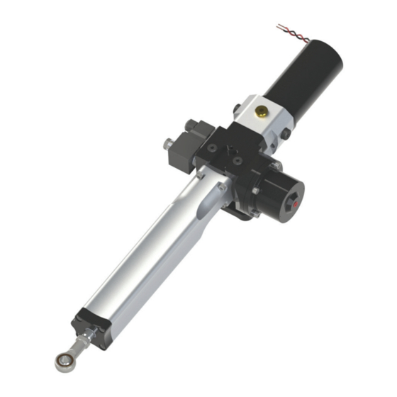
- Page 1 RAM T1 & T2 Marine Linear Actuator User Manual ENGLISH bandg.com simrad-yachting.com...
- Page 2 This precision engineered product was designed and manufactured in the United Kingdom. Please keep this manual in a safe place The information in this manual was, to the best of our knowledge, correct when it went to press and Simrad or B&G cannot be liable for any inaccuracies or omissions.
-
Page 3: Table Of Contents
CONTENTS Page 4 Important Safety Information Compliance Statement Emergency Quick Release Emergency Steering Description Performance • Technical Data Dimensions Actuator Selection Location Tiller bolt Mounting Foot Quadrant Considerations ... -
Page 4: Important Safety Information
IMPORTANT SAFETY INFORMATION Failure to install and maintain this equipment in accordance with the instructions contained in this Manual could result in damage or injury. This equipment must be installed and maintained by a person who is qualified to do so. This equipment is only for use with marine autopilots within the limitations stated in the following pages. -
Page 5: Emergency Quick Release
EMERGENCY QUICK RELEASE In the unlikely event of failure of the actuator a quick release R-Clip is fitted to the tiller bolt which secures the actuator to the steering quadrant. Pull the red tab to release the R-Clip and then manually lift the actuator clear of the steering quadrant. -
Page 6: Description
Internal relief valves protect the unit and its mountings from rudder strikes, grounding etc. PERFORMANCE Hard over time Typical max thrust seconds at 5 kg RAM T1 RAM T2... -
Page 7: Technical Data
T1 = 12 VDC, T2 = 12 / 24 VDC Current Typical Amp-hour Typical Current 60 kg at 25% duty Intermittent 650 kg RAM T1 19.0 RAM T2 25.0 12.0 Ingress protection IP67 EMC Protection BS EN 60945:2002 (DC) Ignition Protection... -
Page 8: Dimensions
DIMENSIONS... -
Page 9: Actuator Selection
RAM T1 13 sec 190 mm 120 kg 13 sec 213 mm 140 kg 13 sec 245 mm 160 kg RAM T2 9 sec 190 mm 120 kg 9 sec 213 mm 140 kg 9 sec 245 mm 160 kg Hard over time is the time to move the cylinder full stroke (255 mm at 5 kg) Typical max torque intermittent is calculated at 650 kg thrust. -
Page 10: Location
LOCATION The RAM T1 & T2 Actuators are designed for under-deck installations only. When considering where to mount the actuator the following points should be taken into account. : Keep cable runs short : Mount away from sources of heat : Install the actuator above areas liable to flooding. -
Page 11: Tiller Bolt
TILLER BOLT The tiller bolt supplied is suitable for a quadrant thickness of 12 to 16 mm. The tiller bolt mounting hole should be drilled Ø12.2 to 12.3 mm. An application of Loctite 638 or equivalent where shown is recommended. Tighten the M12 nut to 27 Nm Torque WASHER TILLER BOLT... -
Page 12: Quadrant
QUADRANT Typical installation for an 8.4” (213 mm) radius with total rudder angle of 70 degrees. CONSIDERATIONS Allow sufficient clearance for removal of the mounting pin (Ref. page 17) and rod end from the tiller bolt. COIL CONNECTIONS NOT USED PIN 1 POSITIVE PIN 2... -
Page 13: Servicing
MAINTAINANCE The RAM T1/T2 is a sealed unit, quality precision engineering will ensure many years of trouble free service if the following points are adhered to. : Keep the piston rod free from damage : Avoid exposing the unit to salt water. Perform the following checks regularly: : Check the security of the mounting bolts and tiller pin. - Page 14 The motor is a non-serviceable item and should be replaced with a new motor and drive coupling Kit. Part Nos. 12V UNITS = R4510-sk 12 100 X 24V UNITS = R4510-sk 24 100 X Quote your units serial number when ordering Ref. page 19).. The motor can be replaced without affecting the integrity of the hydraulic circuit.
-
Page 15: Fault Finding
FAULT FINDING Under no circumstances dismantle the unit unless it is certain that the fault is internal. Doing so will allow air into the cylinder, requiring the unit to be bled for which special tools are needed. Ref. page 13. Caution Any damage to the piston rod will damage its seals and allow air into the cylinder and oil leaks. -
Page 16: Hydraulic Fluid
HYDRAULIC FLUID Caution Do not use Brake fluid Use mineral based good quality hydraulic fluid compatible with nitrile hy- draulic seals. Ref Technical Data on page COMMISSIONING Caution Be aware of the danger of moving linkages and the risk of entrapment. The unit is pre-filled and sealed from new. -
Page 17: Dismounting The Unit From Its Base
DISMOUNTING THE UNIT FROM ITS BASE The RAM T1/T2 features a quick-dismount base. To remove the base from the unit first take off the coil which is secured by a 17 mm A/F nut. Next undo and remove the Allen screw ‘A’ and the retaining plate ‘B’... -
Page 18: Dimensions For Mounting Foot
DIMENSIONS FOR MOUNTING FOOT (NOT TO SCALE) -
Page 19: General Information
GENERAL INFORMATION Keep this manual in a safe place. Quote the model and serial numbers in all correspondence. Model Number: ________________________________ Serial Number: ________________________________ Date of Purchase: ________________________________ Dealer: ________________________________ ________________________________ ________________________________ CONTACT DETAILS For inquiries in general, contact Simrad or B&G: www.simrad-yachting.com www.bandg.com For inquiries of spare parts, contact Hydraulic Projects Limited:...
Need help?
Do you have a question about the RAM T2 and is the answer not in the manual?
Questions and answers