
Related Manuals for Sony Trimaster PVM-2541A


Summary of Contents for Sony Trimaster PVM-2541A
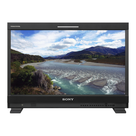
- Page 1 4-461-017-11(1) Professional Video Monitor Operating Instructions Before operating the unit, please read this manual thoroughly and retain it for future reference. PVM-2541A PVM-1741A © 2012 Sony Corporation...
- Page 2 The model and serial numbers are located at the rear. Record these numbers in the spaces provided below. THIS APPARATUS MUST BE EARTHED. Refer to these numbers whenever you call upon your Sony dealer regarding this product. WARNING When installing the unit, incorporate a readily Model No.____________________ accessible disconnect device in the fixed wiring, or Serial No.____________________...
- Page 3 2. Providing protective earth If you have questions on the use of the above Power When this product is installed in a rack and is supplied Cord / Appliance Connector / Plug, please consult a power from an outlet on the rack, please confirm that the qualified service personnel.
- Page 4 (commercial and light industrial), E3 (urban outdoors), E4 (controlled EMC environment, ex. TV studio). This product has been manufactured by or on behalf of Sony Corporation, 1-7-1 Konan Minato-ku Tokyo, 108- 0075 Japan. Inquiries related to product compliance based on European Union legislation shall be addressed...
-
Page 5: Table Of Contents
Table of Contents Precaution .............. 6 On Safety ............6 On Installation ............ 6 Handling the Screen ........... 6 On Burn-in ............6 On a Long Period of Use ........6 Handling and Maintenance of the Screen ..7 On Dew Condensation ........7 On Repacking ............. -
Page 6: Precaution
always on (red, green, or blue), or flashing. In Precaution addition, over a long period of use, because of the physical characteristics of the panel, such “stuck” pixels may appear spontaneously. These problems are not a malfunction. On Safety • Do not leave the screen facing the sun as it can damage the screen. -
Page 7: Handling And Maintenance Of The Screen
In addition, the screen is panel blinks in green and amber for fan error indication, vulnerable to damage. Do not scratch or knock against it turn off the power and contact an authorized Sony using a hard object. dealer. -
Page 8: Features
Sony’s Super Top Emission OLED panel Both 17-type and 25-type models include a full HD (1920 × 1080) OLED panel featuring Sony’s Super Top Emission technology. Unlike the conventional bottom Features... - Page 9 25. Monitor stand with tilt function Color space function PVM-2541A and PVM-1741A can be mounted on the You can select any of three color space settings (EBU/ optional SU-561 Monitor Stand with tilt and height SMPTE-C/ITU-R BT.709). adjustment. You can select the height of the monitor by adjusting the stand.
-
Page 10: Location And Function Of Parts And Controls
Location and Function of Parts and Controls Front Panel SDI 1 SDI 2 HDMI COMPOSITE RETURN MENU a Tally lamp COMPOSITE button: to monitor the signal through the COMPOSITE IN connector You can check the status of the monitor by the color of the tally lamp. - Page 11 When the menu is displayed, turn the control to select a menu item or setting value, and then press the control to confirm the setting. If the menu is not displayed and the menu selection control is pressed, the characters that represent the names of the buttons light up.
-
Page 12: Input Signals And Adjustable/Setting Items
Input Signals and Adjustable/Setting Items Input signal Item Composite HDMI/DVI* Color B & W CONTRAST BRIGHTNESS* × CHROMA × × × × × × PHASE (NTSC) APERTURE COLOR TEMP COLOR SPACE × × × × × × × AUTO CHROMA/PHASE ×... -
Page 13: Rear Panel
Rear Panel PVM-2541A COMPOSITE AUDIO PARALLEL SERIAL REMOTE REMOTE 5 6 7 PVM-1741A COMPOSITE AUDIO PARALLEL SERIAL REMOTE REMOTE a SDI (3G/HD/SD) input and output connectors b COMPOSITE input and output connectors (BNC) (BNC) 1 (input) connector, 2 (input) connector IN connector Input connector for serial digital component signals. - Page 14 Follow the instructions for this port. e SERIAL REMOTE connector (RJ-45) Connect to the network or Sony BKM-15R/16R Monitor Control Unit by using a 10BASE-T/100BASE- TX LAN cable (shielded type, optional).
-
Page 15: Removing The Monitor Stand (Pre-Attached)
Put the monitor on a soft cloth with the surface of Attach the mounting bracket to the monitor with the monitor downward. supplied screws. Remove the three screws. PVM-2541A Attach the unit to the rack with four screws. Note The screws are not supplied. Prepare screws according PVM-1741A to the rack. -
Page 16: Adjusting The Height Of The Monitor (With Su-561 Only)
PVM-2541A and PVM-1741A can be mounted on the optional SU-561 Monitor Stand. You can adjust the COMPOSITE AUDIO height of the monitor on three levels (for PVM-2541A) or four levels (for PVM-1741A) by changing the PARALLEL SERIAL REMOTE REMOTE position of the stand attachment bracket and the arm attachment position. -
Page 17: Connecting The Ac Power Cord
Attach the arm cover. Connecting the AC To remove the stand and stand Power Cord attachment bracket Put the monitor on a soft cloth with the surface of Plug the AC power cord into the AC IN socket on the monitor downward. the rear panel. -
Page 18: Selecting The Default Settings
Selecting the Default Settings When you turn on the unit for the first time after purchasing it, select the area where you intend to use this SDI 1 SDI 2 HDMI COMPOSITE RETURN MENU unit from among the options. The default setting values for each area RETURN MENU Press the 1 (standby) switch. -
Page 19: Selecting The Menu Language
2 If LATIN AMERICA is selected: Selecting the Menu PAL&PAL-N area Language L A T I N A M E R I C A P A L & P A L - N A R E A Argentina A R G E N T I N A P A R A G U A Y Paraguay U R U G U A Y... -
Page 20: Using The Menu
The setting items (icons) in the selected menu are Using the Menu displayed in yellow. USER CONFIG – SYSTEM SETTING 1/2 The unit is equipped with an on-screen menu for making xxxxxx N T S C S E T U P : xxxxxx F O R M AT D I S P L AY: various adjustments and settings such as picture control,... - Page 21 The menu icon presently selected is shown in The menu disappears automatically if a button is not yellow and setting items are displayed. pressed for one minute. About the memory of the settings USER CONFIG – SYSTEM SETTING 1/2 xxxxxx N T S C S E T U P : The settings are automatically stored in the monitor xxxxxx...
-
Page 22: Adjustment Using The Menus
RGB RANGE Adjustment Using the SCREEN SAVER Menus FLICKER FREE SD PIXEL MAPPING MARKER SETTING MARKER ENABLE Items MARKER SELECT CENTER MARKER The screen menu of this monitor consists of the SAFETY AREA following items. MARKER LEVEL MARKER MAT T/C DISPLAY SETTING STATUS (the items indicate the current settings.) FORMAT... -
Page 23: Adjusting And Changing The Settings
• Color temperature Adjusting and Changing the Settings • HDMI format • Gamma STATUS menu • Flicker free The STATUS menu is used to display the current status • Model name and serial number of the unit. The following items are displayed: COLOR TEMP/SPACE menu For the video input The COLOR TEMP/SPACE menu is used for adjusting... -
Page 24: User Control Menu
Submenu Setting Submenu Setting COLOR SPACE Selects the color space from among EBU, SMPTE-C, ITU-709 and SUB CONTROL Adjusts finely the adjustment range OFF. OFF sets the color space to of the function buttons which the original color reproduction of BRIGHTNESS is assigned. -
Page 25: User Config Menu
Submenu Setting Submenu Setting INPUT SETTING • SHIFT H: Adjusts the position of FORMAT DISPLAY Selects the display mode of the the picture. As the setting signal format and scan mode. increases, the picture moves • OFF: The display is hidden. to the right, and as the •... - Page 26 Submenu Setting Submenu Setting I/P MODE (picture delay Selects to set the delay by the SCREEN SAVER Sets the screen saver function on or minimum) picture processing to the minimum off. level when the interlace signal is • ON: If a still image is displayed input.
- Page 27 MARKER SETTING T/C (time code) DISPLAY SETTING USER CONFIG – MARKER SETTING USER CONFIG – T/C DISPLAY SETTING M A R K E R E N A B L E : T / C : M A R K E R S E L E C T : F O R M AT : C E N T E R M A R K E R : P O S I T I O N :...
- Page 28 Submenu Setting Submenu Setting WFM/ALM/ Sets the display settings for WFM/ALM/ When VECTOR is selected VECTOR vectorcope. • WFM: Displays the wave form Audio level Magenta monitor. (dB) • ALM: Displays the audio level meter. OVER • VECTOR: Displays the vectorscope. When WFM is selected, the waveform Bar I and audio level are displayed.
- Page 29 FOCUS SETTING About the function assigned to the function button USER CONFIG – FOCUS SETTING SCAN F O C U S M O D E : Press the button to change the scan size of the picture. C O L O R : With every press of the button, the picture switches in F R E Q U E N C Y: R A N G E :...
-
Page 30: Scan Mode Image
BRIGHTNESS Press the button to display the adjustment screen and Press the button to display the time code display. Adjust adjust the picture brightness. Press again to hide the the settings for the time code display in T/C DISPLAY adjustment screen. However, the picture brightness SETTING (see page 27). - Page 31 CLOSED CAPTION SETTING Submenu Setting CAPTION LEVEL Sets the luminance of the displayed characters. Select LOW or HIGH. USER CONFIG – CLOSED CAPTION SETTING C L O S E D C A P. : Note T Y P E : 7 0 8 : You can change the setting only 6 0 8 :...
-
Page 32: Remote Menu
REMOTE menu Submenu Setting PARALLEL REMOTE Selects the PARALLEL REMOTE REMOTE connector pins for which you want PA R A L L E L R E M O T E : to change the function. You can assign various functions to S E R I A L R E M O T E : xxxxxxx M O N I T O R :... - Page 33 SERIAL REMOTE Submenu Setting FORCED TALLY The tally lamp function is forcibly assigned to 7 pin and 8 pin of the Submenu Setting PARALLEL REMOTE connector. SERIAL REMOTE Selects the mode to be used. Selecting ON assigns tally lamp • OFF: SERIAL REMOTE does green to 7 pin and tally lamp red to not function.
-
Page 34: Key Inhibit Menu
KEY INHIBIT menu Troubleshooting KEY INHIBIT K E Y I N H I B I T : This section may help you isolate the cause of a problem and as a result, eliminate the need to contact technical support. • The unit cannot be operated t The key protection function works. -
Page 35: Specifications
1920 × 1080 pixels (Full HD) Aspect 16:9 General Pixel efficiency 99.99% Power PVM-2541A: AC 100 to 240 V, 1.4 A Panel drive RGB 10-bit to 0.6 A, 50/60 Hz Viewing angle (Panel specification) 89º/89º/89º/89º (typical) PVM-1741A: AC 100 to 240 V, 1.0 A (up/down/left/right, contrast >... -
Page 36: Available Signal Formats
– 1080/30PsF* – – Always verify that the unit is operating properly before – 1080/24p* use. SONY WILL NOT BE LIABLE FOR – 1080/25p DAMAGES OF ANY KIND INCLUDING, BUT NOT LIMITED TO, COMPENSATION OR – 1080/30p* REIMBURSEMENT ON ACCOUNT OF THE LOSS –... - Page 37 Applicable DVI input signals from PC When a DVI signal is input to the HDMI IN connector using a DVI conversion cable Resolution Dot clock fH (kHz) fV (Hz) (MHz) 640 × 480 25.175 31.5 1280 × 768 68.250 47.4 1280 ×...
-
Page 38: Dimensions
Side Dimensions 110 (4 80 (3 PVM-2541A 40 (1 Front 576 (22 40 (1 171.4 (6 SDI 1 SDI 2 HDMI COMPOSITE RETURN MENU Front (with optional monitor stand SU-561) 442 (17 Rear 400 (15 100 (4) SDI 1 SDI 2... - Page 39 PVM-1741A Front (with optional monitor stand SU-561) Front 436 (17 320 (12 322 (12 Side (with optional monitor stand SU-561) Rear 389.6 (15 100 (4) 66 (2 269.9 (10 Unit: mm (inches) Mass: Approx. 7.2 kg (15 lb 14 oz) Side Approx.
- Page 40 Sony Corporation...
Need help?
Do you have a question about the Trimaster PVM-2541A and is the answer not in the manual?
Questions and answers