Sony PVM-2541 Operating Instructions Manual
Professional video monitor
Hide thumbs
Also See for PVM-2541:
- Operating instructions manual (76 pages) ,
- Manual (36 pages) ,
- Interface manual for programmers (13 pages)

Related Manuals for Sony PVM-2541


Summary of Contents for Sony PVM-2541
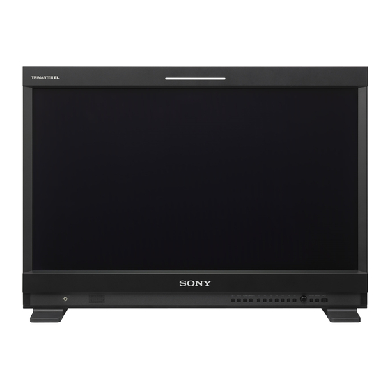
- Page 1 4-284-713-13(1) Professional Video Monitor Operating Instructions Before operating the unit, please read this manual thoroughly and retain it for future reference. PVM-2541 PVM-1741 © 2011 Sony Corporation...
- Page 2 The model and serial numbers are located at the rear. Record these numbers in the spaces provided below. THIS APPARATUS MUST BE EARTHED. Refer to these numbers whenever you call upon your Sony dealer regarding this product. WARNING When installing the unit, incorporate a readily Model No.____________________ accessible disconnect device in the fixed wiring, or Serial No.____________________...
- Page 3 2. Providing protective earth If you have questions on the use of the above Power When this product is installed in a rack and is supplied Cord / Appliance Connector / Plug, please consult a power from an outlet on the rack, please confirm that the qualified service personnel.
- Page 4 Electromagnetic Environments: E1 (residential), E2 (commercial and light industrial), E3 (urban outdoors), E4 (controlled EMC environment, ex. TV studio). The manufacturer of this product is Sony Corporation, 1-7-1 Konan, Minato-ku, Tokyo, 108-0075 Japan. The Authorized Representative for EMC and product safety is Sony Deutschland GmbH, Hedelfinger Strasse 61, 70327 Stuttgart, Germany.
-
Page 5: Table Of Contents
Table of Contents Precaution .............. 6 On Safety ............6 On Installation ............ 6 Handling the Screen ........... 6 On Burn-in ............6 On a Long Period of Use ........6 Handling and Maintenance of the Screen ..7 On Dew Condensation ........7 On Repacking ............. -
Page 6: Precaution
always on (red, green, or blue), or flashing. In Precaution addition, over a long period of use, because of the physical characteristics of the panel, such “stuck” pixels may appear spontaneously. These problems are not a malfunction. On Safety • Do not leave the screen facing the sun as it can damage the screen. -
Page 7: Handling And Maintenance Of The Screen
In addition, the screen is panel blinks in green and amber for fan error indication, vulnerable to damage. Do not scratch or knock against it turn off the power and contact an authorized Sony using a hard object. dealer. -
Page 8: Features
You can select any of three color space settings (EBU/ Sony’s Super Top Emission OLED panel SMPTE-C/ITU-R BT.709). Both 17-type and 25-type models include a full HD (1920 × 1080) OLED panel featuring Sony’s Super Top Emission technology. Unlike the conventional bottom Features... - Page 9 10 minutes. Rack mount PVM-2541 and PVM-1741 support the VESA (100 × 100) standard. The PVM-1741 can also be mounted on an EIA-standard 19-inch rack. For more information, see “Installing on a Rack (PVM- 1741 only)”...
-
Page 10: Location And Function Of Parts And Controls
Location and Function of Parts and Controls Front Panel SDI 1 SDI 2 HDMI COMPOSITE RETURN MENU a Tally lamp COMPOSITE button: to monitor the signal through the COMPOSITE IN connector You can check the status of the monitor by the color of the tally lamp. - Page 11 When the menu is displayed, turn the control to select a menu item or setting value, and then press the control to confirm the setting. To light up the characters that represent the names of the buttons When the menu is not displayed, press the menu selection control.
-
Page 12: Input Signals And Adjustable/Setting Items
Input Signals and Adjustable/Setting Items Input signal Item Composite HDMI/DVI* Color B & W CONTRAST BRIGHT* × CHROMA × × × × × × PHASE (NTSC) APERTURE COLOR TEMP COLOR SPACE × × × × × × × AUTO CHROMA/PHASE ×... -
Page 13: Rear Panel
Rear Panel PVM-2541 COMPOSITE AUDIO PARALLEL SERIAL REMOTE REMOTE 5 6 7 PVM-1741 COMPOSITE AUDIO PARALLEL SERIAL REMOTE REMOTE a SDI (3G/HD/SD) input and output connectors b COMPOSITE input and output connectors (BNC) (BNC) 1 (input) connector, 2 (input) connector IN connector Input connector for serial digital component signals. - Page 14 Follow the instructions for this port. e SERIAL REMOTE connector (RJ-45) Connect to the network or Sony BKM-15R/16R Monitor Control Unit by using a 10BASE-T/100BASE- TX LAN cable (shielded type, optional).
-
Page 15: Removing The Monitor Stand (Pre-Attached)
Put the monitor on a soft cloth with the surface of Attach the mounting bracket to the monitor with the monitor downward. supplied screws. Remove the three screws. PVM-2541 Attach the unit to the rack with four screws. Note The screws are not supplied. Prepare screws according PVM-1741 to the rack. -
Page 16: Adjusting The Height Of The Monitor (With Su-561 Only)
PVM-2541 and PVM-1741 can be mounted on the optional SU-561 Monitor Stand. You can adjust the COMPOSITE AUDIO height of the monitor on three levels (for PVM-2541) or four levels (for PVM-1741) by changing the position of PARALLEL SERIAL REMOTE... -
Page 17: Connecting The Ac Power Cord
Attach the arm cover. Connecting the AC To remove the stand and stand Power Cord attachment bracket Put the monitor on a soft cloth with the surface of Plug the AC power cord into the AC IN socket on the monitor downward. the rear panel. -
Page 18: Selecting The Default Settings
Selecting the Default Settings When you turn on the unit for the first time after purchasing it, select the area where you intend to use this SDI 1 SDI 2 HDMI COMPOSITE RETURN MENU unit from among the options. The default setting values for each area RETURN MENU Press the 1 (standby) switch. -
Page 19: Selecting The Menu Language
2 If LATIN AMERICA is selected: Selecting the Menu PAL&PAL-N area Language L A T I N A M E R I C A P A L & P A L - N A R E A Argentina A R G E N T I N A P A R A G U A Y Paraguay U R U G U A Y... -
Page 20: Using The Menu
The setting items (icons) in the selected menu are Using the Menu displayed in yellow. USER CONFIG – SYSTEM SETTING 1/2 The unit is equipped with an on-screen menu for making xxxxxx N T S C S E T U P : xxxxxx F O R M AT D I S P L AY: various adjustments and settings such as picture control,... - Page 21 The menu icon presently selected is shown in The menu disappears automatically if a button is not yellow and setting items are displayed. pressed for one minute. About the memory of the settings USER CONFIG – SYSTEM SETTING 1/2 xxxxxx N T S C S E T U P : The settings are automatically stored in the monitor xxxxxx...
-
Page 22: Adjustment Using The Menus
RGB RANGE Adjustment Using the SCREEN SAVER Menus FLICKER FREE MARKER SETTING MARKER ENABLE MARKER SELECT Items CENTER MARKER SAFETY AREA The screen menu of this monitor consists of the MARKER LEVEL following items. MARKER MAT T/C DISPLAY SETTING STATUS (the items indicate the FORMAT current settings.) POSITION... -
Page 23: Color Temp/Space Menu
For the video input COLOR TEMP/SPACE menu The COLOR TEMP/SPACE menu is used for adjusting the picture white balance or color space. STATUS 1 / 2 You need to use the measurement instrument to adjust F O R M AT xxxxxxxxx xxxxxxxx the white balance. - Page 24 Submenu Setting USER CONTROL 1/3 AUTO CHROMA/ Adjusts color intensity (CHROMA) S U B C O N T R O L PHASE and tones (PHASE). B R I G H T N E S S : • AUTO ADJ VALUE: Selects A P E R T U R E : ON or OFF of the auto V O L U M E :...
-
Page 25: User Config Menu
USER CONFIG menu Submenu Setting The USER CONFIG menu is used for setting the GAMMA Select the appropriate gamma mode system, marker, T/C display, WFM/ALM display, from among 2.4, 2.2, and CRT. If you select the CRT mode while function button, and audio. either ITU-709 or OFF is selected in COLOR SPACE, gamma settings are adjusted to those in the... - Page 26 Submenu Setting Submenu Setting Selects a format for DVI input MARKER SELECT Selects the aspect ratio according to signal. the film, when the frame of the film • PC: For RGB signal format is displayed on the screen. • VIDEO: For YP signal When 16:9 aspect ratio is selected format...
- Page 27 Submenu Setting Submenu Setting TRANSPARENCY Selects BLACK or HALF (transparent) for the background of When WFM is selected T/C display. Waveform Audio level • BLACK: The background becomes black. Displayed (dB) image is hidden behind the OVER 109% background. 100% •...
- Page 28 remains adjustable. Turn the menu selection control right to increase the brightness and turn left to decrease Submenu Setting F1 BUTTON to F7 Assigns the function to the function BUTTON buttons of the front panel and turns the CONTRAST function on or off. Press the button to display the adjustment screen and You can assign the function from among SCAN, ASPECT, BLUE ONLY,...
-
Page 29: Remote Menu
An OLED panel can provide superior video responsiveness and scan driving, reproducing images Submenu Setting with little contouring or afterimaging. However, scan SDI AUDIO SETTING Sets the audio channel when SDI driving can cause flicker when input signals have a low signal is input. - Page 30 Submenu Setting Submenu Setting FORCED TALLY The tally lamp function is forcibly assigned to 7 pin and 8 pin of the PARALLEL REMOTE Selects the PARALLEL REMOTE PARALLEL REMOTE connector. connector pins for which you want Selecting ON assigns tally lamp to change the function.
-
Page 31: Key Inhibit Menu
SERIAL REMOTE KEY INHIBIT menu Submenu Setting KEY INHIBIT K E Y I N H I B I T : SERIAL REMOTE Selects the mode to be used. • OFF: SERIAL REMOTE does not function. • ETHERNET: The monitor is controlled by the command of Ethernet. -
Page 32: Troubleshooting
KEY INHIBIT menu. Effective picture size (H × V) Or, a function that does not work is assigned. Press the PVM-2541: 543.4 × 305.6 mm RETURN button to check the assigned functions. × 12 inches) • The black bars appear at the upper and lower PVM-1741: 365.8 ×... - Page 33 Optional accessories Monitor stand General SU-561 Power PVM-2541: AC 100 to 240 V, 1.4 A to 0.6 A, 50/60 Hz Design and specifications are subject to change without PVM-1741: AC 100 to 240 V, 1.0 A to notice. 0.5 A, 50/60 Hz DC 12 V, 7.0 A...
-
Page 34: Available Signal Formats
You can allocate functions using the REMOTE menu Resolution Dot clock fH (kHz) fV (Hz) (see page 29). (MHz) Wiring required to use the Remote Control 640 × 480 25.175 31.5 Connect the function you want to use with a Remote 1280 ×... -
Page 35: Dimensions
Side Dimensions 110 (4 80 (3 PVM-2541 40 (1 Front 576 (22 40 (1 171.4 (6 SDI 1 SDI 2 HDMI COMPOSITE RETURN MENU Front (with optional monitor stand SU-561) 442 (17 Rear 400 (15 100 (4) SDI 1 SDI 2... - Page 36 PVM-1741 Front (with optional monitor stand SU-561) Front 436 (17 320 (12 322 (12 Side (with optional monitor stand SU-561) Rear 389.6 (15 100 (4) 66 (2 269.9 (10 Unit: mm (inches) Mass: Approx. 7.2 kg (15 lb 14 oz) Side Approx.
- Page 37 Sony Corporation...
Need help?
Do you have a question about the PVM-2541 and is the answer not in the manual?
Questions and answers