Table of Contents
Advertisement
Advertisement
Table of Contents

Related Manuals for TVS electronics RP-3200


Summary of Contents for TVS electronics RP-3200
- Page 1 LINE THERMAL PRINTER MODEL RP-3200 User’ s Manual...
- Page 2 SAFETY PRECAUTIONS ...WHICH SHOULD BE STRICTLY OBSERVED Before using this product for the first time, carefully read these SAFETY PRECAUTIONS. Improper handling may result in accidents (fire, electric shock or injury). In order to prevent injury to operators, third parties, or damage to property, special warning symbols are used in the User’...
- Page 3 PRECAUTIONS ON PRINTER INSTALLATION WARNING Do not use or store this product in a place where it will be exposed to: * Flames or moist air. * Direct sunlight. * Hot airflow or radiation from a heating device. * Salty air or corrosive gases. * Ill-ventilated atmosphere.
- Page 4 CAUTION Do not use the printer under the following conditions. Avoid locations subject to vibration or instability. Avoid locations where the printer is not level. · The printer may fall and cause an injury. · The quality of printing may deteriorate. Do not obstruct the printer’...
- Page 5 PRECAUTIONS IN HANDLING THE PRINTER WARNING Please observe the following precautions for power source and power cord: Do not plug or unplug the power cord with a wet hand. Use the printer only at the specified supply voltage and frequency. Use only the specified AC adapter with the printer.
- Page 6 CAUTION Caution label is attached in the position shown in the following figure. Carefully read the handling precautions before using the printer. THIS LABEL INDICATES THE RISK OF BURNS DUE TO THE HIGH TEMPERATURE OF THE PRINT HEAD AND A RISK OF BEING CUT BY THE MANUAL AND AUTO CUTTERS WHILE THE PAPER COVER IS OPEN.
-
Page 7: Daily Maintenance
CAUTION To prevent injury and printer failures from worsening, observe the following: While the paper cover is open, be careful to not touch the manual cutter that is in the paper eject slot. Do not touch the printing surface of the thermal head. Do not touch any of the moving parts (e.g., paper cutter, gears, active electric parts) while the printer is working. -
Page 8: Table Of Contents
THE TABLE OF CONTENTS 1. GENERAL OUTLINE ..............9 Features ..................9 Basic Specifications..............10 2. EXPLANATION OF PRINTER PARTS ........11 2.1 Printer Appearance..............11 2.2 Inside the paper cover..............14 2.3 Other Built-in Functions .............. 15 3. SETUP..................16 3.1 Connecting the AC Power Cord.......... -
Page 9: General Outline
1. GENERAL OUTLINE The RP-3200 line thermal printer series is designed for use with a broad array of terminal equipment including data, POS, and kitchen terminals. These printers have extensive features so they can be used in a wide range of applications. -
Page 10: Basic Specifications
1.2 Basic Specifications Item Specifications Model RP-3200 Print method Line thermal dot print method Print width 80 mm/640 dots, 72 mm/576 dots, 64 mm/512 dots, 54.5 mm/436 dots, 54 mm/432 dots, 52.5 mm/420 dots, 48 mm/384 dots, 45 mm/360 dots, 48.75 mm/390 dots, 68.25 mm/546 dots... -
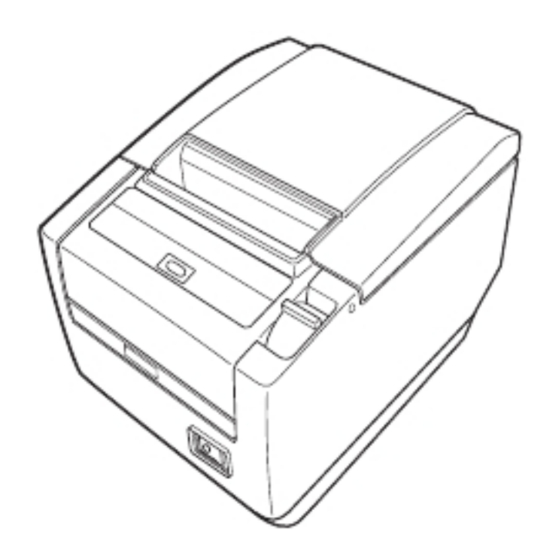
Page 11: Explanation Of Printer Parts
2. EXPLANATION OF PRINTER PARTS 2.1 Printer Appearance Names of parts Paper cover Cover open lever Operation panel Front cover Power switch Rear connectors Front cover release button Maintenance cover (Front view) (Rear view) Paper cover Open to load paper. Cover open lever Use this lever to open the paper cover. - Page 12 Power switch Press this button to turn the power on or off. Maintenance cover Not applicable for this product. CAUTION Do not open the maintenance cover. Operation panel PAPER LED POWER LED (green) ERROR LED (red) (orange) FEED button POWER LED (green) Lights when the power is on, turns off when the power is off.
- Page 13 Rear connectors Cash drawer Interface connector Power connector (AC adapter type) kick-out (serial, parallel, USB, etc.) connector AC inlet (built-in power supply type) Interface connector (serial, parallel, USB, etc.) Connects to the interface cable. The serial interface board is equipped with a DIP switch. Cash drawer kick-out connector Connects to the cable from the cash drawer.
-
Page 14: Inside The Paper Cover
2.2 Inside the paper cover Paper-end sensor (PE sensor) Platen Auto cutter Button to change paper near-end sensor Manual cutter Print head (thermal) Paper thickness selection lever Paper near-end sensor (PNE sensor) Platen Feeds the paper. Paper near-end sensor (PNE sensor) Detects when the paper is near the end of the roll. -
Page 15: Other Built-In Functions
Paper thickness selection lever Use this lever to select regular or thick paper according to the thickness of the paper being loaded. CAUTION Do not change the position of the paper thickness selection lever from the factory setting. Refer to 3.8 Setting Paper Thickness 2.3 Other Built-in Functions Buzzer Buzzes when errors occur or when operations or command operations are... -
Page 16: Setup
3. SETUP 3.1 Connecting the AC Power Cord Turn off the power. For the built-in power type printer, connect the AC power cord to the AC inlet, and insert the plug into an electric outlet. For the AC adapter type printer, connect the cable connector of the AC adapter to the power connector. -
Page 17: Connecting Interface Cables
3.2 Connecting Interface Cables Turn off the power. Orient the interface cable correctly and insert it into the interface connector. Parallel interface Serial interface USB interface (hub type) USB interface Serial , Ethernet , USB interface [hub type] and Powered USB interfaces are available as options in addition to those listed here. -
Page 18: Connecting The Cash Drawer
Use a serial interface cable with the connection layout shown below. 25-pin - 25-pin cable 9-pin - 25-pin cable Printer Printer Signal Signal Signal CAUTION Place the interface cable so people do not trip on it. 3.3 Connecting the Cash Drawer Turn off the power. - Page 19 (1) Connector pin configuration Signal Connector used: TM5RJ3-66 (Hirose) or equivalent Applicable connector: TM3P-66P (Hirose) or equivalent (2) Electric characteristics 1) Drive voltage: 24 VDC 2) Drive current: Approx. 1 A max. (not to exceed 510 ms.) 3) DRSW signal: Signal levels: “ L” = 0 to 0.8 V, “...
-
Page 20: Precautions For Installing The Printer
3.4 Precautions for Installing the Printer The printer can be used horizontally, vertically, or installed on a wall. However, the RP-3200 (built-in power supply type) cannot be used vertically or installed on a wall. Use the optional stand for vertical applications, and the optional brackets for wall installations. -
Page 21: Partition For Paper Roll
3.5 Partition for Paper Roll Set the partition to the width of the paper roll you are loading. The partition is set at the factory to the position shown below. For 3-inch type: 80-mm wide paper roll For 2-inch type: 58-mm wide paper roll Turn off the power. -
Page 22: Setting The Dip Switch On The Serial Interface Board
3.6 Setting the DIP Switch on the Serial Interface Board Turn off the printer and unplug the power cord from the electric outlet. Remove the mounting screws of the serial interface board. Remove the serial interface board from the printer. Set the DIP switch according to the following table. -
Page 23: Adjusting The Paper Near-End Sensor
3.7 Adjusting the Paper Near-end Sensor Change the settings of the paper near-end sensor to set the position at which the near-end of the paper is detected. Use a pointed object, such as a pen, to gently press the button to change the paper near-end sensor. -
Page 24: Setting Paper Thickness
3.8 Setting Paper Thickness Set the paper thickness selection lever to the thickness of the paper. (Thick paper can only be used with the label-printing model) To get the best print quality, do not change the factory settings unless printing on thick paper or there is a problem with the print density. -
Page 25: Loading Paper
3.9 Loading Paper Press the cover open lever while the power is on. Open the paper cover. Load the paper roll so that the printable side of the paper is facing down, as shown by arrow A. Pull a few cm of paper straight out in the direction of arrow B. Close the paper cover in the direction of arrow C until you hear a click. -
Page 26: Attaching The Power Switch Cover
3.10 Attaching the Power Switch Cover Attach this cover to prevent the power switch from being used. Press the power switch cover onto the power switch compartment until it clicks. Power switch cover Put a screwdriver or other pointed object into the grooves on the power switch cover to remove it. -
Page 27: Attaching The Interface Cover
The shape of the interface cover is different depending on the type of power source. Press the interface cover as shown in the diagram until you hear it click. RP-3200 3.12 Removing the Interface Cover Press in on both sides at the point indicated by A to remove the interface cover. -
Page 28: Maintenance And Troubleshooting
4. MAINTENANCE AND TROUBLESHOOTING 4.1 Periodic Cleaning A dirty print head or platen may reduce printing quality or cause malfunctions. Also, if paper dust collects on the sensor’ s protective sheet, paper cannot be detected correctly. We recommend cleaning the printer periodically (every 2 to 3 months) as shown below. -
Page 29: Clearing A Cutter Lock (1)
4.2 Clearing a Cutter Lock (1) The ERROR LED flashes and the auto cutter blade remains extended because a foreign object or paper jam is obstructing it. If the ERROR LED is flashing, clear the locked cutter as shown below. Press the cover open lever while the power is on. -
Page 30: Clearing A Cutter Lock (2)
4.3 Clearing a Cutter Lock (2) The paper cover is designed to be opened if the cutter locks by pressing the cover open lever. If this does not open the paper cover, use the following procedure to clear the locked cutter. Turn off the printer and unplug the power cord from the electric outlet. -
Page 31: Self-Printing
CAUTION Before starting to do maintenance work, be sure to turn off the printer and unplug the power cord from the electric outlet. Be careful not to touch the manual cutter while the front cover is open. Be careful not to touch the opening for the auto cutter while the paper cover is open. The print head is hot immediately after printing. -
Page 32: Hexadecimal Dump Printing
4.5 Hexadecimal Dump Printing Print received data in hexadecimal. If problems such as missing or duplicated data occur, this function allows you to check whether or not the printer is receiving data correctly. How to do hexadecimal dump printing Load paper. While the paper cover is open, press and hold the FEED button while turning the power on, and then close the paper cover. -
Page 33: Error Messages
4.6 Error Messages Paper-end The end of the roll of paper is detected at two stages, paper near-end and paper-end. When paper near-end is detected, the PAPER LED lights. Prepare a new paper roll. When paper end is detected, the PAPER LED and ERROR LED light. Load a new paper roll. - Page 34 The status display for various messages is shown below. Signal Signal Signal Notes: *1: If the paper cover or front cover is open in standby. *2: If the paper cover or front cover is open when printing or feeding paper. *3: Buzzer sounds when MSW5-1 (buzzer setting) is set to ON.
-
Page 35: Other
5. OTHER 5.1 External Views and Dimensions (Unit: mm) Built-in power supply type AC adapter type — 35 —... -
Page 36: Printing Paper
5.2 Printing Paper Use the paper shown in the following table or paper of the same quality. Signal (Unit: mm) Printable side Paper width 83 Paper width 80 Maximum print area 80 Maximum print area 72 Paper width 60 Paper width 58 Maximum print area 48 Maximum print area 48 (Initial setting) -
Page 37: Manual Setting Of Memory Switches
5.3 Manual Setting of Memory Switches Memory switches are used to set various printer settings. The memory switches can be set manually (set by hand on the printer) or by commands. This section explains how to perform manual settings. For information on how to set the memory switches using commands, please refer to the Command Reference. - Page 38 Individual setting mode Set the memory switches individually. Do the settings while confirming the memory switch function and settings on the printout. Load paper. While the paper cover is open, press and hold the FEED button while turning the power on. Press the FEED button twice and close the paper cover.
- Page 39 Press the FEED button for at least two seconds. A setting for the memory switch is printed, through the cycle, each time the FEED button is pressed for at least two seconds. Press the FEED button for at least two seconds to cycle through the list until the function of the memory switch you want to change is printed.
- Page 40 The function of each memory switch is shown in the following table. (Shaded values are factory settings.) Switch no. Function MSW1-1 Power ON Info Valid Not Send MSW1-2 Buffer Size 4K bytes 45 bytes MSW1-3 Busy Condition Full/Err Full MSW1-4 Receive Error Print“...
- Page 41 Switch no. Function MSW1-1 Power ON Info Valid Not Send MSW1-2 Buffer Size 4K bytes 45 bytes MSW1-3 Busy Condition Full Full/Err MSW1-4 Receive Error Print“ ?” No Print MSW1-5 CR Mode Ignored MSW1-6 Reserved Fixed — MSW1-7 DSR Signal Invalid Valid MSW1-8...
Need help?
Do you have a question about the RP-3200 and is the answer not in the manual?
Questions and answers
i want the ppd file to get it installed in my ubuntu machine