
Related Manuals for TVS electronics RP-4150


Summary of Contents for TVS electronics RP-4150
- Page 1 LINE THERMAL PRINTER LINE THERMAL PRINTER LINE THERMAL PRINTER LINE THERMAL PRINTER MODEL MODEL MODEL MODEL RP RP- - - - 4150 4150 4150 4150 User User User User’ ’ ’ ’ s Manual s Manual s Manual s Manual...
- Page 2 SAFETY PRECAUTIONS ... SAFETY PRECAUTIONS ... SAFETY PRECAUTIONS ... SAFETY PRECAUTIONS ... WHICH SHOULD BE STRICTLY OBSERVED WHICH SHOULD BE STRICTLY OBSERVED WHICH SHOULD BE STRICTLY OBSERVED WHICH SHOULD BE STRICTLY OBSERVED Before using this product for the first time, carefully read these SAFETY PRECAUTIONS. Improper handling may result in accidents (fire, electric shock or injury).
- Page 3 PRECAUTIONS ON PRINTER INSTALLATION PRECAUTIONS ON PRINTER INSTALLATION PRECAUTIONS ON PRINTER INSTALLATION PRECAUTIONS ON PRINTER INSTALLATION WARNING WARNING WARNING WARNING ■ Do not use or store this product in a place where it will be exposed * Flames or moist air. * Direct sunlight.
- Page 4 CAUTION CAUTION CAUTION CAUTION Do not use the printer under the following conditions. ■ A state subject to vibration or unstable state. ■ A state with this product slanted. · · · · Otherwise dropping may cause injury. Otherwise dropping may cause injury. Otherwise dropping may cause injury.
- Page 5 PRECAUTIONS IN HANDLING THE PRINTER PRECAUTIONS IN HANDLING THE PRINTER PRECAUTIONS IN HANDLING THE PRINTER PRECAUTIONS IN HANDLING THE PRINTER WARNING WARNING WARNING WARNING Please observe the following precautions for power source and power cord: ■ Do not plug or unplug the power cord with a wet hand. ■...
- Page 6 CAUTION CAUTION CAUTION CAUTION Caution label is attached on the position shown in the following figure. Carefully read the precautions in handling before using the printer. THESE LABELS INDICATE THE THESE LABELS INDICATE THE THESE LABELS INDICATE THE THESE LABELS INDICATE THE RISK OF ANY INJURY DUE TO RISK OF ANY INJURY DUE TO RISK OF ANY INJURY DUE TO...
- Page 7 CAUTION CAUTION CAUTION CAUTION To prevent injury and printer failures from worsening, observe the following: ■ Do not touch the printing surface of the thermal head. ■ Do not touch any of the moving parts (e.g., paper cutter, gears, active electrical parts) while the printer is working.
-
Page 8: Table Of Contents
THE TABLE OF CONTENTS THE TABLE OF CONTENTS THE TABLE OF CONTENTS THE TABLE OF CONTENTS 1. GENERAL OUTLINE ...... 1. GENERAL OUTLINE ..............9 1. GENERAL OUTLINE ...... 1. GENERAL OUTLINE ..............9 ..........9 ..........9 Features ..................9 Unpacking ..................10 Model Classification .............. -
Page 9: General Outline
1. GENERAL OUTLINE 1. GENERAL OUTLINE 1. GENERAL OUTLINE 1. GENERAL OUTLINE This product are thermal line printers designed for use with a broad array of terminal equipment including data, POS, and kitchen terminals. With extensive features, they can be used in a wide range of applications. 1.1 Features 1.1 Features 1.1 Features... -
Page 10: Unpacking
When unpacking the printer, confirm that the following are provided: ● Printer: ● AC power cord : ● User’ s manual (This manual): 1 roll ● Sample paper roll: ● Partition: ● Screw: User’ s manual AC power cord (This manual) RP-4150 Sample paper roll Partition Screw -10-... -
Page 11: Basic Specifications
AC100 to 240V, 50/60 Hz, 130VA / DC24V, 2.0A Power consumption Approx. 70W (in normal printing) Weight Approx. 2.3 Kg for RP-4150 Outside dimensions 177 (W) ⋅ 213 (D) ⋅ 147 (H) mm Operating temperature 5 to 45°C, 10 to 90% RH (No condensation) -
Page 12: Explanation Of Printer Parts
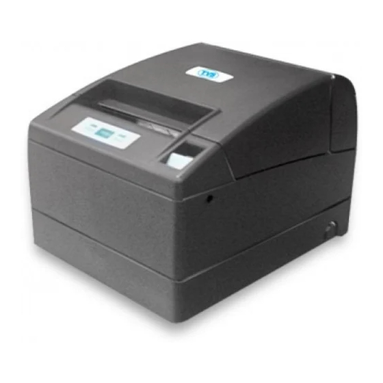
2. 2. 2. 2. EXPLANATION OF PRINTER PARTS EXPLANATION OF PRINTER PARTS EXPLANATION OF PRINTER PARTS EXPLANATION OF PRINTER PARTS 2.1 Printer Appearance 2.1 Printer A ppearance 2.1 Printer A 2.1 Printer A ppearance ppearance Printer cover Cover open button Side opening Power switch Rear connector... - Page 13 Operation Operation Panel Operation Operation Panel Panel Panel POWER LED ERROR LED FEED button ● POWER LED Illuminated when the printer power is on and off when the printer power is off. May blink or light in a special mode or in case of failure. ●...
-
Page 14: Printer Cover Inside
2.2 Printer Cover Inside 2.2 Printer Cover Inside 2.2 Printer Cover Inside 2.2 Printer Cover Inside Manual cutter ● Paper feed roller Feeds paper as part of print Paper feed roller mechanism. Paper-end sensor ● Paper-near-end sensor Detects near paper end, change position in accordance with the Print (thermal) head... -
Page 15: Preparation
3. PREPARATION 3. PREPARATION 3. PREPARATION 3. PREPARATION 3.1 Connecting the AC Power Cord 3.1 Connecting the AC Power Cord 3.1 Connecting the AC Power Cord 3.1 Connecting the AC Power Cord 1. Turn off the printer power switch. 1. Turn off the printer power switch. 1. -
Page 16: Connecting Interface Cables
3.2 Connecting Interface Cables 3.2 Connecting Interface Cables 3.2 Connecting Interface Cables 3.2 Connecting Interface Cables Confirm that the power switch is OFF and connect the interface cable. Orient the interface cable terminal correctly and insert it into the interface connector. -
Page 17: Connecting The Cash Drawer
3.3 Connecting the Cash Drawer 3.3 Connecting the Cash Drawer 3.3 Connecting the Cash Drawer 3.3 Connecting the Cash Drawer 1. Confirm that the power switch is OFF. 1. Confirm that the power switch is OFF. 1. Confirm that the power switch is OFF. 1. -
Page 18: Installing The Printer
3.4 Installing the Printer 3.4 Installing the Printer 3.4 Installing the Printer 3.4 Installing the Printer The printer can be installed horizontally, vertically, and on the wall. At the time of shipment, the printer is set for horizontal installation. To install the printer vertically or on the wall, the following adjustments are required. -
Page 19: Setting Dip Switch
3.6 Setting DIP Switch 3.6 Setting DIP Switch 3.6 Setting DIP Switch 3.6 Setting DIP Switch The DIP switch is present on the serial interface board. The function of each switch is as shown below. DIP switch Interface board mounting screws CAUTION! CAUTION! CAUTION! -
Page 20: Adjusting The Paper Near-End Sensor
3.7 Adjusting the Paper Near 3.7 Adjusting the Paper Near- - - - end Sensor 3.7 Adjusting the Paper Near 3.7 Adjusting the Paper Near end Sensor end Sensor end Sensor 1. Lightly push in the paper near 1. Lightly push in the paper near- - - - end sensor unit. end sensor unit. -
Page 21: Maintenance And Troubleshooting
4. 4. 4. 4. MAINTENANCE AND TROUBLESHOOTING MAINTENANCE AND TROUBLESHOOTING MAINTENANCE AND TROUBLESHOOTING MAINTENANCE AND TROUBLESHOOTING 4.1 Setting/Replacing the paper roll 4.1 Setting/Replacing the paper roll 4.1 Setting/Replacing the paper roll 4.1 Setting/Replacing the paper roll 1. Pull the cover open button forward. 1. -
Page 22: Periodic Cleaning
4.3 Periodic cleaning 4.3 Periodic cleaning 4.3 Periodic cleaning 4.3 Periodic cleaning If the print head or platen is dirty, clear printing is not available or fault may occur. If paper dust or the like is present on the sensor protection sheet, label paper or blackmark paper may not be detected correctly. -
Page 23: Self-Printing
4.4 Self- - - - printing 4.4 Self printing 4.4 Self 4.4 Self printing printing Insert paper into the printer. With the FEED button pressed and held, turn the printer power on, keep the FEED button held for about 1 second, and then release the FEED button. -
Page 24: Error Indication
4.6 Error Indication 4.6 Error Indication 4.6 Error Indication 4.6 Error Indication ● Paper end Paper out is detected in two steps: paper near-end and paper end. ERROR LED will light when the paper is empty. If paper end is detected, refill the paper. If the printer cover is open, a paper-end is detected. -
Page 25: When The Paper Cover Cannot Be Opened
Lighting and blinking status of each error including the above is shown below. Status Status Status Status POWER POWER LED POWER POWER ERROR LED ERROR LED ERROR LED ERROR LED Buzzer Buzzer Buzzer Buzzer Paper-end Lights Lights Paper near-end Lights Lights Printer cover open Lights... -
Page 26: Other
5. OTHER 5. OTHER 5. OTHER 5. OTHER 5.1 External Views and Dimensions 5.1 External Views and Dimensions 5.1 External Views and Dimensions 5.1 External Views and Dimensions (Unit: mm) 5.2 Printing Paper 5.2 Printing Paper 5.2 Printing Paper 5.2 Printing Paper Use the print paper shown in the following table or the paper with equivalent quality. - Page 27 a) Label paper *L Full cut position Paper feeding Unit: mm direction Item Item Dimensions Dimensions Item Item Dimensions Dimensions Liner width 58 to 112 Label width 54 to 108 +_ 0.5 Left edge of label 2 + 0.5 Print width 50 to 104 Top margin 2 +_ 1...
- Page 28 b) Black mark paper (BM paper) Cut position Printable area Paper feeding direction Black Mark (printed on the reverse) Unit: mm Item Item Dimensions Dimensions Item Item Dimensions Dimensions Right edge of black mark 15 or more Left edge of black mark 0 to 1.5 Black mark height Cut position in black mark...
-
Page 29: Manual Setting Of Memory Switch
5.3 Manual Setting of Memory Switch 5.3 Manual Setting of Memory Switch 5.3 Manual Setting of Memory Switch 5.3 Manual Setting of Memory Switch Memory switches can be set manually or by a command. For manual setting, refer to the next page. The function of each memory switch is shown in the following table. - Page 30 Mark Mark Mark Mark Item Item Item Item Dimensions Dimensions Dimensions Dimensions Right edge of black mark 15 or more Left edge of black mark 0 to 1.5 Black mark height Cut position in black mark Top margin 6.5 / 12 Black mark pitch 30 to 300 Bottom margin...
- Page 31 Entering memory switch setting mode. Set paper in the printer and keep the printer cover open. With the FEED button pressed and held, turn the printer power on, and then press the FEED button twice. Close the cover. If the current settings of the memory switch etc.
-
Page 32: Selecting Paper Type
5.4 Selecting Paper Type 5.4 Selecting Paper Type 5.4 Selecting Paper Type 5.4 Selecting Paper Type *L, *M *L, *M *L, *M *L, *M Paper type selection is available by the combination of memory switches SW4- 4 and SW4-5 by the used of “ Memory Switch Select Mode” . In addtion, the following procedure is available. - Page 33 Black Mark sensor Label light receiving sensor *L Metal frame Level indicator Black Mark paper Label paper sensor adjuster *L sensor adjuster Label light emitting sensor *L 1 Enter Adjusting Paper Sensor mode. 1 Enter Adjusting Paper Sensor mode. 1 Enter Adjusting Paper Sensor mode. 1 Enter Adjusting Paper Sensor mode.
-
Page 34: Full Cutting Label Paper
5.6 Full cutting label paper 5.6 Full cutting label paper 5.6 Full cutting label paper 5.6 Full cutting label paper *L *L *L *L When full-cutting the label paper with the printer installed horizontally,Be sure that the guide plate is mounted on the paper exit of the printer cover. (This guide plate was set to the printer at the time of factory shipment.) The Guide Plate prevents cut paper from dropping in the printer.
Need help?
Do you have a question about the RP-4150 and is the answer not in the manual?
Questions and answers