
Subscribe to Our Youtube Channel
Related Manuals for TVS electronics RP-3300


Summary of Contents for TVS electronics RP-3300
- Page 1 LINE THERMAL PRINTER LINE THERMAL PRINTER LINE THERMAL PRINTER LINE THERMAL PRINTER MODEL MODEL RP RP- - - - 3300 3300 MODEL MODEL 3300 3300 User User User User’ ’ ’ ’ s Manual s Manual s Manual s Manual...
- Page 2 SAFETY PRECAUTIONS SAFETY PRECAUTIONS SAFETY PRECAUTIONS SAFETY PRECAUTIONS ...WHICH SHOULD BE STRICTLY OBSERVED ...WHICH SHOULD BE STRICTLY OBSERVED ...WHICH SHOULD BE STRICTLY OBSERVED ...WHICH SHOULD BE STRICTLY OBSERVED Before using this product for the first time, carefully read these SAFETY PRECAUTIONS. Improper handling may result in accidents (fire, electric shock or injury).
- Page 3 PRECAUTIONS ON PRINTER INSTALLATION PRECAUTIONS ON PRINTER INSTALLATION PRECAUTIONS ON PRINTER INSTALLATION PRECAUTIONS ON PRINTER INSTALLATION WARNING WARNING WARNING WARNING Do not use or store this product in a place where it will be exposed to: * Flames or moist air. * Direct sunlight.
- Page 4 CAUTION CAUTION CAUTION CAUTION Do not use the printer under the following conditions. Avoid locations subject to vibration or instability. Avoid locations where the printer is not level. · · · · The printer may fall and caus The printer may fall and cause an injury. e an injury.
- Page 5 PRECAUTIONS IN HANDLING THE PRINTER PRECAUTIONS IN HANDLING THE PRINTER PRECAUTIONS IN HANDLING THE PRINTER PRECAUTIONS IN HANDLING THE PRINTER WARNING WARNING WARNING WARNING Please observe the following precautions for power source and power cord: Do not plug or unplug the power cord with a wet hand. Use the printer only at the specified supply voltage and frequency.
- Page 6 CAUTION CAUTION CAUTION CAUTION Caution label is attached in the position shown in the following figure. Carefully read the handling precautions before using the printer. THIS LABEL INDICATES THE THIS LABEL INDICATES THE THIS LABEL INDICATES THE THIS LABEL INDICATES THE RISK OF BURNS DUE TO THE RISK OF BURNS DUE TO THE RISK OF BURNS DUE TO THE...
- Page 7 CAUTION CAUTION CAUTION CAUTION To prevent injury and printer failures from worsening, observe the following: While the paper cover is open, be careful to not touch the manual cutter that is in the paper eject slot. Do not touch the printing surface of the thermal head. Do not touch any of the moving parts (e.g., paper cutter, gears, active electric parts) while the printer is working.
- Page 8 THE TABLE OF CONTENTS THE TABLE OF CONTENTS THE TABLE OF CONTENTS THE TABLE OF CONTENTS 1. GENERAL OUTLINE ..............1. GENERAL OUTLINE ..............2 2 2 2 1. GENERAL OUTLINE ..............1. GENERAL OUTLINE ..............
-
Page 9: Table Of Contents
Features ..................2 Basic Specifications..............3 2. EXPLANATION OF PRINTER PARTS ........2. EXPLANATION OF PRINTER PARTS ........4 4 4 4 2. EXPLANATION OF PRINTER PARTS ........2. EXPLANATION OF PRINTER PARTS ........2.1 Printer Appearance..............4 2.2 Inside the Paper Cover ..............7 2.3 Other Built-in Functions .............. -
Page 10: Features
1. GENERAL OUTLINE 1. GENERAL OUTLINE The RP-3300 line thermal printer series is designed for use with a broad array of terminal equipment including data, POS, and kitchen terminals. These printers have extensive features so they can be used in a wide range of applications. -
Page 11: Basic Specifications
Specifications Specifications Specifications Specifications Model RP-3300 Print method Line thermal dot print method Print width 80 mm/640 dots, 72 mm/576 dots, 64 mm/512 dots, 54.5 mm/436 dots, 54 mm/432 dots, 52.5 mm/420 dots, 48 mm/384 dots, 45 mm/360 dots, 48.75 mm/390 dots, 68.25 mm/546 dots... -
Page 12: Explanation Of Printer Parts
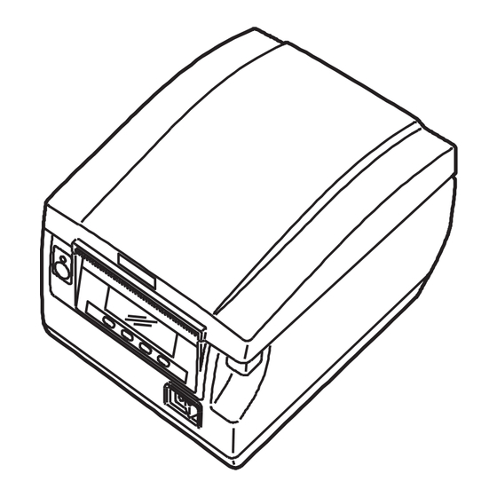
2. EXPLANATION OF PRINTER PARTS 2. EXPLANATION OF PRINTER PARTS 2. EXPLANATION OF PRINTER PARTS 2. EXPLANATION OF PRINTER PARTS 2.1 Printer Appearance 2.1 Printer Appearance 2.1 Printer Appearance 2.1 Printer Appearance Names of parts Names of parts Names of parts Names of parts Paper cover Operation panel... - Page 13 Operation panel Operation panel Operation panel Operation panel LOCK icon PAPER LOW FEED FEED Button 1 to Button 4 FEED button Button 1 (FEED) Button 4 (MENU) Examples are shown in the diagram of the LCD above on the right. Indicates the printer’...
- Page 14 Rear connectors Rear connectors Rear connectors Rear connectors Cash drawer Interface connector Power connector (AC adapter type) kick-out (serial, parallel, USB, etc.) connector External device connector Protective seal AC inlet (built-in power supply type) Interface connector (serial, parallel, USB, etc.) Connects to the interface cable.
-
Page 15: Inside The Paper Cover
2.2 Insi 2.2 Inside the Paper Cover 2.2 Insi 2.2 Insi de the Paper Cover de the Paper Cover de the Paper Cover Print head (thermal) Manual cutter Button to change paper near-end sensor Paper near-end sensor Paper thickness (PNE sensor) selection lever (blue) Auto cutter Paper-end sensor... -
Page 16: Other Built-In Functions
Paper end sensor (PE sensor) Detects when there is no paper. Printing stops when this sensor detects there is no paper. Paper thickness selection lever (blue) Use this lever to select regular or thick paper according to the thickness of the paper being loaded. -
Page 17: Setup
3. SETUP 3. SETUP 3. SETUP 3. SETUP 3.1 Connecting the AC Power Cord 3.1 Connecting the AC Power Cord 3.1 Connecting the AC Power Cord 3.1 Connecting the AC Power Cord 1. 1. 1. 1. Turn off the power. Turn off the power. -
Page 18: Connecting Interface Cables
3.2 Connecting Interface Cables 3.2 Connecting Interface Cables 3.2 Connecting Interface Cables 3.2 Connecting Interface Cables 1. 1. 1. 1. Turn off the power. Turn off the power. Turn off the power. Turn off the power. 2. 2. 2. 2. Orient the interface cable correctly and insert it into the interface connector. - Page 19 CAUTION CAUTION CAUTION CAUTION Always unplug the AC adapter from the printer before connecting the Always unplug the AC adapter from the printer before connecting the Always unplug the AC adapter from the printer before connecting the Always unplug the AC adapter from the printer before connecting the printer to a Powered USB interface.
-
Page 20: Connecting The Cash Drawer
3.3 Connecting the Cash Drawer 3.3 Connecting the Cash Drawer 3.3 Connecting the Cash Drawer 3.3 Connecting the Cash Drawer 1. 1. 1. 1. Turn off the power. Turn off the power. Turn off the power. Turn off the power. 2. - Page 21 (1) Connector pin configuration Signal Signal Signal Signal Function Function Function Function Frame ground Connector used: TM5RJ3-66 (Hirose) or DRAWER1 Cash drawer 1 drive signal equivalent DRSW Cash drawer switch input Applicable connector: Cash drawer drive power supply TM3P-66P (Hirose) or equivalent DRAWER2 Cash drawer 2 drive signal...
-
Page 22: Connecting An External Device
3.4 Connecting an External Device 3.4 Connecting an External Device 3.4 Connecting an External Device 3.4 Connecting an External Device 1. 1. 1. 1. Turn off the power. rn off the power. rn off the power. rn off the power. 2. -
Page 23: Precautions For Installing The Printer
3.5 Precautions for Installing the Printer 3.5 Precautions for Installing the Printer 3.5 Precautions for Installing the Printer 3.5 Precautions for Installing the Printer This printer can only be positioned horizontally. It cannot be positioned vertically or on a wall. Vertical position Horizontal position CAUTION... -
Page 24: Partition For Paper Roll
3.6 Partition for Paper 3.6 Partition for Paper Roll 3.6 Partition for Paper 3.6 Partition for Paper Roll Roll Roll Set the partition to the width of the paper roll you are loading. The partition is set at the factory to the position shown below. For 3-inch type: 80-mm wide paper roll For 2-inch type: 58-mm wide paper roll 1. -
Page 25: Setting The Dip Switch On The Serial Interface Board
3.7 Setting the DIP Switch on the Serial 3.7 Setting the DIP Switch on the Serial 3.7 Setting the DIP Switch on the Serial 3.7 Setting the DIP Switch on the Serial Interface Board Interface Board Interface Board Interface Board 1. -
Page 26: Adjusting The Paper Near-End Sensor
3.8 Adjusting the Paper Near 3.8 Adjusting the Paper Near- - - - end Sensor 3.8 Adjusting the Paper Near 3.8 Adjusting the Paper Near end Sensor end Sensor end Sensor Change the settings of the paper near-end sensor to set the position at which the near-end of the paper is detected. -
Page 27: Setting Paper Thickness
3.9 Setting Paper Thickness 3.9 Setting Paper Thickness 3.9 Setting Paper Thickness 3.9 Setting Paper Thickness Set the paper thickness selection lever (blue) to the thickness of the paper. 1. 1. 1. 1. Turn off the power. Turn off the power. Turn off the power. -
Page 28: Loading Paper
3.10 Loading Paper 3.10 Loading Paper 3.10 Loading Paper 3.10 Loading Paper 1. 1. 1. 1. Turn on the p Turn on the power. Turn on the p Turn on the p ower. ower. ower. 2. 2. 2. 2. Press up on the cover open button to open the paper cover. Press up on the cover open button to open the paper cover. -
Page 29: Attaching The Power Switch Cover
3.11 Attaching the Power Switc 3.11 Attaching the Power Switch Cover 3.11 Attaching the Power Switc 3.11 Attaching the Power Switc h Cover h Cover h Cover Attach this cover to prevent the power switch from being used. 1. 1. 1. 1. Press the power switch cover onto the power switch compartment until it clicks. -
Page 30: Attaching The Interface Cover
Press the interface cover as shown in the diagram until you hear it click. Press the interface cover as shown in the diagram until you hear it click. Press the interface cover as shown in the diagram until you hear it click. RP-3300 3.13 Removing the Inte 3.13 Removing the Interface Cover 3.13 Removing the Inte... -
Page 31: Maintenance And Troubleshooting
4. MAINTENANCE AND TROUBLESHOOTING 4. MAINTENANCE AND TROUBLESHOOTING 4. MAINTENANCE AND TROUBLESHOOTING 4. MAINTENANCE AND TROUBLESHOOTING 4.1 Periodic Cleaning 4.1 Periodic Cleaning 4.1 Periodic Cleaning 4.1 Periodic Cleaning A dirty print head or platen may reduce printing quality or cause malfunctions. Also, if paper dust collects on the sensor’... -
Page 32: Clearing A Cutter Lock (1)
4.2 Clearing a Cutter Lock (1) 4.2 Clearing a Cutter Lock (1) 4.2 Clearing a Cutter Lock (1) 4.2 Clearing a Cutter Lock (1) The message “ Cutter lock” may appear and the auto cutter blade may remain extended because a foreign object or paper jam is obstructing it. FEED If “... - Page 33 7. 7. 7. 7. Close the front cover. Close the front cover. Close the front cover. Close the front cover. Rotate the front cover in the opposite direction of arrow A, and push on the top of the front cover until it clicks. Load a paper roll and close the paper cover.
-
Page 34: Function Test Mode
4.4 Function Test Mode 4.4 Function Test Mode 4.4 Function Test Mode 4.4 Function Test Mode Press and hold button 1 while turning on the printer to access the function test mode. Use button 3 ( ) to select a function, use button 4 ( ) to execute the function. Except for the self test and printing memory switch settings, all functions are for service personnel only. - Page 35 Printing memory switch settings Printing memory switch settings Printing memory switch settings Printing memory switch settings 1. 1. 1. 1. While paper is loaded, press and hold button 1 while turning the power on. While paper is loaded, press and hold button 1 while turning the power on.
-
Page 36: Key Lock Function
4.5 Key Lock Function 4.5 Key Lock Function 4.5 Key Lock Function 4.5 Key Lock Function Press and hold the MENU button while the printer is running to be able to change the memory switch settings. Activate the key lock to prevent making changes by mistake. LOCK icon FEED Button 3... -
Page 37: Hexadecimal Dump Printing
4.6 Hexadecimal Dump Printing 4.6 Hexadecimal Dump Printing 4.6 Hexadecimal Dump Printing 4.6 Hexadecimal Dump Printing Print received data in hexadecimal. If problems such as missing or duplicated data occur, this function allows you to check whether or not the printer is receiving data correctly. -
Page 38: Error Messages
4.7 Error Messages 4.7 Error Messages 4.7 Error Messages 4.7 Error Messages Paper end The end of the roll of paper is detected at two stages, paper near-end and paper-end. When paper near-end is detected, “ PAPER LOW” appears on the LCD and the LED lights orange. - Page 39 The situation during various errors is shown below. The LCD’ s top line is the type of error, the bottom line is the remedy. Scroll through messages that are longer than 16 characters. FEED FEED Description Description Description Description Self test Runs self test.
-
Page 40: Other
5. OTHER 5. OTHER 5. OTHER 5. OTHER 5.1 External V 5.1 External Views and Dimensions 5.1 External V 5.1 External V iews and Dimensions iews and Dimensions iews and Dimensions (Unit: mm) Built-in power supply type AC adapter type —... -
Page 41: Printing Paper
5.2 Printing Paper 5.2 Printing Paper 5.2 Printing Paper 5.2 Printing Paper Use the paper shown in the following table or paper of the same quality. Product name Product name Product name Product name Recommended TF50KS-E2D from Nippon Paper paper roll PD150R or PD160R from Ohji Paper PA220AG, HP220A, HP220AB-1, F230AA, P220AB, or PB670 (2-color paper) from Mitsubishi Paper... -
Page 42: Manual Setting Of Memory Switches
5.3 Manual Setting of Memory Switches 5.3 Manual Setting of Memory Switches 5.3 Manual Setting of Memory Switches 5.3 Manual Setting of Memory Switches Memory switches are used to set various printer settings. The memory switches can be set manually (set by hand on the printer) or by commands. This section explains how to perform manual settings. - Page 43 Virtual DIP switch setting mode Virtual DIP switch setting mode Virtual DIP switch setting mode Virtual DIP switch setting mode While paper is loaded, press and hold button 2 while turning the power on. Enter virtual DIP switch setting mode. FEED ·...
- Page 44 The function of each memory switch is shown in the following table. (Shaded values are factory settings.) FEED FEED FEED Switch no. Switch no. Switch no. Switch no. Function Function Function Function MSW1-1 Power ON Info Valid Valid Valid Valid Not Send MSW1-2 Buffer Size...
- Page 45 FEED FEED FEED FEED FEED Switch no. Switch no. Function Function Switch no. Switch no. Function Function MSW1-1 Power ON Info Valid Valid Valid Valid Not Send MSW1-2 Buffer Size 4K bytes 4K bytes 45 bytes 4K bytes 4K bytes MSW1-3 Busy Condition Full/Err...
- Page 46 Notes: *1: If print data is very dense, the print head is hot, data transmission is slow, or some other conditions, the motor and printing may occasionally stop which causes white stripes in the printout. To print high-density data, set MSW2-3 (Spool Print) to ON to reduce striping, although this increases the time before printing starts.
Need help?
Do you have a question about the RP-3300 and is the answer not in the manual?
Questions and answers