
Related Manuals for Motorola DSR-4550


Summary of Contents for Motorola DSR-4550
- Page 1 DSR-4550 Commercial Integrated Receiver/ Decoder Operator Guide Document No.: 540038-001...
- Page 2 MOTOROLA and the Stylized M Logo are trademarks or point of cable entry as practical. registered trademarks of Motorola Trademark Holdings, LLC.
-
Page 3: Important Safety Instructions
Important Safety Instructions • Unplug this apparatus during lightning storms or when unused for long periods of time. • Read these instructions. • This apparatus shall not be exposed to dripping • Keep these instructions. or splashing. No objects filled with liquids, •... - Page 4 Para evitar descargas eléctricas, no use el enchufe eléctrico del decodificador (polarizado) con un cable de extensión, receptáculo u otra MOTOROLA y el logotipo de la M estilizada son marcas salida a menos que las aspas queden completamente insertadas para comerciales o marcas comerciales registradas de Marcas evitar la exposición de las aspas.
- Page 5 Instrucciones de seguridad importantes • Proteja el cable de alimentación para evitar pisarlo o que quede apretado, especialmente • Lea estas instrucciones. en los enchufes y tomas de corriente, y revise • Guarde estas instrucciones. el punto de salida del aparato. •...
-
Page 7: Table Of Contents
Ambient Temperature ......................7 Circuit Overloading......................... 7 Earth Ground.......................... 7 Battery Replacement......................7 Connecting a DSR-4550 for L-Band Input .................... 8 Powering On the DSR-4550 ......................... 9 Chapter 3 Operating the DSR-4550 ........................11 Using the Front Panel ......................... 12 Navigating the Menus........................ - Page 8 Aspect Ratio Menu ........................33 Input Field ..........................33 Digital Video/Audio Menu ......................34 AC-3 Compression Menu ......................34 Firmware Menu..........................35 Boot:High Field........................35 Upgrade Field........................35 Download Menu........................... 35 File Field..........................36 Current Field......................... 36 Rcvd Field ..........................36 Total Field..........................
- Page 9 Fast Facts Screens ........................73 Fast Facts 1 .......................... 73 Fast Facts 2 .......................... 75 Fast Facts 3 .......................... 76 Fast Facts 4 .......................... 78 Fast Facts 5 (10/100 Network)....................79 Fast Facts 5 (Gigabit Ethernet) ....................80 Chapter 9 DSR-4550 Specifications........................81 DSR-4550...
-
Page 11: Chapter 1 Introducing The Dsr-4550
4550, it can receive authorization and control information from the satellite operator. Key Features • A variable front-end allows the DSR-4550 to be used in either full or partial transponder mode. • Manual tuning for either ASI input or eight L-band inputs (ports). - Page 12 • Four Form-C relays used for fault alarm indication or uplink control. • Memory to recall the operating configuration when power sags or is removed. • Security features include Motorola Mobility DigiCipher II security technology. The DSR- ® 4550 does not require a TVPass card to operate with security.
-
Page 13: Disaster Recovery
Introducing the DSR-4550 Disaster Recovery The DSR-4550 performs automatic disaster recovery of lost L-band signal without operator intervention based on settings and definitions provided by the uplink equipment. The DSR 4550 does the following in disaster recover mode: • Mutes all outputs •... - Page 14 GigE Gigabyte Ethernet Ground H/LHP Horizontal/Left-Hand Polarization ISOC Isochronous Intermediate Frequency Internet Protocol Integrated Receiver Decoder Liquid Crystal Display Light Emitting Diode Low-Noise Block Converter MPEG Motion Picture Experts Group MPTS Multiple Program Transport Stream Msps Mega-symbols Per Second National Electric Code NTSC National Television System Committee On-Screen Display...
-
Page 15: Chapter 2 Connecting The Dsr-4550
Connecting the DSR-4550 Unpacking and Connecting the DSR-4550 Cable connections, described in this chapter, are made to the back panel of the DSR-4550. Primary Audio Out Ethernet and RF Input Ports 1 - 8 Auxiliary Audio In Cue Tone/Relay/Alarm GigE Ports... -
Page 16: Unpacking
Additional audio and data connectors may be ordered through Phoenix Contact part numbers 1840447 / 1840528. Figure 2-2: DSR-4550 Back Panel (Detailed) Unpacking The shipping carton contains the DSR-4550, two quick disconnect terminals, a power cord, and this Operator Guide. -
Page 17: Rack Mounting Guidelines
Mobility recommends the use of a fan on top of the rack. Circuit Overloading If the DSR-4550 is connected to a power strip, rather than a branch circuit’s direct connection, use special care to ensure that the unit is properly connected. Always consider the affect that overloading circuits might have on over-current protection and supply wiring. -
Page 18: Connecting A Dsr-4550 For L-Band Input
To view video and On-Screen Diagnostics (OSD) during installation, connect the OSD Video Output on the DSR-4550 to a 75-ohm video monitor. To view video, connect the Video Output to a channel modulator. Refer to "Viewing the Fast Fact Diagnostic Screens"... -
Page 19: Powering On The Dsr-4550
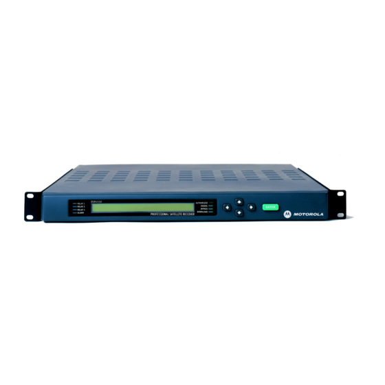
Powering On the DSR-4550 To apply power to the DSR-4550, perform the following steps: Plug the DSR-4550 into a power source and all LEDs on the front panel are illuminated while the front-panel LCD screen is blank. After approximately 60 seconds, the LEDs... - Page 21 Operating the DSR-4550 All operations described in this chapter require use of the DSR-4550 front panel, as shown in Figure 3-1. RELAY 1 RELAY 2 RELAY 3 ALARM Arrow Buttons LCD Screen Relay 1 Authorized ENTER Button Relay 2 Signal...
-
Page 22: Using The Front Panel
Using the Front Panel The front panel LCD screen displays a series of menus that can be used to configure and control the system. The name of the current menu is always in the upper left corner of the screen for easy identification. •... -
Page 23: Navigating The Menus
Operating the DSR-4550 Navigating the Menus Even though the keypad options shown on the LCD screen may change for each menu and for each field, the control buttons basically do the same thing. The user may want to practice on a screen to become familiar with how the buttons work. -
Page 24: How To Use The Menus
• Diagnostics menus, see page 55. The DSR-4550 allows the user to scroll only to menus that are in the same group. To scroll to a menu that is in a different menu group, return to the main top-level menu and select the desired menu group. -
Page 25: Overview Of The Lcd Panel Menu Tree
Operating the DSR-4550 Overview of the LCD Panel Menu Tree Pressing the ENTER button when the cursor is on a menu name causes the cursor to return to the main, top level menu. The charts on the following pages show the menus organized into five main groups: Installation menus, Channel selection menus, IP menus (including the GigE menus), Status menus, and Diagnostics menus. - Page 26 Channel Selection Menus CHANNEL VCT Chnl Xpndr 00000 0000 (Not in map) MPEG SELECT Program 00000 AUD1LANG Dspl Left Right InputMode AUD2LANG Dspl Left Right InputMode TEXT LANG Display EMM ID ID Number(Hex) 0000...
- Page 27 Operating the DSR-4550 Diagnostic Menus Status Menus STATUS1 FrontPanel Input Type DIAGNOSTIC Menus Local Control L-Band STATUS2 Source Channel Quality UNIT ADDRESS ---- 123-08000-12345-678 STATUS3 Signal_Quality TV PASS CARD Status ||||||||||||||||||......Not Inserted STATUS4 Freq Symb Code Format AUDIO TEST SIGNAL L1/R1...
-
Page 28: Installation Menus
Install Channel IP Status Diag Press the 4 buttons until the cursor is at the Install label, and press the ENTER button. The DSR-4550 displays the first sub-menu within the Installation menus. Manual Tune Menu Use this menu to initially acquire a DigiCipher II system signal and download virtual channel tables by selecting a transponder frequency for each of the eight L-Band inputs, which are labeled Port 1 through Port 8. - Page 29 Input Field Default: Port 1 Note: Unless changed, the DSR-4550 displays values for an L-band input on Port 1. The Input field displays the input to which the receiver is currently tuned. It allows manual selection of Port 1 through Port 8 for the L-band inputs or ASI input to the DSR-4550.
- Page 30 The DSR-4550 requires 30 to 60 seconds to download the network data. Afterward, the user can view the Port menu for the active port to select the satellite name from...
-
Page 31: Modulation Menu
DVB-MAN. Select a mode and press ENTER to exit the field. Note: In any of the non-auto modes [i.e., DCII-MAN, DVB-MAN (both manual modes) or 8PSK (Phase Shift Keying Modulation with turbocodes)], the DSR-4550 only searches for a signal that matches what is set in the Symbol/Code/Format field. -
Page 32: Port Menu
The user enters the satellite and polarity information directly when the port is setup manually. Otherwise, when the port is setup automatically, the DSR-4550 associates the port with the satellite and polarity information that matches the first virtual channel that is chosen (and acquired) after the user... - Page 33 Operating the DSR-4550 ID Field Default: 1 Use this field to choose which L-band port to configure. Press the 4 button until the cursor is at the ID field, then use the buttons to choose a port number (1-8). Press the ENTER button to select and exit the field.
-
Page 34: Port Config Menu
Default: Off Use this field to direct power to the external Low-Noise Block (LNB) converter. When the ON option is selected, the DSR-4550 supplies +20 VDC on the port 1 antenna input connector. Press the 4 button until the cursor is at the LNB Power label, and press the ENTER button to move into the field. - Page 35 Lang menu of the channel selection group), the DSR-4550 changes to Dual Mono, and uses the language previously selected for Mono (or Stereo) for both left and right. The DSR-4550 now requires e a language defined for both left and right dual mono outputs.
-
Page 36: Audio1 Gain And Audio2 Gain Menus
Audio1 Gain and Audio2 Gain Menus These menus allow adjustment of the audio signal output level from 0 to -20dB in 1dB increments. Press the buttons until the AUDIO1 GAIN or AUDIO2 GAIN menu appears. AUDIO1 GAIN Mode Left Right Joint AUDIO2 GAIN Mode... -
Page 37: Subcarrier Menu
ENTER button to confirm the selection. Alarm Menu This menu allows the user to set up different bypass modes in case the DSR-4550 goes into an alarm condition. Press the button until the Alarm menu is located (shown below). - Page 38 • The tuner loses lock when the input is RF. • The DSR-4550 cannot lock to the ASI input when the input is ASI. • The DSR-4550 is unable to render video. • The DSR-4550 is not authorized to access the selected service.
-
Page 39: Asi Output Menu
Default: Byte The Packet and Byte options specify the transport stream packet structure. When the ASI Output is enabled, the DSR-4550 outputs MPEG-2 transport stream packets, either as a burst of contiguous bytes (Packet option), or as individual bytes (Byte option). -
Page 40: Reset Menu
Power Cycle Option The Power Cycle option reboots the DSR-4550 without losing internal user setup information or downloaded network information. When the option is shown, press the ENTER button and a caution message appears indicating that the current service will be interrupted if the action proceeds. -
Page 41: Core Menu
Operating the DSR-4550 Press any arrow button ( 4 ) to back out of the field and leave it unchanged. Otherwise, press the ENTER button to proceed. The following message displays Power Cycle reset in progress. . . Press E to continue or... -
Page 42: Video Out Format Menu
Video Out Format Menu The Video Out Format menu allows the user to configure the video format. Press the buttons until the Video Out Format menu appears (shown below). It has two fields that allow modification of the output format. Note: The receiver does not convert 525-line video to 625-line video or convert 625-line video to 525-line video. -
Page 43: Aspect Ratio Menu
4x3 (Pan Scan) Input Field Read-only The Input field displays the aspect ratio of video that the DSR-4550 is currently receiving, either 4x3 or 16x9. This field is non-editable. Three dashes (---) are displayed when no signal is received. Output Field... -
Page 44: Digital Video/Audio Menu
The SDI field enables or disables the Serial Digital Interface (digital video output) from the one SDI connector on the rear of the DSR-4550. Press the buttons to enable or disable SDI and press the ENTER button to confirm the selection. -
Page 45: Firmware Menu
The Upgrade field displays the version of the upgrade code that is available. This field displays 000000 when no upgrade code is available. Available upgrades are installed the next time the DSR-4550 is powered on. This field is non-editable. Download Menu The Download menu allows the user to monitor the status of the current code download. -
Page 46: File Field
Current Field Read-only The Current field pertains to the file selected in the File field and indicates the ID for the current segment received by the DSR-4550 during the download of the file. This field is non-editable. Rcvd Field Read-only The Rcvd field indicates ID for the last segment of the file selected in the File field. -
Page 47: Channel Menus
Install Channel IP Status Diag Press the 4 buttons until the cursor is at the Channel label, and press the ENTER button to access the main menu for the Channel group and the DSR-4550 displays the first sub-menu within the Channel menus. -
Page 48: Chnl Field
Channels that exist in the Virtual Channel Map appear within parentheses, for example (346). The DSR-4550 supports channel values from 0000 to 9999. Press the 4 button until the cursor is at the Chnl label, and press the ENTER button to move into the field. -
Page 49: Xpndr Field
Note: The caution message shown on the previous page is only displayed when the user changes the channel from a valid virtual channel to a nonexistent virtual channel. This message is not displayed if the DSR-4550 was not already acquired to a virtual channel (e.g., when setting up the DSR-4550 for future operation). -
Page 50: Mpeg Select Menu
MPEG program number. Press the buttons until the MPEG SELECT menu appears. The MPEG program number can be used instead of a virtual channel, but only if the DSR-4550 is already tuned to the appropriate L-band or ASI input signal. -
Page 51: Aud1Lang, Aud2Lang Menus
Audio1 and Audio2 outputs. This menu also allows the user to view the mode of the audio signal as it is received from the programmer and before any subsequent down mixing that the DSR-4550 may perform. - Page 52 Left and Right Fields Default: Def Note: These fields operate in conjunction with the "Audio1 and Audio2 Menus" on page 24 (specifically the AudioMix field) and the Dspl (Display field) described on page 41. If the user selects the Dual Mono downmix in the AudioMix field within the "Audio1 and Audio2 Menus"...
-
Page 53: Inputmode Field
DSR-4550 selects and outputs the first occurrence of the Left language choice. The system cannot take a Left from one audio pair and a Right from another. If there is no match for the Left language choice, the DSR-4550 uses the default language setting. -
Page 54: Emm Id Menu
Press the 4 buttons until the cursor is at the Status label, and press the ENTER button. The DSR-4550 now displays the Status1 menu. Refer to "Status Display Menus" on page 50 for more information on each of the display screens. -
Page 55: Ip Menus
Read-only To view the MAC address for the lower Ethernet port on the back panel of the DSR-4550, press the buttons until the MAC Address menu appears (shown below). The address is represented in a hexadecimal format and non-editable. -
Page 56: Subnet Mask Menu
Use the following procedure to set and view the IP Gateway address (range: 000.000.000.000 to 255.255.255.255) for the lower Ethernet port on the back panel of the DSR-4550. The IP Gateway is an address that is represented in the common dotted-decimal format. Contact the network administrator for details about configuring the Ethernet port for operation on your local network. -
Page 57: Gige Menus
Read-only Use the following procedure to view the GigE MAC address for the upper Ethernet port on the back panel of the DSR-4550. The GigE MAC address is represented in a hexadecimal format and non-editable. Press the buttons until the Port GigE menu appears (shown below). -
Page 58: Gige Subnet Mask Menu
Use the following procedure to set and view the GigE Default Gateway address (range: 000.000.000.000 to 255.255.255.255) for the upper Ethernet port on the back panel of the DSR-4550. The GigE Default Gateway is an address that is represented in the common dotted-decimal format. Contact the network administrator for details about configuring the GigE port for operation on your local network. -
Page 59: Gige Mpts Address Menu
Operating the DSR-4550 GigE MPTS Address Menu Use the following procedure to set and view the GigE Multiple Program Transport Stream (MPTS) address and port of the destination node for the transport stream output. The GigE MPTS is an address that is represented in the common dotted- decimal format. -
Page 60: Status Display Menus
Install Channel IP Status Diag Press the 4 buttons until the cursor is at the Status label, and press the ENTER button. The DSR-4550 displays the first sub-menu within the Status menus. Status1 Menu Press the buttons until the Status1 menu appears (shown below). -
Page 61: Status2 Menu
Operating the DSR-4550 Status2 Menu Note: This menu is not displayed when the active signal is received from a source other than the L-band input connector. Press the buttons until the Status2 menu appears (shown below). This screen displays the source name, channel number, and the signal quality. -
Page 62: Status4 Menu
Status4 Menu Note: This menu is not displayed when the active signal is received from a source other than the L-band input connector. Press the buttons until the Status4 menu appears (shown below). This screen displays the satellite name and signal tuning characteristics and provides mode- specific information depending upon the acquisition mode selected (i.e., DCII- AUTO, DCII-MAN, DVB-MAN, etc.). -
Page 63: Status5 Menu
Operating the DSR-4550 Status5 Menu Note: This menu is not displayed when the active signal is received from a source other than the L-band input connector. Press the buttons until the Status5 menu appears (shown below). This screen displays the sync status, Eb/No (signal to noise ration) and authorization state of the DSR-4550. -
Page 64: Status6 Menu
Status6 Menu Press the buttons until the Status6 menu appears (shown below). This screen displays the DSR-4550’s Memory (free memory) and Flash memory. STATUS6 Memory Flash 42.9MB 47.8MB Memory Field Read-only This status-only field displays the amount of free volatile memory (range: 00.0 to 99.9 MB) that is available for use by the operating system. -
Page 65: Diagnostics Menus
Operating the DSR-4550 Diagnostics Menus The DSR-4550's diagnostic menus allow the user to isolate problems to the DSR- 4550 or the satellite using the front panel. The menus also enable the user to test waveforms and use other diagnostic information displayed on an NTSC television monitor connected through the rear-panel video output. -
Page 66: Clear Cntrs Field
000-12345-12345-678 TVPass Card Menu The DSR-4550 does not initially require a TV Pass Card, but if one is required, the program provider typically supplies one. The program provider uses the TV Pass Card address and decoder address to identify a specific DSR-4550 for authorization messages. -
Page 67: Audio Test Signal Menu
Operating the DSR-4550 Audio Test Signal Menu This menu allows the user to select an audio test signal for each of the two audio outputs, Audio1 and Audio2. Press the buttons until the Audio Test Signal menu appears (shown below). -
Page 68: Video Test Signal Menu
Press any arrow button ( 4 ) to back out of the field and leave it unchanged. Otherwise, press the ENTER button to proceed. Note: Test signals override any active service component, and the DSR-4550 displays diagnostics over the video test patterns if diagnostics are enabled. -
Page 69: Vits Menu
Operating the DSR-4550 VITS Menu This menu allows the user to insert VITS on lines 17 or 18. Press the buttons until the Vertical Interval Test Signal (VITS) menu appears (shown below). VITS Waveform Transmitted Waveform Field Default: Transmitted Note: Upon exiting this submenu, the Waveform field reverts to the default value (Transmitted). - Page 70 Field Field Default: 1 Note: The IRD does not display this field when the waveform is set to Transmitted or Disabled. The Field field allows the user to select the field on which the VITS is reinserted by the receiver. Press the 4 button until the cursor is at the Field label, and press the ENTER button to move into the field.
-
Page 71: Ad Insertion Test Menu
The Ad Insertion Test menu allows the user to turn cue tones and the relays on and off. Ad insertion signals are generated by the DSR-4550, but controlled by the uplink programmer. Local cable companies use ad insertion signals to control and to queue the insertion of commercials in cable headends. -
Page 73: Chapter 4 Troubleshooting
Contrast Field on page 31. No picture, no level No LNB signal port Connect LNB coax See "Connecting the indication DSR-4550" on page 5. Poor audio quality or low Audio levels Adjust audio levels See "Audio1 Gain and audio level incorrect Audio2 Gain Menus"... -
Page 75: Chapter 5 Downlink/L-Band Frequency Conversion Tables
Table 5-2: Calculation for Ku-Band Transponders (Using 12,019 MHz Downlink Frequency) Example calculation Formula for converting a Ku-band Frequency to an L-band Frequency if downlink frequency is 12,019 MHz Frequency Downlink (DL) <minus> 10,750 MHz <equals> Frequency (L-band) 12,019 MHz -10,750 MHz 1,269 MHz DSR-4550... -
Page 77: Chapter 6 Product Support
Product Support If You Need Help For assistance with Motorola Mobility products, contact Motorola Technical Support, 24 hours a day, 7 days a week. DSR-4550... -
Page 78: Calling For Repairs
Calling for Repairs If repair is necessary, call Motorola Mobility’s authorized repair vendor, World Wide Digital at 1-800-227-0450 or 1-956-541-0600 for shipping address and a Return for Service Authorization (RSA) number before sending the unit for repair. The RSA number must be prominently displayed on all equipment cartons and shipping label. -
Page 79: Chapter 7 Language Abbreviations
Egyptian Armenian English Balinese Esperanto Basque Faroese Batak (Indonesian) Finnish Bengali French Bhojpuri German Bulgarian Greek Burmese Gujarati Catalan Hebrew Chinese Hindi Croatian Hiri Motu Cue (Tones) Hungarian Czech Indonesian Danish Interlingua Dutch Iranian Irish Philippine (Other) Italian Polish DSR-4550... - Page 80 Language Abbreviation Language Abbreviation Panjabi Portuguese Japanese Rajasthani Javanese Romanian Kashmiri Russian Korean Samoan Kurdish Scots Latin Sindhi Malay Spanish Mandar Swahili Marathi Swedish Miscellaneous Tagalog Mongolian Tamil Nepali Thai Norwegian Urdu Otomian Lang. Vietnamese Pahlavi Welsh Persian...
-
Page 81: Chapter 8 Diagnostics
2. Decimal numbers are right-justified in their individual display rectangle and are not padded with leading zeros (0). 3. Decimal numbers may be displayed without or with a trailing decimal point to distinguish them from hexadecimal numbers. 4. The default is no trailing decimal point. DSR-4550... -
Page 82: Viewing The Fast Fact Diagnostic Screens
Viewing the Fast Fact Diagnostic Screens The diagnostic screens (Figure 8-1) are available via the On-Screen Display (OSD) video out using a video monitor connected to the OSD Video Out on the rear of the IRD. To view the OSD diagnostic screens, press the buttons on the front of the IRD until the Diagnostic menu appears, and press the ENTER button to access the Diagnostic menu on the IRD (shown below). -
Page 83: Fast Facts Screens
Symbol Rate = 10.51 Msps Frequency = 1310.000 MHz Field Name Definition Unit Factory-set, 16-digit Unit Address for the IRD. Shows the virtual channel number. Firmware Shows the firmware version in the boot sector of ROM and the application section. DSR-4550... - Page 84 Field Name Definition VCT ID Shows the current VCT ID. Encryption Displays the current program’s encryption status. Service Displays the service number for the current program. Auth State Displays the current program’s authorization status. Eb/No Shows the signal to noise ratio (Eb/No) of the received signal. Signal State Shows the received signal state, either Locked or Searching, depending on whether the IRD is locked to a signal or not.
-
Page 85: Fast Facts 2
Indicates the port is Inactive. Satellite Name The name of the current satellite. Polarization The polarity transponder associated with the port, either: Horz Horizontal Vert Vertical Configuration Status The configuration status of the port, either: Defined, Undefined or Not Supported. DSR-4550... -
Page 86: Fast Facts 3
Fast Facts 3 The Fast Facts 3 screen displays information relating to video information SDI = Enable Field Name Definition Video Locked An indication of video lock status, if Yes, then the video for the IRD is being received and locked. If No, then the video is not being received. - Page 87 FIFO Depth Count. Chroma Ratio The Chrominance format for the video within the transport stream. Video Rate The rate (in Mbps) of the video within the transport stream. Indicates whether or not the SDI input is enabled or disabled. DSR-4550...
-
Page 88: Fast Facts 4
Fast Facts 4 The Fast Facts 4 screen displays information relating to audio information. There are two columns of information displayed, one column for the first audio program, and the other column for the second audio program. AES = Enabled AES = Enabled Field Name... -
Page 89: Fast Facts 5 (10/100 Network)
Address Type The Address Type of the unit. MAC Address The MAC Address of the unit. IP Address The IP Address of the unit. Subnet Mask The Subnet Mask of the unit. Gateway The Gateway Address of the unit. DSR-4550... -
Page 90: Fast Facts 5 (Gigabit Ethernet)
Fast Facts 5 (Gigabit Ethernet) The Fast Facts 5 (Gigabit Ethernet) screen displays information relating to Gigabit Ethernet configuration Field Name Definition Network Status Provides the status of the GiGE Ethernet (e.g., Link Down, Half Duplex, Full Duplex, and Link Unknown). MAC Address MAC Address of the GiGE ethernet. -
Page 91: Chapter 9 Dsr-4550 Specifications
DSR-4550 Specifications Input Frequency Range 950 to 2150 MHz Input RF Level -25 to -65 dBm RF Port Impedance 75 Ohms RF Port Return Loss 8 dB minimum Port-to-Port Isolation 40 dB minimum Video (Analog) Frequency Response ±0.9 dB (1 kHz to 4.2 MHz) NTSC ±0.9 dB (1 kHz to 4.8 MHz) PAL... - Page 92 Video (SDI) Format SMPTE-259M Standard with embedded audio Channels 1/2 and Channels 3/4 Bit Rate 270 Mbps Signal Level 800 mV ± 10% Impedance 75 ohms ± 5% Output Jitter 740 picoseconds maximum Transmission Standard DCII Symbol Rates 3.25 to 29.27 Msps DCII Code Rates 5/11, 1/2, 3/5, 2/3, 3/4, 4/5, 5/6, and 7/8 Audio (Analog)
- Page 93 DSR-4550 Specifications Audio (Digital) Format AES (discrete), AES3, SMPTE-272, and SMPTE-291M (embedded) Outputs Right Channel, Left Channel Signal AES-3id (discrete), SMPTE-259M (embedded) Frequency Response 1.3 db p-p max, 20 Hz to 20 kHz Gain ± 1.0 dB (relative to 0 dB, 16 dBm in and 16.0 dB out @ 1 kHz)
- Page 94 Connectors (Continued) OSD Video Out BNC (Qty 1) GigE (Ethernet) RJ45 (Qty 1) 10/100 (Ethernet) RJ45 (Qty 1) Alarm Screw terminal (Qty 1) Cue Tone (Labeled: Q+ and Q-) Screw terminal (Qty 1) AUX Audio In Screw terminal (Qty 1) Audio Out (Primary and Secondary) Screw terminal (Qty 2) ISOC Data...
- Page 95 Si aucun système de collecte n'est disponible, veuillez appeler le Service clientèle de Motorola qui vous ménagères ou vos rebuts d'entreprise. système de collecte n'est disponible, veuillez appeler le Service clientèle de Motorola qui vous apportera son assistance.
- Page 98 PLEASE RECYCLE 6450 Sequence Dr. San Diego, CA 92121 Document No: 540038-001, Rev. F 540038- 001- 99...
Need help?
Do you have a question about the DSR-4550 and is the answer not in the manual?
Questions and answers