Table of Contents
Advertisement
Advertisement
Table of Contents

Related Manuals for Motorola DSR-4410


Summary of Contents for Motorola DSR-4410
- Page 1 DSR-4410 Commercial Integrated Receiver/ Decoder Operator Guide...
-
Page 2: Operation Precautions
Copyright © 2006-2008 Motorola, Inc. Warning: MOTOROLA and the Stylized M Logor are registered in the US Patent & Trademark Office. All other product or service names To prevent electrical shock, do not use the receiver electrical power are the property of their respective owners. - Page 3 DSR-4410 Integrated Commercial Receiver/Decoder Operator Guide...
-
Page 5: Table Of Contents
Chapter 1: Introducing the DSR4410................1 Key Features ..........................1 Chapter 2: Connecting the DSR4410................3 Unpacking And Connecting The DSR4410 ................3 Unpacking And Mounting ......................4 Connecting A Unit for L-Band Input..................4 Chapter 3: Operating the DSR4410 ................7 Using The Front Panel ...................... - Page 6 Vertical Interval Test Signal (VITS) Menu ................45 Ad Insertion Test Menu ......................46 Chapter 4: Troubleshooting ..................47 Chapter 5: Signal Flow ..................... 49 Chapter 6: Product Support ..................51 Product Support And Equipment Returns ................51 Product Support ........................51 IRD Repair Procedures ......................
-
Page 7: Chapter 1: Introducing The Dsr4410
• The user is able to select an input L-band frequency of 950 to 2150 MHz. The user can select a code rate from these values: 5/11, 1/2, 3/5, 2/3, 3/4, 4/5, 5/6, and 7/8. • Multiple Virtual Channel Tables (VCTs) can be stored in the DSR-4410 so that the unit can be tuned to various satellites/transponders. - Page 8 • One Form-C relay used for fault alarm indication • Memory to recall the operating configuration when power sags or is removed. ® • Security features include Motorola DigiCipher II security technology. The unit does ® not require a TVPass card to operate with security.
-
Page 9: Chapter 2: Connecting The Dsr4410
Connecting the DSR-4410 Unpacking And Connecting The DSR-4410 Cable connections described in this chapter are made to the rear panel of the DSR-4410. A C -1 2 0 V -2 5 0 V 5 0 /6 0 H z 5 0 w... -
Page 10: Unpacking And Mounting
Unpacking And Mounting The shipping carton contains the DSR-4410, two quick disconnect terminals, a power cord and this Operator Guide. The IRD should be installed in an Electronics Industry Association (EIA) compliant 19- inch rack. It is recommended that the IRDs have 1RU spacing, above and below, for airflow. - Page 11 (L+ and L-) to the audio inputs on the channel modulator. Right Audio Out terminals (R+ and R-) will also contain the single mono. The DSR-4410 will be able to generate cue tones when commanded over the satellite link. If these internally generated cue tones are used, connect the 600 ohm differential Cue...
-
Page 13: Chapter 3: Operating The Dsr4410
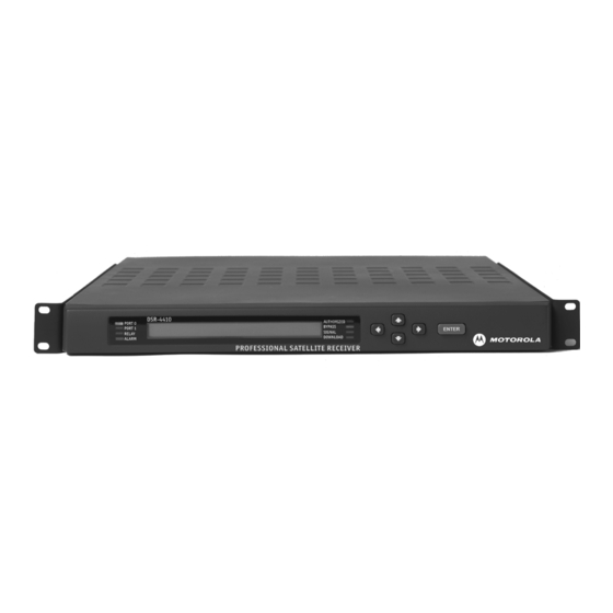
All operations described in this chapter require use of the front panel. As illustrated in Figure 3-1, the front panel has an operator's keypad and several LEDs used as indicator lights. Figure 3-1 DSR-4410 Front Panel 1. Port 0 LED 6. -
Page 14: Using The Front Panel
Using The Front Panel The front panel LCD screen displays a series of menus that can be used to configure and control the system. The name of the current menu is always in the upper left corner of the screen for easy identification. •... - Page 15 Operating the DSR-4410 • Pressing the56buttons while the cursor is blinking next to the menu name (far left corner), will scroll to another menu. • Pressing the Enter button while the cursor is blinking next to the menu name (far left corner) will scroll to the Main, top-level menu.
- Page 17 Operating the DSR-4410 DSR-4410...
-
Page 19: How To Use The Menus
About Menu The front panel LCD will display the About menu when the unit is plugged in or after factory reset. This menu identifies the unit model (“MOTOROLA DSR-4410”) and the software version that is currently installed. This menu is displayed for only 30 seconds, after which the front panel LCD will display the Main menu. -
Page 20: Manual Tune Menu
If, however, selection of an International C-band, a functional transponder, or a Ku-band satellite is preferred, use the L Freq option in the Mode field and directly enter the L-band frequency. The DSR-4410 requires no distinction between Ku-band and C-band signals after selecting the L-band carrier frequency. - Page 21 Operating the DSR-4410 The following Caution screen will appear, asking the user to confirm the selection. If you press any3456 button at this point, the Caution screen will disappear and the ManualTune menu will reappear without any changes. But, to make a selection, press the Enter button to set the port selection.
-
Page 22: Modulation Menu
transponder options, and when the transponder selection is displayed, press the Enter button to confirm selection and move the cursor back up to the field label. This field is not available when the ASI In option in the Input field is selected. LFreq Field (for Custom Plans) This field allows the user to directly tune the frequency, if the L Freq option in the Mode field is chosen. -
Page 23: Port0 Setup And Port1 Setup Menus
Operating the DSR-4410 When the DCII-Man option in the Mode field is selected the user must additionally specify a Symbol/Code/Format combination. This menu is not available when the ASI In option is chosen. That option is located in the Manual Tune menu. - Page 24 Port0 and Port1 may be setup manually or automatically, and each individually. The user enters the satellite and polarity information directly when the port is setup manually. Otherwise, when the port is setup automatically, the unit associates the port with the satellite and polarity information that matches the first virtual channel that is chosen (and acquired) after the user manually tunes that port (refer to the Manual Tune Menu section).
-
Page 25: Audio 1 And 2 Menus
Operating the DSR-4410 This field is not editable when the Auto option in the Mode field is selected. This field displays the polarity to which the port is related. This field will display the default when the port is not related to a satellite. The defaults for Port0 and Port1 are H/LHP and V/RHP, respectively. -
Page 26: Audio1 Gain And Audio2 Gain Menus
changed to Dual Mono output. The unit will now seek to have a language defined for both left and right dual mono outputs. • By pressing the Enter button (ignoring the caution and taking no action in the Lang menu of the channel selection group), the unit will change to Dual Mono, and it will use the language previously selected for Mono (or Stereo) for both left and right. -
Page 27: Alarm Menu
Operating the DSR-4410 Mode Field The Mode field allows the user to select the mode by which the user adjusts the Audio Gain port. Press the4button until the cursor is at the Mode label, and press the Enter button to move into the field. Press the56buttons to view the desired mode. There are two options, Independent and Joint. -
Page 28: Asi Output Menu
There are five choices: Disabled, Auto, No Signal, No Video, No Auth (Authorization). Use this option to select which of the above conditions activates the alarm. The default setting is Auto. Bypass Field Press the4button until the cursor is at the Bypass label, and press the Enter button to move into the field. -
Page 29: Reset Menu
Operating the DSR-4410 to EN 50083-9, “Cabled distribution systems for television, sound, and interactive multimedia signals; Part 9: Interfaces for CATV/SMATV headends and similar professional equipment for DVB/MPEG-2 transport streams.” PID Alias Field Press the4button until the cursor is at the PID Alias label, and press the Enter button to move into the field. -
Page 30: Mac Address Menu
Press a directional (3456) button to back out of the field and leave it unchanged. Otherwise, press the Enter button to proceed. The following message will appear. Power Cycle Option The Power Cycle option will reboot the unit without losing internal user setup information or downloaded network information. -
Page 31: Subnet Mask Menu
Operating the DSR-4410 decimal format. Contact the network administrator for details about configuring the Ethernet port for operation on your local network. Press the4button until the cursor is at the Address label, and press the Enter button to move into the field. Press the34and 56buttons to enter the desired address and then press Enter to confirm the selection. -
Page 32: Core Menu
Core Menu Press the 56 buttons until the Core menu appears. This menu allows the user to change the front panel LCD contrast, select where text (e.g., subtitles) is displayed, and turn on/off the LNB power output. Contrast Field To adjust the LCD contrast, press the4button until the cursor is at the Contrast label, and press the Enter button to move into the field. - Page 33 Operating the DSR-4410 encoder is a 625-line, the field selects the type of PAL the receiver outputs, and the NTSC or PAL M selection has no impact. 525 Lines Field Press the4button until the cursor is at the 525 Lines label, and press the Enter button to move into the field.
-
Page 34: Firmware Menu
The output default setting is 4x3 PAN. If 4x3 PAN information is not available when the 4x3 PAN option is chosen, the unit will output the center portion of the 16x9 image. If you select a new aspect ratio a warning screen will appear. Press a directional (3456) button to back out of the field and leave it unchanged. -
Page 35: Download Menu
Operating the DSR-4410 Download Menu Press the56buttons until the Download menu appears. This menu allows the user to monitor the status of the current code download. This menu is used most commonly in troubleshooting. During a background code download the unit collects the upgrade code in the background while concurrently decoding video and audio services. - Page 37 Operating the DSR-4410 Channel Menus: Group 2 Channel Menu Press the56buttons until the Channel menu appears. This menu allows the user to select an active VCT, select the virtual channel, and view the name of the current transponder. The DigiCipher II system allows for retune events in which a programmer sends over-the-satellite messages to specified receivers to change the service they output for a specified time period, then return to a specified service.
- Page 38 This field also provides a second method for selecting the virtual channel: Use the34buttons to select the digit to change and then, while the cursor is on that digit, press the56buttons to display the required value. Repeat for each applicable digit. The unit displays warning messages for the following conditions.
-
Page 39: Mpeg Select Menu
Operating the DSR-4410 Press a directional (3456) button to back out of the field and leave it unchanged. The unit will not be able to decode the chosen virtual channel until a port is setup with the applicable satellite and polarity information. - Page 40 The unit displays warning messages for the following conditions. • A warning message is displayed when the user changes from a virtual channel to a MPEG program number.Press a directional (3456) button to back out of the field and leave it unchanged. Otherwise, press the Enter button to proceed. •...
- Page 41 Operating the DSR-4410 displayed in the Left (channel) and Right (channel) fields. There are three options: All, Avail, and Status. Press the56buttons to display the options. The All option allows the user to scroll throughout the languages that exist in the database while in the Left and Right fields.
-
Page 42: Text Lang(Uage) Menu
• There is an interaction between the Language (Lang) menu and the AudioMix field of the Audio menu (installation menu group): • If the user had previously selected Stereo or Mono in the AudioMix field and a specific language as the audio output in the Lang menu, but later changes the AudioMix menu setting to Dual Mono, the Dual Mono will change in this menu to the same language specified for both Dual Mono channels. -
Page 43: Emm Id Menu
Operating the DSR-4410 Entitlement Management Message ID (EMM ID) Menu The Entitlement Management Message (EMM) ID menu allows for additional flexibility in access control. It allows the user to enter a new EMM provider ID number if provided by the programmer. -
Page 44: Status1 Menu
Status Display Menus: Group 3 Status display menus provide information regarding the current status of the unit. They group together important parameters and display them conveniently together for the user to review the receiver's operation. These fields are not editable, and the displayed information is either (1) the result of changes in an installation or channel selection menu, or (2) a parameter the unit reports as part of its operation. -
Page 45: Status3 Menu
Operating the DSR-4410 Channel Field The Channel field displays the selected virtual channel number (from the Channel menu). Dashes are displayed when no information is available. Quality Field The Quality field displays a number from 1 to 100 so that the quality level of the signal can be judged. -
Page 46: Status5 Menu
Symbol (Symb) Field This field displays the symbol rate (megasymbols per second) of the L-band signal. Dashes are displayed when no information is available or when the ASI input is in use. Code Field This field displays the code rate (error control coding for forward error correction) of the L-band signal. - Page 47 Operating the DSR-4410 Diagnostics Menus: Group 4 The unit's diagnostic menus allow the user to isolate problems to the unit or the satellite using the front panel. They also enable the user to test waveforms and use other diagnostic information displayed on an NTSC television monitor connected through the rear panel video output.
-
Page 48: Audiotestsignal Menu
Unit Address Menu Press the56buttons until the Unit Address menu appears. This menu is for display only, and it shows the unit address. The Unit Address menu displays the decoder’s electronic address in decimal digits. The program provider uses this address to identify a specific unit for authorization and to retune messages. -
Page 49: Video Test Signal Menu
Operating the DSR-4410 Caution: Audio output to the customers may be interrupted. In order to terminate an audio test signal, scroll to OFF or exit the L1/R1 field. L2/R2 Field This field allows the user to enable the Audio 2 test signal. Refer to the description for the L1/R1 field. -
Page 50: Vertical Interval Test Signal (Vits) Menu
Press a directional (3456) button to back out of the field and leave it unchanged. Otherwise, press the Enter button to proceed. Test signals override any active service component, and the unit displays diagnostics over the video test patterns if diagnostics are enabled. Disable the selected signals by displaying Off or exiting the menu. -
Page 51: Ad Insertion Test Menu
Operating the DSR-4410 The default waveform is “Transmitted” (indicating whatever signal is provided over the satellite link by the programmer, if one is present). Press the Enter button to confirm the selection. Notice that if the Waveform option is neither Transmitted or Disabled, the Field and Line fields will appear on the Vertical Interval Test Signal menu. - Page 52 Cue Tone Signal (Cue Tone Sig) Field The Cue Tone Sig (Signal) field lets the user turn the cue tone test on and off. Press the4button until the cursor is at the Cue Tone Sig label, and press the Enter button to move into the field.
-
Page 53: Chapter 4: Troubleshooting
No audio or Bypass Audio is Unit set in bypass mode Change to channel available present Will not acquire Port not configured Check port configuration; check manual frequency tune Incorrect language Wrong language setting Check language screen settings DSR-4410... -
Page 55: Chapter 5: Signal Flow
Signal Flow DSR-4410... - Page 56 Signal Flow DSR4410...
-
Page 57: Chapter 6: Product Support
Product Support If You Need Help For assistance with Motorola products only, contact the Motorola Technical Response Center (TRC), 24 hours a day, 7 days a week: • Inside the U.S.: 1-888-944-HELP (1-888-944-4357) • Outside the U.S.: 1-215-323-0044 • Motorola Online: http://businessonline.motorola.com This offers a searchable solutions database, technical documentation, and low-priority issue creation and tracking. - Page 58 Label all cartons with the RSA number. Ship the unit PREPAID to: World Wide Digital c/o Loera Customs Brokerage, Inc. Attn: RSA # **** 5845 E. 14th Street, Suite D Brownsville, TX 78521...
-
Page 59: Chapter 7: Conversion Tables
-Downlink frequency (MHz) -3,740 MHz L-band frequency (MHz) 1,410 MHz Calculation for Ku-Band Transponders Example calculation if downlink Formula for Ku-band frequency: frequency = 12,019 MHz: Downlink frequency (MHz) 12,019 MHz -10,750 (MHz) -10,750 MHz L-band frequency (MHz) 1,269 MHz DSR-4410... -
Page 61: Chapter 8: Language Abbreviations
Refer to Language Menu operation. LANGUAGE ABBREVIATION LANGUAGE ABBREVIATION Arabic Japanese Armenian Javanese Balinese Kashmiri Basque Korean Batak (Indonesian) Kurdish Bengali Latin Bhojpuri Malay Bulgarian Mandar Burmese Marathi Catalan Miscellaneous Lang. Chinese Mongolian Croatian Nepali Cue (Tones) Norwegian Czech Otomian Lang. Danish Pahlavi DSR-4410... - Page 62 LANGUAGE ABBREVIATION LANGUAGE ABBREVIATION Dutch Persian Egyptian Philippine (Other) English Polish Esperanto Portuguese Faroese Rajasthani Finnish Romanian French Russian German Samoan Greek Scots Gujarati Sindhi Hebrew Spanish Hindi Swahili Hiri Motu Swedish Hungarian Tagalog Indonesian Tamil Interlingua Thai Iranian Urdu Irish Vietnamese Italian...
- Page 63 DSR-4410 Specifications Table 9-1 Input Frequency Range 950-2150 MHz Input RF Level -25 to -65 dBm RF Port Impedance 75 Ohms RF Port Return Loss 8 dB minimum Port-to-Port Isolation 40 dB minimum Table 9-2 VIDEO Frequency response ±0.9 dB (1 kHz to 4.2 MHz) NTSC ±0.9 dB (1 kHz to 4.8 MHz) PAL...
- Page 64 Table 9-2 VIDEO Differential Phase 4.5% p-p maximum (10% to 90% APL) Table 9-3 TRANSMISSION STANDARD DCII Symbol Rates 3.25-29.27 Msps DCII Code Rates 5/11, 1/2, 3/5, 2/3, 3/4, 4/5, 5/6, 7/8 DVB Symbol Rates 3.25-30 Msps DVB Code Rates 1/2, 2/3, 3/4, 4/5, 7/8 Table 9-4 AUDIO...
-
Page 65: Chapter 9: Dsr4410 Specifications
DSR-4410 Specifications Table 9-5 ELECTRICAL LNB Power Supply 19-21 V minimum, 480 mA loaded Connectors RF in F-type Video in/out QTone Screw terminal Audio in/out Screw terminal ISOC data Screw terminal Contact Closure Screw terminal BNC connector Table 9-6 MECHANICAL Dimensions H 3.1"... - Page 68 Motorola Broadband Communications Sector 6450 Sequence Dr. San Diego, CA 92121 Publication #495018-001 Rev. D...
Need help?
Do you have a question about the DSR-4410 and is the answer not in the manual?
Questions and answers