
Related Manuals for AERMEC VXT


Summary of Contents for AERMEC VXT
- Page 1 Pompa di calore condensata ad acqua Pompa di calore condensata ad acqua Electronic adjustment for water-cooled heat pumps MANUALE USO • USAGE MANUAL IVXTUI. 0907 - 4900563_00...
- Page 2 I-37040 Bevilacqua (VR) Italia – Via Roma, 44 Tel. (+39) 0442 633111 Telefax 0442 93730 – (+39) 0442 93566 www .aermec. com - info @ aermec. com NUMERO DI SERIE DICHIARAZIONE DI CONFORMITÀ Noi, firmatari della presente, dichiariamo sotto la nostra esclusiva responsabilità che l'insieme in oggetto così...
-
Page 3: Table Of Contents
Indice Caratteristiche della regolazione ..................4 Interfaccia utente ........................ 4 Note sulla procedura guidata primo avviamento ............5 Procedura configurazione guidata ................... 5 Struttura e navigazione menù ..................11 Utilizzo dei tasti, visualizzazioni e parametri ..............12 Operazioni di navigazione e modifica parametri ............13 Parametri MENÚ... -
Page 4: Caratteristiche Della Regolazione
Caratteristiche della regolazione Il pannello comandi dell’unità permette parametri impostati e degli eventuali gnimento, l’impostazione del modo una rapida impostazione dei parametri allarmi intervenuti. Nella scheda ven- di funzionamento (freddo-caldo), e la di funzionamento della macchina e la gono memorizzate tutte le impostazioni visualizzazione del riassunto allarmi. -
Page 5: Note Sulla Procedura Guidata Primo Avviamento
è necessario conoscere l’impianto (tipologia, com- ponenti installati, ecc...) in cui è stata installata l’unità. ATTENZIONE: Le unità VXT prevedono un’autoconfigurazione in base alle caratteristiche dell’impianto nel quale è inserito; tale configurazio- ne deve essere eseguita da personale competente, seguendo le indica- zioni fornite di seguito. - Page 6 Selezione tipologia di circuito al condensatore (geo- termia o acqua di pozzo) L'unita e': 1.Geoter.20% Glicol • Premere il tasto B; 2.Geoter.10% Glicol • Tenere premuto il tasto C o A per impostare la scelta; 3.Pozzo • Premere il tasto B per confermare; •...
- Page 7 Selezione presenza/assenza del kit freecooling (accessorio) L'unita ha l'acces_ • Premere il tasto B; sorio Freecooling? • Tenere premuto il tasto C o A per impostare la scelta; • Premere il tasto B per confermare; • Premere il tasto C per passare alla finestra successiva; Selezione presenza/assenza di una fonte di integra- zione L'unita ha fonte...
- Page 8 Selezione gestione valvole miscelatrici L'unita con_ • Premere il tasto B; trolla miscelatrici? • Tenere premuto il tasto C o A per impostare la scelta; • Premere il tasto B per confermare; • Premere il tasto C per passare alla finestra successiva; Selezione gestione pompe di ricircolo La Pdc controlla •...
- Page 9 Abilitare/Disabilitare On-Off da contatto digitale Le operazioni da eseguire sono: Vuoi abilitare • Premere il tasto B; L'on-off della Pdc • Tenere premuto il tasto C o A per impostare la scelta; da contatto digitale • Premere il tasto B per confermare; •...
- Page 10 Selezione protocollo per BMS Le operazioni da eseguire sono: Per il sistema • Premere il tasto B; BMS utilizzi: • Tenere premuto il tasto C o A per impostare la scelta; 1.RS485 modbus • Premere il tasto B per confermare; •...
-
Page 11: Struttura E Navigazione Menù
La navigazione nei vari menù per la ge- no per un indice specifi co indicato dalla del menù set-point (caratterizati dall’in- stione delle unità VXT, è rappresentata lettera P, e un numero progressivo che dice S); dallo schema proposto in alto; in tale indica in maniera univoca la pagina (per 5 - Rappresenta l’insieme dei parametri... -
Page 12: Utilizzo Dei Tasti, Visualizzazioni E Parametri
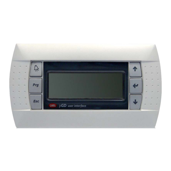
Utilizzo dei tasti, visualizzazioni e parametri L’interfaccia utente principale è rappre- è spiegata nella pagina sucessiva), il destro del pannello; tali tasti vengono sentata da un display grafi co (120x32 default nella visualizzazione di questi utilizzati anche per la modifi ca dei para- pixel) con sei tasti per la navigazione;... -
Page 13: Operazioni Di Navigazione E Modifica Parametri
Operazioni di navigazione e modifica parametri Pagina selezione MENÚ: Passare ad un altro menù Per passare da un menù ad un altro è necessario attivare la schermata di selezione menù; tale visualizzazione è attivabile tra- mite la pressione del tasto , o del tasto Nota: se si stà... -
Page 14: Parametri Menú Principale
Parametri MENÚ PRINCIPALE Menù PRINCIPALE - PAGINA 0 Visualizzazione sul diplay dell’unità Indice Visualizzazione/Parametro Data e ora: questi dati vengono visualizzati solo su questa finestra (finestra di default all’accensione dell’unità, o durante il normale funzionamento). Indice pagina: Identifica il menù e la pagina corrispondente: P = Menù... - Page 15 Menù PRINCIPALE - PAGINA 7 Visualizzazione sul diplay dell’unità Indice Visualizzazione/Parametro Chiamata: Indica la richiesta di lavoro che la macchina stà attualmente soddisfando: • Estate (richiesta freddo) • Inverno (richiesta caldo) • Attesa (attesa di richiesta lavoro) • Sanitario (richiesta acqua calda sanitaria) •...
- Page 16 Menù PRINCIPALE - PAGINA 10 Visualizzazione sul diplay dell’unità Indice Visualizzazione/Parametro Compressore 1 ON: Indica se il compressore 1 è in funzione; ovvero se l’unità stà lavorando per soddisfare una chiamata. C o m p r e s s o r e 1 O n P 1 0 Indice pagina: Identifica il menù...
- Page 17 Menù PRINCIPALE - PAGINA 13 Visualizzazione sul diplay dell’unità Indice Visualizzazione/Parametro Sonde di temperatura per aria esterna e geotermia: Indica le temperature dell’aria esterna, e dell’ingresso condensatore (la quale può indicare la temperatura acqua sonda geotermica, oppure temperatura acqua di falda, in base al tipo di impianto previsto).
-
Page 18: Parametri Menú Set-Point
Menù PRINCIPALE - PAGINA 26 Visualizzazione sul diplay dell’unità Indice Visualizzazione/Parametro Visualizzazione ore di funzionamento: In questa pagina viene visualizzato il numero di ore di funzionamento della pompa di calore Indice pagina: Identifica il menù e la pagina corrispondente: P = Menù PRINCIPALE S = Menù... - Page 19 Menù SET-POINT - PAGINA 1 Visualizzazione sul diplay dell’unità Indice Visualizzazione/Parametro Indice pagina: Identifica il menù e la pagina corrispondente: P = Menù PRINCIPALE S = Menù SET POINT M = Menù MANUTENTORE (Bloccato) C = Menù COSTRUTTORE (Bloccato) S e t p o i n t CK = Menù...
-
Page 20: Parametri Menú Orologio
Parametri MENÚ OROLOGIO Menù OROLOGIO - PAGINA 1 Visualizzazione sul diplay dell’unità Indice Visualizzazione/Parametro Set orologio: In questa pagina è possibile impostare l’orologio interno alla scheda di regolazione. Indice pagina: Identifica il menù e la pagina corrispondente: P = Menù PRINCIPALE S = Menù... - Page 21 Menù OROLOGIO - PAGINA 3 Visualizzazione sul diplay dell’unità Indice Visualizzazione/Parametro Set fascie orarie: In questa pagina è possibile impostare le fascie orarie settimanali (Sabato e Domenica) per la zona 1. Indice pagina: Identifica il menù e la pagina corrispondente: P = Menù...
- Page 22 Menù OROLOGIO - PAGINA 5 Visualizzazione sul diplay dell’unità Indice Visualizzazione/Parametro Set fascie orarie: In questa pagina è possibile impostare le fascie orarie settimanali (Sabato e Domenica) per la zona 2. Indice pagina: Identifica il menù e la pagina corrispondente: P = Menù...
- Page 23 Menù OROLOGIO - PAGINA 5 Visualizzazione sul diplay dell’unità Indice Visualizzazione/Parametro Set fascie orarie: In questa pagina è possibile impostare le fascie orarie settimanali (Sabato e Domenica) per la zona 7. Indice pagina: Identifica il menù e la pagina corrispondente: P = Menù...
-
Page 24: Tabella Riassuntiva Allarmi
Tabella riassuntiva allarmi possibili errori che l’unità può generare, matica, o in maniera manuale (in base Le unità prevedono la segnalazione e una breve spiegazione delle possibili alla tipologia e alla gravità dell’allarme dei possibili malfunzionamenti dell’uni- cause. tà; tali segnalazioni vengono indicate accorso);... - Page 25 I-37040 Bevilacqua (VR) Italia – Via Roma, 44 Tel. (+39) 0442 633111 Telefax 0442 93730 – (+39) 0442 93566 www .aermec. com - info @ aermec. com SERIAL NUMBER EC DECLARATION OF CONFORMITY We, the undersigned, hereby declare under our own responsibility that the assembly in...
- Page 26 Index Regulation features ......................27 User interface ........................27 Notes regarding the guided commissioning procedure ..........28 Guided configuration procedure ..................28 Menu structure and navigation ..................34 Using the keys, displays and parameters ..............35 Navigation and parameters modification operations ..........36 MAIN MENU parameters ....................
-
Page 27: User Interface
Regulation features The unit control panel allows quick set- and any alarms that have intervened. All functioning mode (cooling-heating) and ting of the machine functioning para- default settings and any modifi cations display of the alarms summary. After a meters and their display. The display is are memorised in the board. -
Page 28: Notes Regarding The Guided Commissioning Procedure
(type, components installed etc...) in which the unit has been installed. ATTENTION: The VXT units envision self-configuration on the basis of the system features in which it has been inserted. This configuration must be performed by skilled staff, following the indications supplied below. - Page 29 Selecting the type of circuit to the condenser (geo- thermy or well water) The unit is: The following operations must be performed: 1.Geother.20% Glyc • Press key B; 2.Geother.10% Glyc • Hold down key C or A to set the selection; 3.Well water •...
- Page 30 Selecting presence/absence of the freecooling kit (accessory) The following operations must be performed: The unit has the ac_ • Press key B; cesory Freecooling? • Hold down key C or A to set the selection; • Press key B to confirm; •...
- Page 31 Selecting mixer valve management The following operations must be performed: The unit • Press key B; handles mixing? • Hold down key C or A to set the selection; • Press key B to confirm; • Press key C to pass to the next window; Selecting recirculation pump management The following operations must be performed: The heat pump...
- Page 32 Enabling/Disabling On-Off from digital contact The following operations must be performed: • Press key B; Enable On-Off • Hold down key C or A to set the selection; Digital input • Press key B to confirm; • Press key C to pass to the next window; Selecting the function assigned top the programma- ble output Config.
- Page 33 Selecting protocol for BMS The following operations must be performed: Address pdc • Press key B; for BMS: • Hold down key C or A to set the selection; 1.RS485 modbus • Press key B to confirm; • Press key C to pass to the next window; 2.Pcoweb Selecting address for BMS The following operations must be performed:...
-
Page 34: Menu Structure And Navigation
The navigation in the various menus for fi ed by a specifi c index indicated by of the set-point menu (characterised by the management of the VXT unit is re- the letter P and a progressive number the index S);... -
Page 35: Using The Keys, Displays And Parameters
Using the keys, displays and parameters The main user interface is represented plained in the next page). The default for These keys are also used to modify the by a graphic display (120x32 pixel) with displaying these menus is represented parameters selected, according to the six keys for navigation. -
Page 36: Navigation And Parameters Modification Operations
Navigation and parameters modification operations MENU selection page: Pass to another menu Setpoint To pass from one menu to another, it is necessary to activate the menu selection screen. This display can be activated by pres- Maintainer sing , or Manufactory Note: if the menu selection screen is being displayed, another press of the ESC key will take the user back to the 0 page of the... -
Page 37: Main Menu Parameters
MAIN MENU parameters MAIN menu - PAGE 0 Visualisation on unit display Index Display/Parameter Date and time: this data are only displayed in this window (default window on unit switch-on or during normal functio- ning). Page index: Identifies the menu and the corresponding page: P = MAIN menu S = SET-POINT menu M = MAINTENANCE TECHNICIAN menu (Blocked) - Page 38 MAIN menu - PAGE 7 Visualisation on unit display Index Display/Parameter Call: Indicates the work request that the machine is currently satisfying: • Summer (cooling request) • Winter (heating request) • Stand-by (stand-by for work request) • DHW (request for DHW) •...
- Page 39 MAIN menu - PAGE 10 Visualisation on unit display Index Display/Parameter Compressor 1 ON: Indicates whether compressor 1 is wor- king, i.e. if the unit is working to satisfy a call. C o m p r e s s o r 1 O n P 1 0 Page index: Identifies the menu and the corresponding page: P = MAIN menu...
- Page 40 MAIN menu - PAGE 13 Visualisation on unit display Index Display/Parameter Temperature probes for external air and geothermy: Indicates the temperatures of the external air and the con- denser inlet (which can indicate the geothermy probe water temperature or the water sheet temperature, on the basis of the type of system envisioned).
-
Page 41: Set-Point Menu Parameters
MAIN menu - PAGE 26 Visualisation on unit display Index Display/Parameter Functioning hours display: This page displays the number of functioning hours of the heat pump. Page index: Identifies the menu and the corresponding page: P = MAIN menu S = SET-POINT menu M = MAINTENANCE TECHNICIAN menu (Blocked) C = MANUFACTURER’S menu (Blocked) R u n n i g H o u r s... - Page 42 SET POINT menu - PAGE 1 Visualisation on unit display Index Display/Parameter Page index: Identifies the menu and the corresponding page: P = MAIN menu S = SET-POINT menu M = MAINTENANCE TECHNICIAN menu (Blocked) C = MANUFACTURER’S menu (Blocked) S e t p o i n t CK = CLOCK menu C o o l i n g...
-
Page 43: Clock Menu Parameters
CLOCK MENU parameters CLOCK menu - PAGE 1 Visualisation on unit display Index Display/Parameter Set clock: In this page it is possible to set the clock inside the regulation board. Page index: Identifies the menu and the corresponding page: P = MAIN menu S = SET-POINT menu M = MAINTENANCE TECHNICIAN menu (Blocked) C = MANUFACTURER’S menu (Blocked) - Page 44 CLOCK menu - PAGE 3 Visualisation on unit display Index Display/Parameter Set time periods: In this page it is possible to set the weekly time periods (Saturday and Sunday) for area 1. Page index: Identifies the menu and the corresponding page: P = MAIN menu S = SET-POINT menu M = MAINTENANCE TECHNICIAN menu (Blocked)
- Page 45 CLOCK menu - PAGE 5 Visualisation on unit display Index Display/Parameter Set time periods: In this page it is possible to set the weekly time periods (Saturday and Sunday) for area 2. Page index: Identifies the menu and the corresponding page: P = MAIN menu S = SET-POINT menu M = MAINTENANCE TECHNICIAN menu (Blocked)
- Page 46 CLOCK menu - PAGE 7 Visualisation on unit display Index Display/Parameter Set time periods: In this page it is possible to set the weekly time periods (Saturday and Sunday) for area 7. Page index: Identifies the menu and the corresponding page: P = MAIN menu S = SET-POINT menu M = MAINTENANCE TECHNICIAN menu (Blocked)
-
Page 47: Alarms Summary Table
Alarms summary table and a brief explanation of the possible basis of the type and seriousness of the The units envision the signalling of the causes. alarm that has occurred). To reset the possible unit malfunctions. These si- Also remember that the possibility exists gnals are indicated by the fl... - Page 48 AERMEC S.p.A. si riserva la facoltà di apportare in qualsiasi momento tutte le modifiche ritenute necessarie per il miglioramento del prodotto. Les données mentionnées dans ce manuel ne constituent aucun engagement de notre part. Aermec S.p.A. se réserve le droit de modifier à tous moments les données considérées nécessaires à...
Need help?
Do you have a question about the VXT and is the answer not in the manual?
Questions and answers