JVC GY-HM790CHU Instructions Manual
Hd memory card camera recorder
Hide thumbs
Also See for GY-HM790CHU:
- Connection instruction (1 page) ,
- Instructions manual (144 pages) ,
- Service manual (31 pages)
Table of Contents
Advertisement
Quick Links
Download this manual
See also:
Service Manual
HD MEMORY CARD CAMERA RECORDER
GY-HM790U
GY-HM790CHU
GY-HM790E
GY-HM790CHE
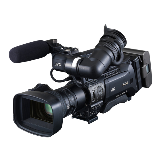
* The illustration shows the GY-HM790E with the supplied viewfinder, microphone and lens attached.
* GY-HM790CHU/GY-HM790CHE does not come with a lens.
For Customer Use:
Enter below the Serial No. which is located on the body.
Retain this information for future reference.
Model No.
GY-HM790U/GY-HM790CHU
Serial No.
INSTRUCTIONS
Please read the following before getting started:
Thank you for purchasing this JVC product.
Before operating this unit, please read the instructions
carefully to ensure the best possible performance.
In this manual, each model number is described without the last letter
(U/E) which means the shipping destination. (U: for USA and Canada,
E: for Europe)
Only "U"models (GY-HM790CHU/GY-HM790U) have been evaluated by
UL.
LST1108-001A
Advertisement
Table of Contents

Related Manuals for JVC GY-HM790CHU


Summary of Contents for JVC GY-HM790CHU
- Page 1 GY-HM790E GY-HM790CHE * The illustration shows the GY-HM790E with the supplied viewfinder, microphone and lens attached. * GY-HM790CHU/GY-HM790CHE does not come with a lens. For Customer Use: Enter below the Serial No. which is located on the body. Retain this information for future reference.
-
Page 2: Important Safeguards
Introduction FOR USA These are general IMPORTANT SAFEGUARDS and certain items may not apply to all appliances. Read all of these instructions. Save these instructions for later use. All warnings on the product and in the operating instructions should be adhered to. Unplug this appliance system from the wall outlet before cleaning. -
Page 3: Safety Precautions
CAUTION: CHANGES OR MODIFICAT IONS NOT APPROVED BY JVC COULD VOID USER’S AUTHORITY TO OPERATE THE EQUIPMENT. THIS DEVICE COMPLIES WITH PART 15 OF THE FCC RULES. - Page 4 10 m (Business users) If you wish to dispose of this product, please visit our web 0.1 m page http://www.jvc.eu to obtain information about the take- back of the product. 0.3 m [Other Countries outside the European Union] If you wish to dispose of this product, please do so in...
-
Page 6: Table Of Contents
Introduction Contents Introduction Main Features ........4 Precautions for Proper Use . - Page 7 Backup Recording ......124 Input of Composite Video Signals from External Device (GY-HM790CHU/GY-HM790U only) ....125 Input of External Synchronizing Signal (Genlock) ..126 Displaying Return Video from External Device .
-
Page 8: Introduction
Introduction Main Features This camera recorder enables recording of HD/SD format images to an SDHC card, and also playback of these images. [GENLOCK INPUT], [TC IN], [TC OUT] Terminals and Return Video Function Equipped with a function that enables use of multiple cameras as well as use as a studio camera. -
Page 9: Precautions For Proper Use
Application Software Provided The [JVC ProHD Clip Manager] application software is provided for you to copy recorded clips to Windows or Macintosh computers and for checking the video images. (For MP4 file format) The CD-ROM provided with this camera recorder comes with [JVC ProHD Clip Manager] and other application software as well as their user guides. -
Page 10: Lcd Monitor And Viewfinder
Batteries The following batteries can be used on this unit. GY-HM790CHU/GY-HM790U : Dionic90 (Anton Bauer) GY-HM790CHE/GY-HM790E : Endura-HL9 (IDX) * Models with an E suffix are for the European market and the UL Listing mark is not applicable. -
Page 11: Characteristic Ccd Phenomena
Handling of SDHC Cards The access lamp lights up in red when data on the SDHC card is being accessed. Do not remove the SDHC card during data access (such as recording, playback, or formatting). Do not turn off the power or remove the battery and AC adapter during access either. -
Page 12: Operation Mode
This camera recorder has three operation modes - Camera mode, Media mode, and USB mode. The operation mode indicator on the left side of the camera recorder lights up according to the mode. The AUX mode is only available on GY-HM790CHU/GY-HM790U. Camera Mode... - Page 13 Operation Operation Mode Mode Indicator Camera Camera Blue Mode Mode Purple AUX Mode Blue (U model) Media SD Card Green Mode Mode IEEE1394 Orange Mode USB Mode Orange This is the camera shooting mode. The camera recorder starts up in Camera mode when the power is turned on.
-
Page 14: Names Of Parts
Introduction Names of Parts Zoom Lens (A Page 16) Front Tally Lamp (A Page 30, 94) Viewfinder Cable Clamp (A Page 21) [ZEBRA ON/OFF] Zebra ON/OFF Switch (A Page 20) [SKIN AREA/SPOT METER] Skin Area/Spot Meter Switch (A Page 80) [AWB] Auto White Balance Button (A Page 42) ●... - Page 15 Battery Adapter (A Page 22) Back Tally Lamp (A Page 30, 94) [PHONES] Earphone Connector (Φ3.5) (A Page 47) [LENS] Lens Connector (12-pin Connector) (A Page 21) [INPUT1/INPUT2] Audio Input Terminal 1, 2 (XLR 3-pin 2) (A Page 46) Microphone Cable Clamp (A Page 21) [CH-2 INPUT] CH-2 Audio Input Terminal Selection Switch Select the audio input terminal to record to CH-2.
-
Page 16: Side Control Panel
Introduction Names of Parts (continued) Side Control Panel [VF BRIGHT] Viewfinder Luminance Adjustment Knob (A Page 29) [VF PEAKING] Contour Adjustment Knob (A Page 29) Memo : ● This knob does not function when Focus Assist is activated. (A Page 37) [FOCUS ASSIST] Focus Assist Button Press this button during shooting to display the focus area in either blue, red, or green. -
Page 17: Viewfinder
Memo : ● When [Camera Function] menu B [Switch Set] B [AE LEVEL] is set to AE LEVEL/VFR , the cross-shaped button ( ) is used to set the number of frames during Variable Frame Rec. (A Page 60 [Variable Frame Rec]) (A Page 80 [AE LEVEL]) During Media mode (SD Card mode) (A Page 61) Thumbnail operation : Cross-shaped button (... -
Page 18: Side Terminal
(E model) U model : For input of external synchronizing signals or external composite video signals. (A Page 125 [Input of Composite Video Signals from External Device (GY-HM790CHU/GY- HM790U only)]) E model : For input of external synchronizing signals. (A Page 126 [Input of External Synchronizing... -
Page 19: Sd Slot
Memo : ● When using this terminal, make sure that the Battery Adapter C is removed. Battery Adapter (A Page 22) The shape is different for GY-HM790CHU/GY-HM790U and GY-HM790CHE/GY-HM790E. * The above is the illustration for GY-HM790CHE/GY- HM790E. -
Page 20: Zoom Lens
Introduction Names of Parts (continued) Zoom Lens (Supplied with GY-HM790U/GY-HM790E only) CANON KT14 x 4.4KRSJ Focus Ring Zoom Lever/Ring To operate zoom with this lever, turn the [ZOOM] switch M and set it to MANU. . Iris Ring To operate auto iris, set the iris mode switch H to A . Lens Cable [REC] Record Trigger Button Starts/stops recording. -
Page 21: Basic System Diagram
Studio Adapter KA-790G * Models with an E suffix are for the European market and the UL Listing mark is not applicable. Earphone Battery Adapter GY-HM790CHU/GY-HM790U : Gold Mount GY-HM790CHE/GY-HM790E : V Mount Tripod Base KA-551U Tripod SDHC Memory Card... -
Page 22: Displays On The Lcd Monitor And Viewfinder
Introduction Displays on the LCD Monitor and Viewfinder You can display the camera status, media information, zebra pattern, and various markers in the video image on the LCD monitor and viewfinder screens during shooting. Besides camera and playback images, the following characters are displayed on the LCD monitor and viewfinder. -
Page 23: Status Screen In Media Mode
Status Screen (VF/LCD) During Clip Playback in Media Mode (SD Card Mode) (A Page 108) The display switches between the 3 screen types with every press of the [STATUS] button. (STATUS 0 B 1 B 2 B 0) STATUS 0 Screen STATUS 1 Screen STATUS 2 Screen Status Screen in Media Mode... -
Page 24: Auto White Display (Camera Mode Only, Excluding Aux Mode)
Introduction Displays on the LCD Monitor and Viewfinder (continued) Auto White Display (Camera Mode Only, Excluding AUX Mode) Displays the operation and result when Auto White Balance is activated. (A Page 42 [Adjusting the White Balance]) Menu Setting Screen For configuring various settings. Press the [MENU] button to display the menu setting screen. -
Page 25: Preparations
Preparations Attaching Accessories Attaching the Zoom Lens (Supplied with GY-HM790U/GY-HM790E only) Hole Clamp Loosen the mount ring. Attach the zoom lens such that the pin matches the hole of the mounting area. Tighten the mount ring. Connect the cable connector. Attach the lens cable to the clamp. -
Page 26: Power Supply
Preparations Power Supply To use this camera recorder, you can attach a battery pack or connect an AC adapter to it. (A Page 22 [Using a Battery Pack]) (A Page 22 [Using AC Power (DC IN Power)]) Note : ● Set the [POWER] switch to OFF before changing the power supply that operates this camera recorder. -
Page 27: Precautions For The Battery Operation
OFF . Remove the battery if you are not using the camera recorder. Attaching the Battery (GY-HM790CHU/GY-HM790U) Use the Dionic90 (Anton Bauer) battery. Align the battery guide pins (x3) with the battery, adapter, and guide hole, and insert straight. -
Page 28: Power Status Display
Preparations Using a Battery Pack (continued) Power Status Display Viewfinder and LCD Monitor Screens The power status is displayed on the status and menu screens. If the battery or supplied voltage from the AC adapter is low, a warning will be displayed in red. Note : ●... -
Page 29: Turning On/Off The Power
Turning On/Off the Power Turning On the Power Set the [POWER] switch to ON . The camera recorder starts up in Camera mode. Memo : ● The camera recorder always start up in Camera mode when the [POWER] switch is set to ON . ●... -
Page 30: Setting The Clock (Initial Setting)
All operations are disabled until initial settings are complete. [POWER] Switch Set the [POWER] switch to ON . The [Initial Setting] screen appears. For GY-HM790CHU/GY-HM790U For GY-HM790CHE/GY-HM790E Specify [Time Zone] and [Date/Time]. Move the cursor with the cross-shaped button ( select the setting item. -
Page 31: Adjusting The Monitor Speaker
Changing the Display Style You can change the display style of the date/time on the menu. Memo : ● To perform the settings while looking at the monitor screen connected to the video signal output terminal, set [Analog Out Char.] or [SDI Out Char.] in the [A/V Out] menu to On . -
Page 32: Adjusting Back Focus
Preparations Adjusting Back Focus When the lens is first attached, adjust the back focus of the lens if the focus is not clear when zoomed to the telephoto or wide angle end. ● Place an object 3 m and above away from the camera recorder. -
Page 33: Adjusting The Viewfinder
Adjusting the LCD Monitor Screen Adjusting contour and brightness ● Use the [LCD BRIGHT +/-] button to adjust the brightness of the LCD monitor screen. Press the [+] and [-] buttons simultaneously to return to standard settings. [+] : Press this button to brighten the screen. [-] : Press this button to darken the screen. -
Page 34: Tally Lamps
Preparations Adjusting the LCD Monitor and Viewfinder (continued) Displays on the LCD Monitor and Viewfinder Screens [DISPLAY] Button Normal LCD Inversed LCD LCD opened at 40 degrees and above When [LCD + VF] in the [LCD/VF] Menu is Set to Off (A Page 88) Displays on the LCD monitor and viewfinder screens (VF) are indicated as below. -
Page 35: Sdhc Cards
[Tally System] [Int] Menu [Front Tally]/ Setting [Back Tally] *1 Camera Warning Recorder Alarm Information External Warning Device Alarm Information Camera Recording Recorder Special Recording Recording *3 Status External Recording Device Recording Status Remote [CALL] Control Unit [TALLY(PGM)] Input [TALLY(PVW)] : Lights up : Blinks once in 1 second : Blinks four times in 1 second... - Page 36 Preparations SDHC Cards (continued) Inserting an SDHC Card This camera recorder comes with two card slots for video/ audio recording and playback (Slot A and B). Slide the SDHC card cover knob of the desired slot in the direction of the arrow and open the cover. Insert an SDHC card with the notched corner first.
-
Page 37: Formatting (Initializing) Sdhc Cards
Formatting (Initializing) SDHC Cards When the following cards are inserted, FORMATTING REQUIRED appears. Format the card using the camera recorder menu. ● Unformatted SDHC cards ● SDHC cards formatted under different specifications * For details of the menu operation, see [Basic Operations in Menu Screen] (A Page 70). -
Page 38: Restoring The Sdhc Card
Preparations SDHC Cards (continued) Restoring the SDHC Card It is necessary to restore the SDHC card if an abnormality occurs to the data in the card due to some reasons. The message RESTORE MEDIA appears on the LCD monitor/viewfinder screen when an SDHC card that requires restoring is inserted. -
Page 39: Clips Recorded To Sdhc Cards
SDHC cards in card slots A and B depending on the recording time of the clip. When copying clips to a HDD using a PC, it is recommended to use [JVC Clip Manager Software], which is found in the Folders in the bundled CD-ROM, to maintain continuity. -
Page 40: Shooting
Shooting Basic Shooting Procedures Front Tally Lamp Preparations Attach the accessories. (A Page 21) Supply battery or AC adapter power to the camera recorder. (A Page 22) Insert an SDHC card. (A Page 31) Turn on the power of the camera recorder. Set the [POWER] switch to ON . -
Page 41: Focus Assist Function
Focus Assist Function When the [FOCUS ASSIST] button is pressed during shooting, the focused area is displayed in color (blue, red, or green). This enables easy and accurate focusing. Select the color in the menu. [FOCUS ASSIST] Button Memo : ●... -
Page 42: Selecting System Definition, File Format And Video Format
Shooting Selecting System Definition, File Format and Video Format You can select the system definition (HD or SD), file format for recording/playback and the record format for video images on this camera recorder. Memo : ● Make a selection in [Main Menu] B [Record Format] menu. Selecting a System Definition Select the system definition in [System Definition]. -
Page 43: Selecting The Aspect Ratio Of Sd Videos
When [System Definition] is set to SD (DV) When [System Definition] is set to SD (DV) , the video format is fixed as follows for the different models. Record Format Camera Resolution File Format Frame & Bit Rate Horizontal×Line QuickTime/ 720 x 480(U model) 60i 720 x 576(E model) 50i Selecting the Aspect Ratio of SD Videos... -
Page 44: Setting Gain
Shooting Setting Gain This function electrically boosts the light sensitivity when there is insufficient illumination on the object. You can set the gain of the video amplifier according to the brightness of the object. Select the setting mode according to your shooting conditions. - Page 45 Switching Shutter Speed When shutter is ON, use the cross-shaped button ( the shutter speed. Shutter speed differs according to the video format and variable frame rate settings. During modes other than Variable Frame Rec 720/60p Camera 720/30p Resolution/ Shutter 1080/60i Frame &...
-
Page 46: Adjusting The White Balance
Shooting Adjusting the White Balance Adjust the white balance according to the color temperature of the lighting. You can select the adjustment mode according to the shooting conditions. As the color of the light (color temperature) varies according to the light source, it is necessary to readjust the white balance when the main light source illuminating the object changes. - Page 47 Error Message If the white balance adjustment is not correctly completed, one of the following messages will appear for about 5 seconds. Error Message NG : OBJECT The object used is defective. Displayed when there is not enough white color on the object, or when the color temperature is not suitable.
-
Page 48: Adjusting The White Shading
Shooting Adjusting the White Shading You need to adjust white shading when you change the lens. Even if white balance is adjusted in the center of the screen, the top and bottom of the screen may not be adjusted. In this case, green and yellow colors may appear on the screen. -
Page 49: Setting The Nd Filter
Setting the ND Filter Use the ND filter to keep the lens aperture in the appropriate range. Switch according to the brightness of the object. When the switch is changed, the position of the switched ND filter is displayed on the LCD monitor and viewfinder screens. (STATUS 1 Screen) [ND FILTER] Switch... -
Page 50: Adjusting Audio Input Settings And Recording Level
Shooting Adjusting Audio Input Settings and Recording Level You can record audio from the two channels (CH-1/CH-2) in synchronization with video images on this camera recorder. The camera recorder is equipped with [INPUT1] and [INPUT2] terminals for audio input. You can select a recording channel and the adjustment mode (manual/automatic). -
Page 51: Audio Monitor During Recording
Note : ● When the [FULL AUTO] switch on the camera recorder is set to ON , the recording level cannot be adjusted with the [AUDIO LEVEL CH-1/CH-2] adjustment knob. Automatic Adjustment Mode Set the [AUDIO SELECT CH-1/CH-2] switch on the camera recorder to AUTO or the [FULL AUTO] switch to ON to enter Automatic Adjustment mode. -
Page 52: Time Code And User's Bit
Shooting Time Code and User’s Bit Time code and user’s bit data are recorded with the video in this camera recorder. The time code and user’s bit are displayed on the viewfinder and LCD screens during playback or recording. (Status screen) Displaying Time Code and User’s Bit The time code and user’s bit are displayed on the viewfinder and LCD screens during playback or recording. -
Page 53: Using The Internal Time Code Generator
Using the Internal Time Code Generator Presetting the Time Code Time code and user’s bit data generated from the internal time code generator are recorded. This section describes how to set [TC Preset] in the [TC/UB] menu. (A Page 88) [TC GENE.] Setting Switch Memo : ●... -
Page 54: Presetting The User's Bit
Shooting Using the Internal Time Code Generator (continued) Presetting the Time Code (continued) Setting Time Code [MENU] Button Set Button ( Cross- shaped button JKH I [CANCEL] Button Select [Main Menu] B [TC/UB] B [TC Preset] and press the Set button ( ). -
Page 55: Setting Time Code Without Opening The Menu
Use the cross-shaped button ( at the item to set, then use the cross-shaped button ( to change the values. Numbers between 0 and 9 or alphabets between A and F can be specified for the user’s bit. [UB Preset] Screen Memo : ●... -
Page 56: Setting User's Bit Without Opening The Menu
Shooting Using the Internal Time Code Generator (continued) Setting User’s Bit Without Opening the Menu Memo : ● Settings cannot be made in the following cases. ● [TCG Source] in the [TC/UB] menu is set to External . ● [TC GENE.] switch is set to REGEN . ●... - Page 57 Connection When connecting external time code generator to a master device [GENLOCK/AUX INPUT] Terminal (U Model) [GENLOCK INPUT] Terminal (E Model) Slave Device External Synchronizing Signal SYNC Signal Generator External Synchronizing Signal External Time Code Generator Master Device Input the external synchronizing signal to the external time code generator and the [GENLOCK/AUX INPUT] terminal of this camera recorder.
-
Page 58: Setting Zebra Pattern
Shooting Setting Zebra Pattern When the luminance level range for displaying zebra patterns is specified, diagonal lines (zebra pattern) are displayed at areas with the specified luminance levels during shooting. Specify the brightness (luminance) level range for displaying zebra pattern [ZEBRA ON/OFF] Switch Specify the upper (Top1, Top2) and lower (Bottom1, Bottom2) limits of the luminance level. -
Page 59: Setting Spot Meter
Setting Spot Meter The brightness of the object during shooting is displayed. This function is useful when setting video or stage lighting or when specifying camera exposure. A cursor indicating the location and the brightness (%) of that location are displayed in the images shown on the LCD monitor and viewfinder screens. -
Page 60: Viewing Recorded Videos Immediately (Clip Review)
Shooting Setting Spot Meter (continued) When [Manual] is selected [SPOT METER FIXED] is displayed when the switch is flipped. The brightness of the cursor position is displayed. [SPOT METER OFF] is displayed when the switch is flipped. Displays of cursors and brightness disappear. [SPOT METER SELECT] is displayed when the switch is flipped. -
Page 61: Assigning Functions To User Buttons
Note : ● During Clip Review, only the [CANCEL] and [REC] buttons are enabled. Press the [CANCEL] button to cancel clip review and return to STBY (recording standby) mode. Press the [REC] button to cancel clip review and enter recording mode. It will take some time to start recording after the button is pressed. -
Page 62: Protecting Important Scenes (Ok Mark Function)
Shooting Protecting Important Scenes (OK Mark Function) You can append OK marks to the clips for important scenes. Clips appended with OK marks cannot be deleted, thus protecting the important clips. In addition, you can display only the clips with OK marks in the thumbnail display during Media mode. -
Page 63: Clip Continuous Rec
Note : ● Video and audio before the above mentioned time may not be recorded after recording starts in the following cases. ● Immediately after power on ● Immediately after recording stops ● Immediately after switching from Media mode to Camera mode ●... -
Page 64: Variable Frame Rec
Shooting Special Recording (continued) Variable Frame Rec Shooting in this mode allows you to obtain smooth slow motion or quick motion videos. Using different frame rate settings for recording and playback, videos captured at normal speed can be played back more smoothly than those in low or high speed playback. -
Page 65: Playback
Playback Playing Back Recorded Clips To play back clips recorded on SDHC cards, switch to the Media mode (SD Card mode). Press the [CAM/MEDIA] selection button in Camera mode to enter SD Card mode. A thumbnail screen of the clips recorded on the SDHC card is displayed. - Page 66 Playback Playing Back Recorded Clips (continued) Thumbnail Screen (continued) No Detailed Properties (4x3 Thumbnails) Screen (continued) Name Description SDHC Card Displays the status of the inserted SDHC card, selected SDHC card, write-protect switch, and the need for restoring. Use the [SLOT SELECT] switch to switch slots.
- Page 67 Name Description Thumbnail Displays the time code or date/time at the start of clip recording. Date/time is displayed Text in the local time of the shooting location. Set whether to display TC or Date/Time in the thumbnail menu [Thumbnail Text]. (A Page 65) Data/time display depends on the settings in [LCD/VF] B [Status Display] B [Date Style] of...
- Page 68 Playback Playing Back Recorded Clips (continued) Thumbnail Screen (continued) Detailed Properties (4x1 Thumbnails) Screen Name Description Cursor Indicates the selected clip. Use the cross- shaped button (H I) to move the cursor. After power is turned on and SDHC card is inserted, or when the camera recorder is switched to Media mode (SD Card mode), the cursor is positioned on top of the latest...
-
Page 69: Playing Back
Playing Back Use the operation buttons on the side control panel of the camera recorder to play back. Name Button Plays back/pauses the selected clip. Button Skips in the reverse or forward direction. Button Fast forwards in the reverse or forward direction. -
Page 70: Deleting Clips
Playback Deleting Clips For deleting clips. [MENU] Button Set Button ( Cross-shaped Button JKH I [CANCEL] Button Memo : ● Clips appended with OK marks cannot be deleted on the camera recorder. ● Read-only clips can be deleted on a PC. Deleting One Clip You can delete a selected clip with any of the following operations. -
Page 71: Deleting All Clips
Select [Delete] using the cross-shaped button ( and press the Set button ( Deleting starts. Memo : ● Button operations are unavailable during deletion. The deleting operation cannot be canceled. ● The cursor moves to the next clip (or previous clip if a next clip does not exist) after deletion. -
Page 72: Appending And Deleting Ok Marks
Playback Appending and Deleting OK Marks You can append OK marks to the clips for important scenes. Clips appended with OK marks cannot be deleted, thus protecting the important clips. When the camera recorder is in Media mode (SD Card mode), you can delete the OK marks appended during recording, or append/delete OK marks after shooting. - Page 73 Deleting OK Marks During Thumbnail Screen Select a clip to delete OK mark and press the [USER1] button. The OK mark is deleted. Memo : ● The [USER1] button is disabled (displayed in gray) and OK marks cannot be deleted when the write-protect switch of the SDHC card is set ( ●...
-
Page 74: Menu Display And Detailed Settings
Menu Display and Detailed Settings Basic Operations in Menu Screen Press the [MENU] button on the side control panel of the camera recorder to display the menu screen on the LCD monitor and viewfinder. Various settings for shooting and playback can be configured on the menu screen. -
Page 75: Changing Setting Values
Name Description Header Indicates the current menu type with the line color. Blue : [Main Menu] Screen Green : [Favorites Menu] (Operation screen) Magenta : [Favorites Menu] (Editing screen) Scroll Bar Indicates the scroll position. Setting Values Setting values for the menu items. For menus with sub-menus, values are not displayed. -
Page 76: Menu Screen Hierarchical Chart
Menu Display and Detailed Settings Menu Screen Hierarchical Chart Main Menu... (A Page 74) Record Set... (A Page 75) Camera Function... (A Page 78) Camera Process... (A Page 82) Memo : ● A [Back] item (omitted in the chart) can be found at the end of each menu item. Select [Back] and press the Set button ( return to the previous level. - Page 77 TC/UB... (A Page 88) LCD/VF... (A Page 88) A/V Out... (A Page 92) Others... (A Page 93) Media... (A Page 97) Setup File Manage... (A Page 97) Memo : ● A [Back] item (omitted in the chart) can be found at the end of each menu item. Select [Back] and press the Set button ( return to the previous level.
-
Page 78: Main Menu Screen
Menu Display and Detailed Settings Main Menu Screen Some menus cannot be set depending on the operating mode or status of the camera recorder. These items are displayed in gray, and they cannot be selected. Item Record Set... Menu screen for specifying video or audio settings during shooting and playback. The cursor does not move to this item during recording or in Media mode. -
Page 79: Record Set Menu
Record Set Menu Record Format Menu After setting of all items in the [Record Format] menu is complete, select [Set] at the bottom of the screen to apply the new settings on the camera recorder and switch the record format. A Please Wait message appears during switching. * Default values are indicated in bold characters. -
Page 80: Rec Mode Menu
Menu Display and Detailed Settings Record Set Menu (continued) Rec Mode Menu Item Rec Mode Normal Pre Rec Clip Continuous Variable Frame Frame Rate When [Frame & Bit Rate] is 60, 48, 40, 30p (HQ) 24, 20, 15, 12, 10 When [Frame &... -
Page 81: Audio Set Menu
Audio Set Menu Item Setting Values Input1 Mic Ref. -50dB -60dB Input2 Mic Ref. -50dB -60dB Mic Wind Cut Both Input2 Input1 Audio Ref. Level -12dB -20dB Audio Limiter Test Tone For setting the reference input level when the [AUDIO INPUT1] button is set to MIC or MIC+48V . -
Page 82: Camera Function Menu
Menu Display and Detailed Settings Camera Function Menu * Default values are indicated in bold characters. Item Setting Values Bars Shutter Variable Step AE LEVEL +3 to +1, Normal, -1 to -3 AE Speed Fast Middle Slow ALC Limit 18dB 12dB Auto Iris Limit F5.6, F4, F2.8, F2,... -
Page 83: Switch Set Item
Switch Set Item * Default values are indicated in bold characters. Item Setting Values None PRESET GAIN L ALC, 18dB, 15dB, 12dB, 9dB, 6dB, 3dB, GAIN M GAIN H USER1 By assigning one of the following functions to each of the [USER1]/[USER2]/[USER3] buttons, these buttons can be used to control the assigned function (on/off, start, switch). - Page 84 Menu Display and Detailed Settings Camera Function Menu (continued) * Default values are indicated in bold characters. Item Setting Values SKIN A./SPOT M. Skin Area Spot Meter SPOT METER Max&Min Manual AE LEVEL AE LEVEL/VFR AE LEVEL Disable For assigning the function of the [SKIN AREA/SPOT METER] switch on the camera recorder. Skin Area : Assigns the Skin Detail function and its area display.
-
Page 85: Full Auto Item
FULL AUTO Item This is used to set specific functions to the auto mode when the [FULL AUTO] switch of the camera recorder is set to ON . Item Setting Values Gain SW Set Iris Control Auto Shutter SW Set White Balance SW Set Bars... -
Page 86: Camera Process Menu
Menu Display and Detailed Settings Camera Process Menu * Default values are indicated in bold characters. Item Setting Values Detail Max, 9 to 1, Normal, -1 to -9, Min, Off Adjust... For specifying the detailed settings of the contour (detail). (A Page 84) Memo : ●... - Page 87 * Default values are indicated in bold characters. Item Setting Values White Clip 100% 108% Gamma Film Out Cinema Standard Master Level Max, 4 to1, Normal, -1 to -4, Min R Level Max, 4 to1, Normal, G Level -1 to -4, Min B Level White Balance...
-
Page 88: Detail/Adjust
Menu Display and Detailed Settings Camera Process Menu (continued) Detail/Adjust... Item * Default values are indicated in bold characters. Item Setting Values V/H Balance H-Max, 4 to1, Normal, -1 to -4, H-Min H Frequency High Middle V Frequency High Skin Detect Level Skin Color For setting the Skin Detail function. -
Page 89: White Balance Item
White Balance Item * Default values are indicated in bold characters. Item Setting Values Preset Temp. 2800K, 3200K, 3400K, 4200K, 4800K, 5200K, 5600K, 6500K, 7500K Alternative Temp. 2800K, 3200K, 3400K, 4200K, 4800K, 5200K, 5600K, 6500K, 7500K White Paint R Max, 30 to 1, Normal, -1 to -31, Min White Paint B... -
Page 90: Shading Mode/Adjust Item
Menu Display and Detailed Settings Camera Process Menu (continued) Shading Mode/Adjust Item * Default values are indicated in bold characters. ● This item is selectable only when [Shading Mode] is set to Manual . [R Level], [G Level], and [B Level] cannot be selected when this is set to Preset . - Page 91 * Default values are indicated in bold characters. Item Setting Values G&Cy G Level Max, 19 to 1, Normal, -1 to -19, Min G&Cy Cy Level Cy&B Cy Level Cy&B B Level B&Mg B Level B&Mg Mg Level R Rotation Max, 4 to1, Normal, -1 to -4, Min...
-
Page 92: Tc/Ub Menu
Menu Display and Detailed Settings TC/UB Menu * Default values are indicated in bold characters. Item Setting Values TCG Source Internal External TC Preset UB Preset Drop Frame Non Drop Drop LCD/VF Menu Item Setting Values Shooting Assist Menu for setting the Shooting Assist function. (A Page 89) Marker Setting... -
Page 93: Shooting Assist Item
Shooting Assist Item * Default values are indicated in bold characters. Item Setting Values Focus Assist ACCU-Focus Normal Color Blue Green Level High Middle Zebra 2Patterns 1Pattern Top1 Over, 100% to 85%, 80%, 75% to 5% (In 5 % increments) Bottom1 100% to 75%, 70%,... -
Page 94: Marker Setting Item
Menu Display and Detailed Settings LCD/VF Menu (continued) Marker Setting Item (A Page 112 [Marker and Safety Zone Displays (Camera Mode Only, Excluding AUX Mode)]) * Default values are indicated in bold characters. Item Setting Values Aspect Ratio *1 4:3, 14:9, 16:9, 16:9 (+4:3), 2.35:1 Center,... - Page 95 * Default values are indicated in bold characters. Item Setting Values TC/UB Audio Meter Battery Info Time Capacity% Voltage Date Style DMY (E model) MDY (U model) Time Style 24hour (E model) 12hour (U model) Shutter Disp. For specifying whether to display the time code/user’s bit rate in the status display on the LCD monitor and viewfinder screens.
-
Page 96: A/V Out Menu
Menu Display and Detailed Settings A/V Out Menu * Default values are indicated in bold characters. Item Setting Values Output Terminal Composite Component Set Up 7.5% (U model) 0.0% (E model) HD/SD-SDI Out HD-SDI SD-SDI Down Convert Side Cut Letter Box Squeeze Analog Out Char. -
Page 97: Others Menu
* Default values are indicated in bold characters. Item Setting Values Audio Monitor Stereo Others Menu Item Setting Values Alarm Level High Middle Genlock Input Adapter Genlock Adjust... Return Input Adapter Studio Return Aspect 16:9 For setting the audio sound of the [PHONES] terminal to stereo or mixed sound when the [MONITOR SELECT] switch on the side of the camera recorder is set to Both . - Page 98 Menu Display and Detailed Settings Others Menu (continued) * Default values are indicated in bold characters. Item Setting Values Tally System Studio Front Tally Blink Back Tally Blink 1394 Rec Trigger Series Split Synchronize 1394 Auto Power Enable Disable Mode LED For setting the display conditions of the camera recorder’s tally lamps (front/back).
- Page 99 * Default values are indicated in bold characters. Item Setting Values Reset All Date/Time Time Zone UTC-00:30 to UTC-12:00, UTC, UTC+14:00 to UTC+00:30 (In increments of 30 minutes) System For displaying the usage time of the internal fan. Information Memo : ●...
-
Page 100: Genlock Adjust Item
Menu Display and Detailed Settings Others Menu (continued) Genlock Adjust Item * Default values are indicated in bold characters. Item Setting Values Analog SD H Min, -27 to 0 to 81, Max Phase Analog HD H Min, -1023 to 0 to 1022, Phase SD-SDI H Phase Min, -372 to -1, 0, 1 to... -
Page 101: Media Menu
Media Menu * Default values are indicated in bold characters. Item Format Media For formatting (initializing) an SDHC card. Select a card slot (A or B), select [Format] from [Cancel]/[Format], and press the Set button (R) to format (initialize) the card. -
Page 102: Adding/Editing Frequently Used Menu Items (Favorites Menu)
Menu Display and Detailed Settings Adding/Editing Frequently Used Menu Items (Favorites Menu) You can select and add/edit frequently used menu items freely to create a personal menu screen (Favorites Menu). Memo : ● [Favorites Menu] is valid only in Camera mode (except AUX mode), and remains common even when the recording format is changed. -
Page 103: Editing Favorites Menu
Editing Favorites Menu You can delete or change the order of the items added to [Favorites Menu]. Deleting Items from [Favorites Menu] Open the [Favorites Menu] screen. Press the [MENU] button to open the [Main Menu] screen. Press the [STATUS] button to open the [Favorites Menu] screen. - Page 104 Menu Display and Detailed Settings Adding/Editing Frequently Used Menu Items (Favorites Menu) (continued) Editing Favorites Menu (continued) Changing the Order of Items in [Favorites Menu] [MENU] Button Set Button ( Cross-shaped Button JKH I [CANCEL] Button [STATUS] Button Open the [Favorites Menu] screen. Press the [MENU] button to open the [Main Menu] screen.
- Page 105 Select the position to move to with the cross-shaped button ( Move the position selection bar with the cross-shaped button ( ) and select a position to move to. Press the Set button ( The selected item moves to the new position. Press the [USER1] button.
-
Page 106: Status Screen
Status Screen Status Screen in Camera Mode STATUS 0 Screen The STATUS 0 screen is not displayed in the AUX mode. (U model) 30/24 fps A A A 1min 1min F5.6 AE+1 9dB 1/10000 STBY Appears only when a warning is displayed. (A Page 104) Item Media Status ----... - Page 107 Item Black Toe Appears when [Black Toe] in the [Camera Process] menu is set to a value other than Normal . (A Page 82) B+1 to B+5 : Displays the Stretch Level when [Black Toe] is set to Stretch (Level 1 to Level 5) B-1 to B-5 : Displays the Compress Level when [Black Toe] is set to Compress (Level 1 to Level 5) No display : When [Black Toe] is set to Normal Skin Detail Operation...
- Page 108 Status Screen Status Screen in Camera Mode (continued) STATUS 1 Screen 1280x720 30/24 fps 60p HQ 100min 100min STBY 282min F5.6 Item Resolution Displays the video image resolution. (1920 1080, 1440 1080, 1280 720, 720 480, 720 576) Frame Rate/Bit Rate Displays the frame rate and bit rate in pairs.
- Page 109 Item ND Filter Position Displays the current ND filter position. No display : [ND FILTER] is set to OFF ND1/4 ND1/16 Memo : ● You can turn ON/OFF the display using [Filter] of [Status Display] in the [LCD/VF] menu. (A Page 90) Remaining Space on Displays the remaining recording time of the external device (0 to 999).
- Page 110 Status Screen Status Screen in Camera Mode (continued) STATUS 2 Screen CAMERA INFORMATION SETUP FILE SCENE [ SCENE ZEBRA1 50%-100% ZEBRA2 70%-80% AUDIO FORMAT QuickTime MEDIA 125min 123min 282min STBY Jan 2. 2009 01:23:45AM Item Date/Time Remaining Space on MEDIA FORMAT AUDIO ZEBRA1/ZEBRA2 Values...
- Page 111 STATUS 3 Screen This screen displays a list of the functions assigned to the switches. * 1 : (Appears only during warnings) SWITCH ASSIGN NONE GAIN [ L / M / H ] 0dB / 9dB / 12dB USER 1 BARS USER 2 B.STRETCH3...
-
Page 112: Status Screen In Sd Card Mode
Status Screen Status Screen in SD Card Mode These are the status screens displayed in Media mode (SD Card mode, Media mode). STATUS 0 Screen This screen displays the media status or event. It is also used to display warnings only. STATUS 1 and STATUS 2 Screens STATUS 1 Screen Item... -
Page 113: Status Screen In Ieee1394 Input Mode
Item Audio Level Meter Voltage/ Displays the current status of the power supply in use. Battery Power 12.3V 200min Media Status PLAY STILL FWD * REV * STOP POFF Operation Guide Displays a guide for the current operation buttons. Status Screen in IEEE1394 Input Mode These are the status screens displayed in Media mode (IEEE1394 Input mode). -
Page 114: Enlarged Status Display On Lcd Monitor
Status Screen Status Screen in IEEE1394 Input Mode (continued) Item Frame Rate/Bit Rate Displays the frame rate and bit rate in pairs. (60p HQ, 30p HQ, 60i HQ, 60p SP, 30p SP, 60i SP, 50p HQ, 25p HQ, 50i HQ, 50p SP, 25p SP, 50i SP, 24p HQ, 24p SP, 50i, 60i) Resolution Displays the video image resolution. - Page 115 Item Time Code Generator Displays the operation mode of the time code. (Display: [FREE], [RECR], [REGN], [EXT], [EXT L]) (A Page 48) This item appears as EXT when [TCG Source] in the [TC/UB] menu is set to External . L indicates the synchronizing status of the built-in time code generator with respect to the time code that is input to the [TC IN] terminal.
-
Page 116: Camera Features
Camera Features Marker and Safety Zone Displays (Camera Mode Only, Excluding AUX Mode) The marker and safety zone displays are useful in helping you determine the angle of view for the image according to the shooting purpose. Example of display when [Aspect Ratio] = 4:3 , [Aspect Marker] = Line+Halftone , and [Center Mark] = On Safety Zone You can turn ON/OFF the safety zone and center mark displays as shown below using the [Aspect Ratio], [Safety Zone] and [Center Mark] settings of [Marker Setting] in the [LCD/VF] menu. -
Page 117: [Safety Zone] Display
[Safety Zone] Display When [Aspect Ratio] = 4:3 , [Aspect Marker] = Halftone , and [Center Mark] = On [Off] [80%] [Center Mark] Display When [Aspect Ratio] = 4:3 , [Aspect Marker] = Halftone , and [Safety Zone] = 80% [Off] When [Aspect Ratio] = 4:3 , [Aspect Marker] = Halftone , and [Safety Zone] = Off [Off]... -
Page 118: Smoothening The Skin Color (Skin Detail Function)
Camera Features Smoothening the Skin Color (Skin Detail Function) The Skin Detail function can be used to reduce the contour enhancement of video signals for only the skin areas so as to produce a smoother skin tone. Preparations Before Using the Skin Detail Function (Skin Adjust Function) Adjust the white balance. -
Page 119: Color Bar Output
Checking the Preset Hue Area Set the [ZEBRA ON/OFF] switch at the front of the camera recorder to the [SKIN AREA/SPOT METER] end. Doing so forcibly turns ON the Skin Adjust function temporarily, and the preset hue area is displayed in color on the LCD monitor and viewfinder. -
Page 120: Color Matrix Adjustment
Camera Features Color Matrix Adjustment The color matrix of the camera recorder can be adjusted to a color of the user’s preference. When shooting is performed using multiple cameras, the colors of the different cameras can be adjusted, and a color of the user’s preference can be set on this camera recorder. - Page 121 B&Mg B Level B&Mg Mg Level Adjust Yl&G Mask Range. Adjusting [Yl&G Yl Level] and [Yl&G G Level] may also affect the I-axis (color close to the skin tone). When [Yl&G Yl Level] is increased, the skin tone becomes slightly more yellowish. On the other hand, when [Yl&G G Level] is increased, the skin tone becomes slightly more greenish.
-
Page 122: Reproduction Of Dark Areas (Black Stretch/Compress Function)
Camera Features Reproduction of Dark Areas (Black Stretch/Compress Function) Process the dark areas according to the balance of bright and dark areas in the image to adjust the overall balance of contrast. Adjust [Black Toe] in the [Camera Process] menu according to the captured video signals. -
Page 123: Configuring Setup Files
When the [Alternative Temp.] setting is not available on the GY-HM700 series, it is set to the default value. ● JVC does not provide guarantee that picture files saved using this camera recorder can be loaded using the GY-HM700 series. -
Page 124: Saving Setup Files
Camera Features Configuring Setup Files (continued) Saving Setup Files Display the [Setup File Manage] menu. Select the [Setup File Manage] menu on the [Main Menu] screen, and press the Set button ( Select [Store File] and press the Set button ( Select [Scene File] or [Picture File], and press the Set button ( The existing files are displayed. -
Page 125: Loading A Setup File
Memo : ● If you do not want to save the file, select [Cancel] or press the [CANCEL] button to return to the previous screen. ● When saving of a file fails, a Store Error! message (indicated in red frame) appears for several seconds, after which the previous screen is displayed. -
Page 126: Connecting External Devices
Connecting External Devices Connecting an External Monitor To output live or playback video images and audio sound to an external monitor, select the output signals from the camera recorder, and connect using an appropriate cable according to the monitor to be used. Connecting via Composite/Component Output Either component or composite signals can be output from the... -
Page 127: Ieee1394 Connection
[PHONES] Terminal Audio output from the [PHONES] terminal can be selected using [Audio Monitor] in the [A/V Out] menu (A Page 93) as well as the [MONITOR SELECT] switch on the camera recorder. The different combinations of settings that are output from the [PHONES] terminal and monitor speaker are as follows. -
Page 128: Backup Recording
Connecting External Devices IEEE1394 Connection (continued) Backup Recording When the camera recorder is set to Camera mode, images shot using it can be stream output from the IEEE1394 terminal. According to the recording operation on the camera recorder, recording to the camera recorder and external device may be performed synchronously or separately. -
Page 129: Input Of Composite Video Signals From External Device (Gy-Hm790Chu/Gy-Hm790U Only)
Input of Composite Video Signals from External Device (GY- HM790CHU/GY-HM790U only) This camera recorder is equipped with an AUX input terminal on the side for recording composite video signals from an external device to an SDHC card. [GENLOCK/AUX] Switch [GENLOCK/AUX IN] Terminal Memo : ●... -
Page 130: Input Of External Synchronizing Signal (Genlock)
Connecting External Devices Input of External Synchronizing Signal (Genlock) This camera recorder is equipped with a genlock input terminal on the side. Synchronizing signals can also be input from a KA-M790G unit (Multicore Remote Adapter: sold separately) that is connected to the accessory connection terminal (68 pin) at the rear of the camera recorder. - Page 131 Phase Items to Synchronize The phase items to be synchronized may vary depending on the input synchronizing signal and output video signal. (See table below) Output Video Terminal Signal VIDEO Composite H, V, F SD Component H, V, F HD Component Y/PB/PR 720p HD Component...
-
Page 132: Displaying Return Video From External Device
Connecting External Devices Displaying Return Video from External Device Return video from an external device (switcher, etc.) can be displayed on the viewfinder or LCD monitor of the camera recorder. You can select the destination to input return video in the [Return Input] item of the [Others] menu. -
Page 133: Studio System Connection
Studio System Connection Memo : ● For connections between the Camera Remote Control Units, refer to the [INSTRUCTIONS] of the Camera Remote Control Unit. Studio Viewfinder VF-HP790G GY-HM790CHU/GY-HM790U/ GY-HM790CHE*/GY-HM790E* Studio Adapter KA-790G Multicore Remote Adapter KA-M790G Studio Viewfinder VF-HP790G GY-HM790CHU/GY-HM790U/... -
Page 134: Managing/Editing Clips On A Pc
● Files cannot be written to the SDHC card. ● Make sure to manage/edit files recorded in the MP4 file format using the (JVC ProHD Clip Manager) PC application software in the bundled CD-ROM. ● For details on how to install the application software, refer to the [User’s Guide] of the [SxS Memory Card Device... -
Page 135: Remote Control Unit Connection
Remote Control Unit Connection The switch functions of the camera recorder can be configured using the remote control unit. * Remote control units supported : RM-LP25U, RM-LP55U, Connect the remote control unit to the camera recorder. Connect the remote cable of the remote control unit to the [REMOTE] terminal on the terminal area of the camera recorder. -
Page 136: List Of Remote Control Unit Functions
Connecting External Devices Remote Control Unit Connection (continued) List of Remote Control Unit Functions RM-LP25U Function SHUTTER NORMAL 1/100* , 1/120* 1/250 1/500 1/1000 1/2000 VARIABLE* SPEED GAIN -6dB -3dB 12dB 15dB 18dB LOLUX VARIABLE LEVEL DETAIL LEVEL GAMMA LEVEL BLACK STRETCH* NORMAL... - Page 137 *5 : Only available on RM-LP55U(A). *6 : This function may not be operable for some RM-LP25U software versions. For more details, please consult your nearest JVC dealer. Also, it cannot be controlled when the camera recorder is set to the Variable Frame Rec mode.
-
Page 138: Error Displays And Actions
● Card is removed while deleting a clip. (*: A, B) Action Turn off the power, and turn it on again. If the error persists, consult your nearest JVC dealer. Insert an SDHC card that is compliant with Class 6/10. -
Page 139: Tally Lamps
IEEE1394 signal. (A Page 75) Replace the SDHC card with a new one. Check the fan and replace accordingly. For more details, consult your nearest JVC dealer. Memo : ● You can check the usage time of the fan in the [Others] menu B [System Information] B [Fan Hour]. -
Page 140: Troubleshooting
Others Troubleshooting Symptom Power does not turn on. Unable to start recording. Camera image is not output on the LCD monitor and viewfinder screens. Images on the LCD monitor and viewfinder screens appear dark or blurred. Playback does not start after selecting a clip thumbnail and pressing the Set button ( HDV/DV signals cannot be input. -
Page 141: Specifications
Power consumption : Approx. 26 W (During recording [when the camera recorder + standard lens + LCD monitor are in use]) Mass GY-HM790CHU : Approx. 2.7 kg GY-HM790CHE : Approx. 2.8 kg GY-HM790U : Approx. 3.7 kg GY-HM790E : Approx. 3.9 kg... -
Page 142: Time Code
: -8 ±1 dBu (during reference level input), 1 kK, RCA x2 (unbalanced) [PHONES] terminal : 3.5 mm mini jack (stereo) x 2 [REMOTE] terminal : 6-pin JVC remote control unit connection [IEEE1394] terminal : 4-pin [USB] terminal : Mini USB-B type, USB 2.0, miniB, slave... - Page 143 Dimensional Outline Drawing (Unit: mm) GY-HM790CHU/GY-HM790U (VF MOVE) (S.PAD MOVE) GY-HM790CHE/GY-HM790E (VF MOVE) (S.PAD MOVE) * The specifications and appearance of this product are subject to changes for further improvement without prior notice. (166) (166)
- Page 144 LST1108-001A 2010 Victor Company of Japan, Limited...
Need help?
Do you have a question about the GY-HM790CHU and is the answer not in the manual?
Questions and answers