JVC GY-HM790U Service Manual
Hide thumbs
Also See for GY-HM790U:
- Instructions manual (144 pages) ,
- Connection instruction (1 page) ,
- Instructions manual (144 pages)
Table of Contents
Advertisement
SERVICE MANUAL
HD MEMORY CARD CAMERA RECORDER
SERVICE MANUAL
11
2010
HC034<Rev.001>
GY-HM790U, GY-HM790CHU,
GY-HM790E, GY-HM790CHE
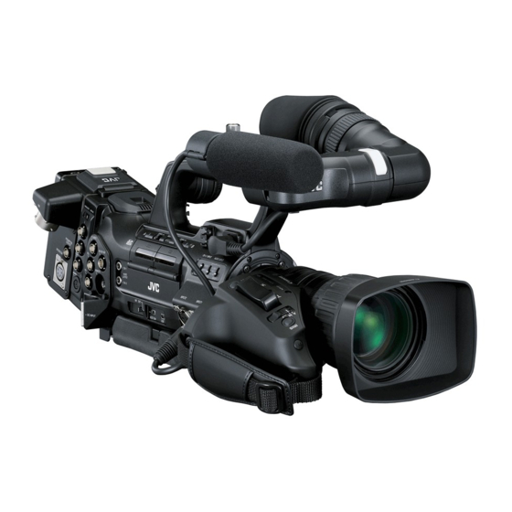
* The illustration shows the GY-HM790E with the supplied viewfinder, microphone and lens attached.
* GY-HM790CHU/GY-HM790CHE does not come with a lens.
COPYRIGHT © 2010 Victor Company of Japan, Limited
Note :
Lead free solder used in the board (material : Sn, Ag, In, Bi, melting point : 227 Centigrade)
1
PRECAUTION . . . . . . . . . . . . . . . . . . . . . . . . . . . . . . . . . . . . . . . . . . . . . . . . . . . . . . . . . . . . . . . . . . . . . . . . . . . . . . . . . . . . . . . . . .
1.1
SAFETY PRECAUTIONS . . . . . . . . . . . . . . . . . . . . . . . . . . . . . . . . . . . . . . . . . . . . . . . . . . . . . . . . . . . . . . . . . . . . . . . . . . .
2
SPECIFIC SERVICE INSTRUCTIONS . . . . . . . . . . . . . . . . . . . . . . . . . . . . . . . . . . . . . . . . . . . . . . . . . . . . . . . . . . . . . . . . . . . . . . .
3
DISASSEMBLY . . . . . . . . . . . . . . . . . . . . . . . . . . . . . . . . . . . . . . . . . . . . . . . . . . . . . . . . . . . . . . . . . . . . . . . . . . . . . . . . . . . . . . . . .
3.1
GENERAL DESCRIPTION . . . . . . . . . . . . . . . . . . . . . . . . . . . . . . . . . . . . . . . . . . . . . . . . . . . . . . . . . . . . . . . . . . . . . . . . . .
3.2
HOW TO REMOVE THE EXTERIOR PARTS . . . . . . . . . . . . . . . . . . . . . . . . . . . . . . . . . . . . . . . . . . . . . . . . . . . . . . . . . . .
3.3
HOW TO REMOVE THE OPTICAL BLOCK ASSEMBLY. . . . . . . . . . . . . . . . . . . . . . . . . . . . . . . . . . . . . . . . . . . . . . . . . . .
3.4
HOW TO REMOVE THE MAJOR BOARDS . . . . . . . . . . . . . . . . . . . . . . . . . . . . . . . . . . . . . . . . . . . . . . . . . . . . . . . . . . . .
3.5
HOW TO REMOVE THE HANDLE ASSEMBLY . . . . . . . . . . . . . . . . . . . . . . . . . . . . . . . . . . . . . . . . . . . . . . . . . . . . . . . .
3.6
HOW TO REMOVE THE VIEW FINDER ASSEMBLY . . . . . . . . . . . . . . . . . . . . . . . . . . . . . . . . . . . . . . . . . . . . . . . . . . . .
4
ADJUSTMENT . . . . . . . . . . . . . . . . . . . . . . . . . . . . . . . . . . . . . . . . . . . . . . . . . . . . . . . . . . . . . . . . . . . . . . . . . . . . . . . . . . . . . . . . .
4.1
FUNCTIONS REQUIRED FOR ADJUSTMENTS, SETUP . . . . . . . . . . . . . . . . . . . . . . . . . . . . . . . . . . . . . . . . . . . . . . . . .
4.2
STANDARD SETUP . . . . . . . . . . . . . . . . . . . . . . . . . . . . . . . . . . . . . . . . . . . . . . . . . . . . . . . . . . . . . . . . . . . . . . . . . . . . . .
4.3
ADJUSTMENT MENU . . . . . . . . . . . . . . . . . . . . . . . . . . . . . . . . . . . . . . . . . . . . . . . . . . . . . . . . . . . . . . . . . . . . . . . . . . . .
4.4
FLOWCHART OF ADJUSTMENTS . . . . . . . . . . . . . . . . . . . . . . . . . . . . . . . . . . . . . . . . . . . . . . . . . . . . . . . . . . . . . . . . . .
4.5
CAMERA ADJUSTMENTS . . . . . . . . . . . . . . . . . . . . . . . . . . . . . . . . . . . . . . . . . . . . . . . . . . . . . . . . . . . . . . . . . . . . . . . . .
5
TROUBLE SHOOTING . . . . . . . . . . . . . . . . . . . . . . . . . . . . . . . . . . . . . . . . . . . . . . . . . . . . . . . . . . . . . . . . . . . . . . . . . . . . . . . . . .
5.1
SERVICE MENUS . . . . . . . . . . . . . . . . . . . . . . . . . . . . . . . . . . . . . . . . . . . . . . . . . . . . . . . . . . . . . . . . . . . . . . . . . . . . . . .
5.2
EEP-ROM . . . . . . . . . . . . . . . . . . . . . . . . . . . . . . . . . . . . . . . . . . . . . . . . . . . . . . . . . . . . . . . . . . . . . . . . . . . . . . . . . . . . . .
5.3
HOW TO UPDATE THE FIRMWARE . . . . . . . . . . . . . . . . . . . . . . . . . . . . . . . . . . . . . . . . . . . . . . . . . . . . . . . . . . . . . . . . .
5.4
PRECAUTIONS WHEN CHANGING BOARDS . . . . . . . . . . . . . . . . . . . . . . . . . . . . . . . . . . . . . . . . . . . . . . . . . . . . . . . . .
TABLE OF CONTENTS
COPYRIGHT © 2010 Victor Company of Japan, Limited
1-3
1-3
1-5
1-5
1-5
1-5
1-7
1-8
1-11
1-12
1-14
1-14
1-14
1-15
1-17
1-18
1-22
1-22
1-27
1-28
1-30
No.HC034<Rev.001>
2010/11
Advertisement
Table of Contents

Related Manuals for JVC GY-HM790U


Summary of Contents for JVC GY-HM790U
-
Page 1: Table Of Contents
HD MEMORY CARD CAMERA RECORDER HC034<Rev.001> 2010 SERVICE MANUAL GY-HM790U, GY-HM790CHU, GY-HM790E, GY-HM790CHE * The illustration shows the GY-HM790E with the supplied viewfinder, microphone and lens attached. * GY-HM790CHU/GY-HM790CHE does not come with a lens. COPYRIGHT © 2010 Victor Company of Japan, Limited... - Page 2 10/30-60/30fps, 10/25-50/25fps, 10/24-60/24fps LCD monitor 4.3" LCD, 800 x 480 (WVGA, 410,000 pixels) Viewfinder 0.45" LCOS, 1.22 megapixels(852 x 480 x 3) Lens Section (GY-HM790U/GY-HM790E only) Lens Canon F/1.6, 14x, f = 4.4-61.6 mm ( 35 mm conversion: 32-448 mm) Filter diameter...
-
Page 3: Precaution
SECTION 1 PRECAUTION SAFETY PRECAUTIONS Prior to shipment from the factory, JVC products are strictly in- cathode ray tubes and other parts with only the specified spected to conform with the recognized product safety and elec- parts. Under no circumstances attempt to modify these cir- trical codes of the countries in which they are to be cuits.Unauthorized modification can increase the high volt-... - Page 4 1.1.2 Safety Check after Servicing Examine the area surrounding the repaired location for damage (4) Leakage current test or deterioration. Observe that screws, parts and wires have been Confirm specified or lower leakage current between earth returned to original positions, Afterwards, perform the following ground/power cord plug prongs and externally exposed ac- tests and confirm the specified values in order to verify compli- cessible parts (RF terminals, antenna terminals, video and...
-
Page 5: Specific Service Instructions
SECTION 2 SPECIFIC SERVICE INSTRUCTIONS This service manual does not describe SPECIFIC SERVICE INSTRUCTIONS. SECTION 3 DISASSEMBLY About CH model : CH models are without only lens assem- HOW TO REMOVE THE EXTERIOR PARTS bly. 3.2.1 Removing the left side cover assembly (See figure 1, GENERAL DESCRIPTION figure 2, figure 3, figure 4, figure 5, figure 6 and figure 3.1.1 Cautions... - Page 6 (3) Remove the two screws (S1), two screws (S11) and three (6) Disconnect the wire from the connector CN93 on the ECAP screws (S2) attaching the left side cover assembly. board. (S2) Left side cover assembly (S1) CN93 ECAP Board (S2) (S2) (S1)
-
Page 7: How To Remove The Optical Block Assembly
(2) Disconnect the wires from the connectors CN14, CN24, (4) Remove the mount screw. CN43 CN11 on the AUDIO board, then remove the Note: right side cover assembly. The glue has been applied to the mount screw. Replace with new one when the mount screw was removed. AUDIO Board (5) Remove the four screws (S8) attaching the optical block assembly, then remove the optical block assembly. -
Page 8: How To Remove The Major Boards
HOW TO REMOVE THE MAJOR BOARDS 3.4.3 Removing the CAM board, SDI board and CODEC board (See figure 18, figure 19, figure 20, figure 21 3.4.1 Removing the AUDIO board (See figure 15) and figure 22) (1) Remove the right side cover assembly (Refer to the 3.2.2) (1) Remove the left side cover assembly and right side cover (2) Disconnect the wires from the connectors CN10, CN44, assembly (Refer to the 3.2) - Page 9 (7) To remove the CAM board and the CODEC board, slide the 3.4.4 Removing the GENTC board and REG board (See fig- two boards together. ure 23, figure 24, figure 25, figure 26, figure 27, figure • As the CAM board and the CODEC board are connected 28, figure 29, figure 30 and figure 31) board to board, be very careful when removing and at- (1) Remove the right side cover assembly, and then discon-...
- Page 10 (4) Remove the four screws (S1) attaching the rear plate. (6) Remove the four screws (S6) attaching the GENTC board. CN78 (S1) (S1) (S6) (S6) GENTC Rear plate Board CN59 CN58 (S6) (S6) Fig.27 (S1) Fig.25 (7) Disconnect the wires from the connectors CN58, CN78, CN59, CN32, CN67, CN56, CN92, CN69, CN57 (5) Remove the four screws (S7) attaching the battery bracket.
-
Page 11: How To Remove The Handle Assembly
(8) Remove the four screws (S13) attaching the rear main base assembly. CN91 (S13) (S13) Rear main base CN31 assembly REG Board (S13) (S13) Fig.31 Fig.29 HOW TO REMOVE THE HANDLE ASSEMBLY (See fig- (9) Remove the four screws (S6) attaching the REG board. ure 32, figure 33, figure 34 and figure 35) (10) Disconnect the wires from the connectors CN109, CN30, (1) Remove the left side cover assembly and right side cover... -
Page 12: How To Remove The View Finder Assembly
(4) Disconnect the wire from the connector CN48 on the EAR HOW TO REMOVE THE VIEW FINDER ASSEMBLY board. 3.6.1 Removing the lens unit assembly (See figure 36, fig- (5) Remove the three screws (S4) attaching the handle as- ure 37 and figure 38) sembly. - Page 13 3.6.2 Removing the VF1 board and VF2 board (See figure (7) Remove the two screws D attaching the LCD module unit, 39, figure 40, figure 41, figure 42, figure 43 and figure then remove the LCD module unit. (1) Remove the lens unit assembly (Refer to the 3.6.1). LCD Module unit (2) Remove the two screws (S1) attaching the VF case B.
-
Page 14: Adjustment
SECTION 4 ADJUSTMENT FUNCTIONS REQUIRED FOR ADJUSTMENTS, SETUP 4.1.1 General instruments necessary for adjustment Instrument Condition Instrument Condition Oscilloscope Calibrated instrument with a measuring Frequency counter Instrument calibrated for 8 digits or more. bandwidth of 100 MHz or more. Stability of 0.1 ppm or 1x10 or better is re- quired at 0 to 40 °C. -
Page 15: Adjustment Menu
ADJUSTMENT MENU 4.3.1 Adjustment items : The items shown in gray screen below that they do not require the adjustment as the factory use only. Tops : To jump the menu items shown with bold items, press and hold the USER-3 button, and press USER-1 or USER-2 together at the same time. - Page 16 Adjustment Adjustment Display Display Adjustment item Mode Adjustment item Mode range range order order RESET START[B]R 0 to 63 60, 50, 48, 40 SHP PHASE[R]L 0 to 63 60, 50, 48, 40 RESET STOP[B]R 0 to 63 60, 50, 48, 40 SHD PHASE[R]L 0 to 63 60, 50, 48, 40...
-
Page 17: Flowchart Of Adjustments
FLOWCHART OF ADJUSTMENTS NOTE : As the camera adjustment data is stored in the EEP-ROM on the OP block, the split screen adjustments are complete at the factory before OP block assembly is supplied as service part. When replace the OP block assembly, only camera process adjustment is required. The SYS CPU has backup of the camera pro- cess adjustment data, so copy it from SYS to EEP-ROM on OP block by the service menu No. -
Page 18: Camera Adjustments
CAMERA ADJUSTMENTS 4.5.1 Encoder adjustment Vectorscope settings as follows. Saturation: 75%, SET UP: 7.5% Measuring Measuring Point (A) Item Instruments & Mode Adjustment Points (B) Adjustment Procedure Input Signals Adjustment Level (C) Preparation ADJUST MENU (C)60(NTSC) (1) Select ADJUST MENU No.1, "VIDEO MODE No.1 "VIDEO CHANGE"... - Page 19 4.5.2 Cam adjustment Measuring Measuring Point (A) Item Instruments & Mode Adjustment Points (B) Adjustment Procedure Input Signals Adjustment Level (C) Preparation (1) Attach the Lens and Lens connector to the unit. (2) Setting of Switches ND FILTER : OFF GAIN : L WHT.BAL : A FULL AUTO : OFF...
- Page 20 Measuring Measuring Point (A) Item Instruments & Mode Adjustment Points (B) Adjustment Procedure Input Signals Adjustment Level (C) Note: Before proceeding to perform the BLACK adjustment, be sure to warm up the OP Block for 15 minutes or more. BLACK Waveform ADJUST MENU (A)Y/VIDEO OUT...
- Page 21 4.5.3 HOB/VT White blemish adjustment NOTE: This adjustment is only required when the white blemish correction is mis-clamping. Measuring Measuring Point (A) Item Instruments & Mode Adjustment Points (B) Adjustment Procedure Input Signals Adjustment Level (C) HOB WHITE HD MONITOR ADJUST MENU (A)Y/VIDEO OUT (1) When color strip noise caused by the hori- SPOT...
-
Page 22: Trouble Shooting
SECTION 5 TROUBLE SHOOTING SERVICE MENUS 5.1.1 Modes required in servicing While holding down the specified button(s) (FOCUS ASSIST, USER 3), press the [MENU] button to display the first layer menu of the service menu hierarchy. The items in the first layer vary according to the specified button(s) being held when the [MENU] button is pressed. - Page 23 5.1.3 Firmware version display Item Parameter (1) Refer to 5.1.2.1 to display the VERSION MENU. IRIS ENF. While in the FULL AUTO mode, (2) The program number and version of the firmware package AUTO the IRIS mode depends on the are displayed.
- Page 24 (3) [PIXEL COMPEN EXECUTING] is displayed and the de- 5.1.5.1.2 SDI OUT Menu operation tection required for white blemish correction automatically (1) Open the ADVANCED FUNCTION Menu, move the cursor starts. to [SDI OUT], and then press the [Set] button or the [Cross- At this time, the camera lens is closed and the mode Shaped] button (right).
- Page 25 Refer to 5.1.5 ADVANCED FUNCTION Menu because the oper- 5.1.7 DIP SW Menu Operation ations are almost the same. (1) Refer to 5.1.2.3 to display the SERVICE MENU. (2) Move the cursor to [DIP SW], then press the [Set] button or Item Parameter the [Cross-Shaped] button (right).
- Page 26 Item Parameter --- DIP SW 5/8 --- DIP SW 3/8 DIP SW 16 to 18 OFF Change prohibited. DIP SW 19 and 21 0 DIP SW 20 DIP SW 22 and 23 OFF DIP SW 4/8 DIP SW 24 and 31 0 Change prohibited.
-
Page 27: Eep-Rom
5.1.10 OTHERS Menu Operation (1) Refer to 5.1.2.3 to display the SERVICE MENU. (2) Move the cursor to [OTHERS], then press the [Set] button or the [Cross-Shaped] button (right). (3) The OTHERS Menu is displayed. --- OTHERS --- ALL RESET CANCEL MEM. -
Page 28: How To Update The Firmware
NOTE: • The update file is named as "GY-HM790.UPD". • The update file should be put on the directory "//PRIVATE/JVC/GY-HM790", otherwise the update is not executed. (1) Download the update file from JS-NET SMIS and unzip it to a PC. - Page 29 5.3.2 Update procedure (1) While pressing the [MENU] and [FOCUS ASSIST(side)] buttons, turn ON the power. The VERSION menu is displayed immedi- ately, after the UPGRADE READY was displayed. --- VERSION --- FIRMWARE UPDATE READY EXIT After few seconds. Push the set button( ). (2) Insert the SD memory card into the card slot B.
- Page 30 Check the defect of board or the connection of each board, if the "update error !" was displayed. LCD display Update Error ! PRECAUTIONS WHEN CHANGING BOARDS After changing the board in service, firmware version update and adjustment may be required. 5.4.1 When version update is required For GY-HM790, there are multiple CPUs and FPGAs allocated on the two boards.
- Page 31 Victor Company of Japan, Limited Business Solution Division (No.HC034<Rev.001>) Printed in Japan...
Need help?
Do you have a question about the GY-HM790U and is the answer not in the manual?
Questions and answers