Table of Contents
Advertisement
Quick Links
HD MEMORY CARD CAMERA RECORDER
GY-HM700U
GY-HM700CHU
GY-HM700E
GY-HM700CHE
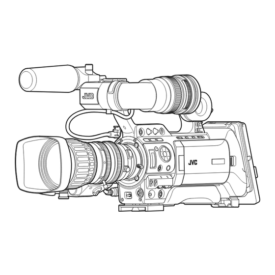
* The illustration shows the GY-HM700E with the supplied viewfinder, microphone and lens attached.
* GY-HM700CHU/GY-HM700CHE does not come with a lens.
For Customer Use:
Enter below the Serial No. which is located on the body.
Retain this information for future reference.
Model No.
GY-HM700U/GY-HM700CHU
Serial No.
INSTRUCTIONS
Please read the following before getting started:
Thank you for purchasing this JVC product.
Before operating this unit, please read the instructions
carefully to ensure the best possible performance.
In this manual, each model number is described without the last letter
(U/E) which means the shipping destination. (U: for USA and Canada,
E: for Europe)
Only "U"models (GY-HM700CHU/GY-HM700U) have been evaluated by
UL.
LST0904-001A
Advertisement
Table of Contents

Related Manuals for JVC HM700U - Camcorder - 1080p


Summary of Contents for JVC HM700U - Camcorder - 1080p
- Page 1 For Customer Use: Please read the following before getting started: Enter below the Serial No. which is located on the body. Thank you for purchasing this JVC product. Retain this information for future reference. Before operating this unit, please read the instructions Model No.
-
Page 2: Important Safeguards
Introduction FOR USA These are general IMPORTANT SAFEGUARDS and certain items may not apply to all appliances. IMPORTANT SAFEGUARDS Read all of these instructions. Save these instructions for later use. All warnings on the product and in the operating instructions should be adhered to. Unplug this appliance system from the wall outlet before cleaning. -
Page 3: Safety Precautions
CAUTION: REMARQUE: La plaque signalétique (plaque du numéro desérie) est située sur CHANGES OR MODIFICAT IONS NOT APPROVED BY JVC le cadre inférieur de l’unité. COULD VOID USER’S AUTHORITY TO OPERATE THE EQUIPMENT. CAUTION: To prevent electric shock, do not open the cabinet. - Page 4 (Business users) [REMOTE] Exclusive Cable If you wish to dispose of this product, please visit our web [LENS] Unshielded Cable 0.1m page http://www.jvc.eu to obtain information about the take- back of the product. [VF] Special Cable 0.3m [USB] Shielded Cable...
-
Page 6: Table Of Contents
Introduction Contents Shooting Basic Shooting Procedures ......34 Shooting ........34 Focus Assist Function . - Page 7 Media Menu ........89 ● All rights reserved by JVC. Unauthorized duplication or Setup File Manage Menu .
-
Page 8: Introduction
Shortens editing and output time by adopting MPEG-2 codec, which puts less stress on the editing computer. Application Software Provided The [JVC ProHD Clip Manager] application software is High Resolution via New [Triplex Offset] provided for you to copy recorded clips to Windows or 2.5kx1.4k pixels are generated with the new Triplex Offset... -
Page 9: Precautions For Proper Use
Precautions for Proper Use Power Saving When this device is not in use, be sure to set the [POWER] switch to OFF in order to reduce power consumption. Batteries Storage and Usage Locations The following batteries can be used on this device. GY-HM700CHU/GY-HM700U Allowable ambient temperature and humidity : Dionic90 (Anton Bauer) -
Page 10: Lcd Monitor And Viewfinder
Introduction Precautions for Proper Use LCD Monitor and Viewfinder (continued) The LCD monitor and viewfinder screens are manufactured using high-precision technology. Black spots may appear on the LCD monitor and viewfinder screens, or red, blue, and/or white spots may not turn off. However, this is not a malfunction and these spots are not recorded on the SDHC card. -
Page 11: Operation Mode
Operation Mode This camera recorder has three operation modes - Camera mode, Media mode, and USB mode. The operation mode indicator on the left side of the camera recorder lights up according to the mode. Camera Mode Media Mode [CAM/MEDIA] Selection Button IEEE1394 Camera Mode Mode... -
Page 12: Names Of Parts
Introduction Names of Parts Viewfinder (A Page 11) LCD Monitor (A Page 11) Zoom Lens (A Page 14) Side Control Panel (A Page 10) Front Tally Lamp (A Page 30) (A Page 87) Monitor Speaker (Cheek Pad) (A Page 26) Viewfinder Cable Clamp (A Page 20) Shoe For mounting separately sold lights and accessories. - Page 13 Battery Mount (A Page 21) SDHC Slot (A Page 13) Side Terminal (A Page 12) Back Tally Lamp (A Page 30) (A Page 87) [FOCUS ASSIST] Focus Assist Button (A Page 35) [PHONES] Earphone Connector (3.5) (A Page 45) Record Button Lock Switch [LENS] Lens Connector (12-pin Connector) Set the switch toward the lens to lock the [REC] trigger (A Page 19)
-
Page 14: Side Control Panel
Introduction Memo : Names of Parts (continued) ● Set the functions of the [USER1,USER2,USER3] buttons in the menu. (A Page 74) ● When the menu screen is displayed, these buttons function as the menu operation buttons. ( A Page 66 [Operation Buttons]) [MENU] Menu Button (A Page 66) Side Control Panel [ND FILTER] ND Filter Switch (A Page 43) -
Page 15: Viewfinder
Memo : LCD Monitor ● When [Camera Function][Switch Set...]B[AE LEVEL] is set to AE LEVEL/VFR , the cross-shaped button is used to set the number of frames during Variable Frame REC. ( A Page 56 [Variable Frame REC]) ( A Page 75 [AE LEVEL]) During Media mode (SD Card mode) (A Page 57) JKHI Thumbnail operation : Cross-shaped button (... -
Page 16: Side Terminal
Introduction Shoulder Pad Slide Button Names of Parts (continued) For adjusting the shoulder pad position. Press this button to adjust the shoulder pad K position to the front or back. Shoulder Pad [USB] USB Terminal (A Page 115) [IEEE1394] IEEE1394 Terminal (4-pin) Side Terminal For connecting digital video equipment with IEEE1394 terminal using an IEEE1394 cable (sold separately). -
Page 17: Sd Slot
SD Slot Rear (A Page 31) Card Slot A Status Indicator Shoulder Belt Mount (x2) For mounting a shoulder belt (sold separately). [SLOT SELECT] Card Slot Selection Button Note : For switching SDHC cards. ● Be sure to use a shoulder belt with the strength to withstand SDHC Card Cover the weight of this camera recorder. -
Page 18: Zoom Lens
Introduction Zoom Servo Control Lever Names of Parts (continued) To operate zoom servo with the zoom servo control lever, set the [ZOOM] switch M to SERVO . ● Zooms into wide angle and increases the angle of view when W is pressed. ●... -
Page 19: Basic System Diagram
Basic System Diagram Shoulder Belt SDI Cable Component Cable Monitor Microphone XLR 3P Composite Cable MV-P615 Earphone Audio Cable Focus Manual Unit RCA pin HZ-FM13 (FUJINON) HZ-FM15 (CANON) Monitor External Recording Microphone IEEE1394 Cable Device 4P-6P 1/3 Zoom Lens Th13x3.5BRMU(FUJINON) For GY-HM700CHU/GY-HM700U Anton Bauer 16 mm PL Mount... -
Page 20: Displays On The Lcd Monitor And Viewfinder
Introduction LCD monitor display Displays on the LCD The display switches between the 5 screen types with every press of the [STATUS] button. (STATUS 0B1B2B3B4B0) Monitor and Viewfinder Press the [DISPLAY] button to switch to the enlarged status display screen. (A Page 17) 30/24 fps You can display the camera status, media information, zebra pattern, and various markers in the video image on the LCD... -
Page 21: Enlarged Status Display On Lcd Monitor
Status Screen (VF/LCD) During Clip Status Screen in USB Mode Playback in Media Mode (SD Card Mode) This screen displays the USB mode. (A Page 96) The display switches between the 3 screen types with every press of the [STATUS] button. (STATUS 0B1B2B0) Enlarged Status Display on LCD Monitor STATUS 0 Screen You can enlarge and display only the characters of the status... -
Page 22: Auto White Display (Camera Mode Only)
Introduction Displays on the LCD Monitor Alarm Display ● Alarm is displayed during the status screen display in and Viewfinder (continued) Camera mode (STATUS 0, 1, 4) and Media mode. If the alarm sounds during STATUS 2 or 3 Screen display in Camera mode, the display will return to STATUS 0 Screen and alarm will be displayed. -
Page 23: Preparations
Preparations Attaching Accessories Attaching the Microphone (Supplied) You can attach the supplied microphone to the microphone holder. The supplied microphone has a phantom power supply. Turn the knob on the microphone holder anticlockwise to loosen and open the microphone Attaching the Zoom Lens holder. -
Page 24: Attaching The Viewfinder (Supplied)
Preparations Attaching Accessories Power Supply (continued) To use this camera recorder, you can attach a battery pack or connect an AC adapter to it. Attaching the Viewfinder (Supplied) ( A Page 21 [Using a Battery Pack]) ( A Page 21 [Using AC Power (DC IN Power)]) Slide the viewfinder in the direction of the arrow to attach it. -
Page 25: Using Ac Power (Dc In Power)
Using AC Power (DC IN Using a Battery Pack Power) Use an AC adapter (sold separately) to operate the camera recorder with AC power. Recommended Batteries U model : Dionic90 (Anton Bauer) Connect the DC cable of the AC adapter to the [DC E model : Endura-7 (IDX) INPUT] terminal of the camera recorder. - Page 26 Preparations Using a Battery Pack Attaching the Battery (GY-HM700CHE/GY- HM700E) (continued) Use the Endura-7 (IDX) battery. Attach the battery. Face the terminal downward and attach the V mount of the battery onto the V mount attachment bracket of the camera Attaching the Battery (GY-HM700CHU/GY- recorder.
-
Page 27: Precautions For Batteries
Note : Power Status Display ● The remaining battery power and time are displayed as there are from the battery information. Accurate data may Viewfinder and LCD Monitor Screens not be displayed according to the battery condition. Replace The power status is displayed on the status and menu the battery as soon as possible when the remaining battery screens. -
Page 28: Turning On/Off The Power
Preparations Camera mode Turning On/Off the Power Camera images are output on the viewfinder and LCD monitor. When a recordable SDHC card is inserted, the camera recorder enters the recording standby mode. STBY appears on the operation mode display area of the LCD monitor and viewfinder. -
Page 29: Setting The Clock (Initial Setting)
Specify [Time Zone] and [Date/Time]. Setting the Clock (Initial Move the cursor with the cross-shaped button ( ) and Setting) select the setting item. Change the values with the cross-shaped button ( Set the date/time of the built-in clock in the [Initial Setting] Press the Set button after setting is complete. -
Page 30: Adjusting The Monitor Speaker
Preparations Setting the Clock (Initial Adjusting the Monitor Setting) (continued) Speaker The monitor speaker can be rotated 180 degrees. Adjust according to the position of your ear. Changing the Display Style You can change the display style of the date/time on the 180 Degrees Rotation menu. -
Page 31: Adjusting Back Focus
Set the iris mode switch of the lens to M (manual). Adjusting Back Focus Set the zoom mode switch to MANU. (manual). Turn to open the iris ring. When the lens is first attached, adjust the back focus of the Adjust the lighting such that the optimum image level can be lens if the focus is not clear when zoomed to the telephoto or obtained. -
Page 32: Adjusting The Lcd Monitor And Viewfinder
Preparations ● Use the [LCD PEAKING +/-] button to adjust the contour of Adjusting the LCD Monitor the LCD monitor screen. Press the [+] and [-] buttons simultaneously to return to standard settings. and Viewfinder [+] : Press the button to increase contour correction. [-] : Press the button to decrease contour correction. - Page 33 Adjusting the Angle When [LCD + VF] in the [LCD/VF] menu is set to Off (A Page 82) Adjust the position and angle of the viewfinder. Displays on the LCD monitor and viewfinder screens (VF) are indicated as below. Adjusting the Visibility LCD Monitor Status LCD Display VF Display...
-
Page 34: Tally Lamps
Preparations Tally Lamps These are indicator lamps for recording and warning. The operation changes according to the menu settings. When the battery or remaining space on the SDHC card is low, the lamps blink. (Camera mode only) * Set using [Tally System]/[Front Tally]/[Back Tally] in the [Main Menu]B[Others...] menu. (A Page 87) Front Tally Lamp Back Tally Lamp [Tally System]... -
Page 35: Sdhc Cards
Card Slot Status Indicator SDHC Cards The following table shows the respective states of slot A and B. Lamp Slot Status Lights up in red Inserted SDHC card is being accessed. (writing/reading data) Do not turn off the power of the camera This camera recorder saves the recorded images and audio recorder or remove the SDHC card. -
Page 36: Formatting (Initializing) Sdhc Cards
Preparations Select the slot of the SDHC card to be formatted and SDHC Cards (continued) press the Set button. Switching SDHC cards When both card slots are inserted with SDHC cards, you can use the [SLOT SELECT] button to switch the card to use. When the memory on an SDHC card is full during recording, data recording automatically switches to the other card. -
Page 37: Restoring The Sdhc Card
Note : Restoring the SDHC Card ● [Restore Media] can only be selected in Camera mode. However, it cannot be selected while the camera recorder is It is necessary to restore the SDHC card if an abnormality occurs to the data in the card due to some reasons. recording. -
Page 38: Shooting
Shooting Basic Shooting Procedures [REC] Button Back Tally Lamp Front Tally Lamp [POWER] Switch [REC] Button Press the [REC] button to start recording to the SDHC Preparations card. ● There are two [REC] buttons on the camera recorder and Attach the accessories. (A Page 19) one on the lens. -
Page 39: Focus Assist Function
When copying clips to a HDD using a PC, it is recommended VF]B[Shooting Assist...]B[Color]. (A Page 83) to use [JVC Clip Manager Software], which is found in the bundled CD-ROM, to maintain continuity. Assigning Focus Assist function to the [RET] Note : ●... -
Page 40: Selecting File And Video Formats
Shooting Record Format Remarks Selecting File and Video File Format Camera Resolution Frame & Bit Formats Rate Horizontal×Line 1280x720 60p(HQ) 60p(SP) compatible You can select the file format for recording/playback and the 30p(HQ) record format for video images on this camera recorder. 30p(SP) compatible 24p(HQ) -
Page 41: Adjusting The Iris
Adjusting the Iris Setting Gain You can adjust the aperture of the lens iris manually or This function electrically boosts the light sensitivity when automatically according to the brightness of the object. there is insufficient illumination on the object. You can set the gain of the video amplifier according to the brightness of the Iris Ring object. -
Page 42: Setting The Electronic Shutter
Shooting Switching Shutter Speed Setting the Electronic When shutter is ON, use the [SHUTTER] switch ( ) to set Shutter the shutter speed. Shutter speed differs according to the video format and variable frame rate settings. During modes other than Variable Frame REC You can change the shutter speed (time for each shooting Camera 720/60p... - Page 43 Camera Resolution/ 720/25p Frame & Bit Shutter Rate Frame Rate 50, 25, 12.5 40, 20, 10 Button 1/10000 1/10000 1/4000 1/4000 1/2000 1/2000 1/1000 1/1000 1/500 1/500 1/250 Step 1/250 1/120 1/120 1/50 (Standard) 1/50 1/40 1/25 1/20 1/12.5 1/10 Button 1/6.25 Button...
-
Page 44: Adjusting The White Balance
Shooting Memory A Mode (A), Memory B Mode Adjusting the White Balance Set to the white balance saved in Memory A or Memory B. When the [WHT.BAL.] selection switch is set to [A] or [B], press the [AWB] button to execute white balance. The white balance will be automatically adjusted and the adjusted Adjust the white balance according to the color temperature value will be saved in Memory A or Memory B. - Page 45 Error message If the white balance adjustment is not correctly completed, one of the following messages will appear for about 5 seconds. Error Message Status NG : OBJECT The object used is defective. Displayed when there is not enough white color on the object, or when the color temperature is not suitable.
-
Page 46: Adjusting The White Shading
Shooting Select the item to change with the cross-shaped button Adjusting the White ) and press the Set button ( Shading Change the setting value with the cross-shaped button while looking at the evaluated value at the bottom right of the LCD monitor or viewfinder screen. -
Page 47: Setting The Nd Filter
Setting the ND Filter Use the ND filter to keep the lens aperture in the appropriate range. Switch according to the brightness of the object. When the switch is changed, the position of the switched ND filter is displayed on the LCD monitor and viewfinder screens. (STATUS 1 Screen) [ND FILTER] Switch... -
Page 48: Adjusting Audio Input Settings And Recording Level
Shooting Adjusting Audio Input Adjusting Audio Recording Level Settings and Recording You can select to adjust the audio recording levels for the two channels (CH-1/CH-2) manually or automatically. Level You can record audio from the two channels (CH-1/CH-2) in [AUDIO LEVEL synchronization with video images on this camera recorder. -
Page 49: Audio Monitor During Recording
Using Stereo Type Earphone Jack Note : ● When the [FULL AUTO] switch on the camera recorder is set When a stereo type earphone jack is connected, perform the to ON , the recording level cannot be adjusted with the following setting to output stereo sound. -
Page 50: Setting Time Code And User's Bit
Shooting Memo : Setting Time Code and ● The built-in time code generator number is displayed. ● Time code display for [IEEE1394] input is not supported. User’s Bit ● Values recorded on the SDHC card is displayed in Media mode. Time code and user’s bit data are recorded with the video in VIDEO Output Setting Display... - Page 51 Setting Time Code Presetting the Time Code [USER2] Button Time code and user’s bit data generated from the internal time code generator are recorded. This section describes how to set [TC Preset] in the [TC/UB] menu. (A Page 82) [MENU] Button Set Button ( [USER2] Button Cross-...
-
Page 52: Presetting The User's Bit
Shooting Check the values and press the cross-shaped button ( Setting Time Code and ● The time code is set and the screen returns to [TC/UB]. User’s Bit (continued) ● To cancel the setting, press the [CANCEL] button. Press the [MENU] button. Returns to the normal screen. -
Page 53: Setting User's Bit Without Opening The Menu
Set the time code (hour, minute, second, frame). Set the user’s bit. Use the cross-shaped button ( ) to place the cursor at the Use the cross-shaped button ( ) to place the cursor at the item to set, then the cross-shaped button ( ) to change item to set, then the cross-shaped button ( ) to change... -
Page 54: Setting Zebra Pattern
Shooting Memo : Setting Zebra Pattern ● Top2 and Bottom2 cannot be set if [Zebra] is set to 1Pattern . ● When the specified range of two zebra patterns overlaps, the two zebra patterns overlap and are displayed in a grid. When the luminance level range for displaying zebra patterns is specified, diagonal lines (zebra pattern) are displayed at areas with the specified luminance levels during shooting. -
Page 55: Setting Spot Meter
Flip the [SKIN AREA/SPOT METER] switch of the camera Setting Spot Meter recorder. The operation switches as below when the [SKIN AREA/ SPOT METER] switch is flipped. When [Max&Min]/[Max]/[Min] is selected The brightness of the object during shooting is displayed. [SPOT METER ON] is displayed when the switch is This function is useful when setting video or stage lighting or flipped. -
Page 56: Viewing Recorded Videos Immediately (Clip Review)
Shooting Setting Spot Meter Viewing Recorded Videos (continued) Immediately (Clip Review) You can check (review) the last recorded video clip on the When [Manual] is selected screen. [SPOT METER FIXED] is displayed when the switch is However, the video clip cannot be played back if the settings of the camera recorder are different from the video format flipped. -
Page 57: Assigning Functions To User Buttons
Note : Assigning Functions to ● During Clip Review, only the [CANCEL] and [REC] buttons User Buttons are enabled. Press the [CANCEL] button to cancel clip review and return to STBY (recording standby) mode. Press the [REC] button to cancel clip review and enter recording mode. -
Page 58: Protecting Important Scenes (Ok Mark Function)
Shooting Protecting Important Special Recording Scenes (OK Mark Function) You can append OK marks to the clips for important scenes. Besides the normal recording mode, three special recording methods are available in this camera recorder. They are Pre Clips appended with OK marks cannot be deleted, thus REC, Clip Continuous REC, and Variable Frame REC. -
Page 59: Clip Continuous Rec
Resume recording. (Recording 3) Clip Continuous REC ● Press the [REC] button again to resume recording. The In normal recording, when the recording stops, the image, display changes to STBYC (red text) B RECC . audio, and accompanying data from the start till the end of ●... -
Page 60: Variable Frame Rec
Shooting Note : Special Recording ● The recording frame rate cannot be changed during (continued) recording. To change the frame rate, stop the recording first and perform the change. ● When the [TC GENE.] switch located on the inner panel of the LCD is set to FREE , videos are recorded in REC (RecRun) time code. -
Page 61: Playback
Playback Playing Back Recorded Thumbnail Screen Clips The thumbnail screen is available in “No Detailed Properties (4x3 thumbnails)” and “Detailed Properties (4x1 thumbnails)” displays. Use the thumbnail menu [Detailed Properties] to switch display. (A Page 61) To play back clips recorded on SDHC cards, switch to the Media mode (SD Card mode). - Page 62 Playback Playing Back Recorded Name Description Video Displays the video format (Camera Clips (continued) Resolution/Frame Rate) that allows playback Format and thumbnail display. Available in 4 types: [1080/60i, 30p, 24p], [1080/50i, 25p], [720/60p, 30p, 24p], and [720/50p, 25p]. Clips of other video formats are represented in alternative display.
- Page 63 Name Description Clip Mark Displays clip information (properties). OK Mark Clip is appended with OK mark. Memo : ● Clips appended with OK marks cannot be deleted on the camera recorder. Continued From Mark This mark indicates that the current clip is continued from another SDHC card when recording is divided and made on several SDHC cards.
- Page 64 Playback Playing Back Recorded Name Description Detailed Shows the detailed properties of the selected Clips (continued) clip. The following information is displayed. Properties File Format : File format Clip Name : Clip name Resolution : Image size Frame Rate : Frame rate Bit Rate : Bit rate Audio...
-
Page 65: Playing Back
Thumbnail Menu Playing Back Use the operation buttons on the side control panel of the camera recorder to play back. Press the [MENU] button during thumbnail display to display the thumbnail menu. Press the [MENU] button during menu display to cancel the settings and exit the menu. -
Page 66: Deleting Clips
Playback Press the [USER2] button. Deleting Clips A screen to confirm deletion appears. Use the cross-shaped button ( ) to select [Delete] and press the Set button ( Deleting starts. For deleting clips. [USER2] Button [MENU] Button Set Button ( Cross- Shaped Button... - Page 67 Use the cross-shaped button ( ) to select [Delete] and press the Set button ( Deleting starts. Deleting All Clips Memo : ● Button operations are unavailable during deletion. The Deletes all clips that are displayed. deleting operation cannot be canceled. Press the [MENU] button.
-
Page 68: Appending And Deleting Ok Marks
Playback Appending and Deleting OK Marks OK Mark You can append OK marks to the clips for important scenes. Clips appended with OK marks cannot be deleted, thus protecting the important clips. When the camera recorder is in Media mode (SD Card mode), you can delete the [OK] marks appended during Memo : recording, or append/delete [OK] marks after shooting. - Page 69 During Playback or Pause Screen Deleting OK Marks Press the [USER1] button when playing back a clip During Thumbnail Screen appended with OK mark. The OK mark is deleted. Select a clip to delete OK mark and press the [USER1] button.
-
Page 70: Menu Display And Detailed Settings
Menu Display and Detailed Settings Basic Operations in Menu Display and Description of the Menu Screen Screen Screens of the Selected Menu Items Press the [MENU] button on the side control panel of the camera recorder to display the menu screen on the LCD monitor and viewfinder. -
Page 71: Text Input With Software Keyboard
Changing Setting Values [Clip Name Prefix] Name Description Name Description Character Entry Field for entering the title. Menu Item to Menu item to be changed. A list of setting values C appears in Field You can enter up to 8 characters for Change the [Scene File]/[Picture File] a pop-up. -
Page 72: Menu Screen Hierarchical Chart
Menu Display and Detailed Settings Menu Screen Hierarchical Chart Main Menu... (A Page 70) Record Set...(A Page 71) Record Format(A Page 71) File Format Camera Resolution Frame & Bit Rate Rec Mode (A Page 71) Clip Set (A Page 72) Clip Name Prefix Reset Clip Number Audio Set (A Page 72) - Page 73 TC/UB... (A Page 82) TC Preset UB Preset Drop LCD/VF... (A Page 82) Shooting Assist... (A Page 83) Marker Setting... (A Page 84) Status Display... (A Page 84) LCD + VF VF Display LCD Mirror Mode A/V Out... (A Page 86) Output Terminal Down Convert Set Up...
-
Page 74: Main Menu Screen
Menu Display and Detailed Settings Main Menu Screen Some menus cannot be set depending on the operating mode or status of the camera. These items are displayed in gray, and they cannot be selected. Item Function Record Set Menu screen for specifying video or audio settings during shooting and playback. The cursor does not move to this item during recording or in Media mode. -
Page 75: Record Set Menu
Record Set Menu Record Format Menu * Default values are indicated in bold characters. Item Setting Values Function File Format QuickTime For selecting the format of the file to be recorded to the SDHC card. Note : ● MP4 can only be selected when KA-MR100G (Memory Recorder) is connected. -
Page 76: Clip Set Menu
Menu Display and Detailed Settings Record Set Menu (continued) Clip Set Menu * Default values are indicated in bold characters. Item Setting Values Function Clip Name Prefix xxxG For setting the first 4 characters of the name of the clip file to be recorded to the SDHC card. -
Page 77: Camera Function Menu
Camera Function Menu * Default values are indicated in bold characters. Item Setting Values Function Bars For setting whether to output color bars. : Color bars are output. : Color bars are not output. Memo : ● When the [FULL AUTO] switch on the camera recorder is set to ON , and [Bars] in the [FULL AUTO...] menu is set to Off , this item is set to Off automatically. -
Page 78: Switch Set
Menu Display and Detailed Settings Camera Function Menu (continued) Switch Set... Item * Default values are indicated in bold characters. Item Setting Values Function None For assigning the FAW (Fulltime Auto White Balance) function to a position on the [WHT.BAL.] selection switch. -
Page 79: Full Auto
* Default values are indicated in bold characters. Item Setting Values Function SKIN A./SPOT M. Skin Area For assigning the function of the [SKIN AREA/SPOT METER] switch on the camera recorder. Skin Area : Assigns the Skin Detail function and its area display. Spot Meter Spot Meter : Assigns the Spot Meter display function. -
Page 80: Camera Process Menu
Menu Display and Detailed Settings Camera Process Menu * Default values are indicated in bold characters. Item Setting Values Function Detail Max, 9 to 1, For adjusting the contour (detail) enhancement level. Increase the number : Sharpens the contour. Normal, Decrease the number : Softens the contour. - Page 81 * Default values are indicated in bold characters. Item Setting Values Function White Clip 100% For setting the point to apply white clip for input video signals with a high luminance level. 108% 100% : Applies white clip at the point where the luminance level is 100 %. Even when this item is set to 108% , it switches automatically to 100% if the screen appears too white.
-
Page 82: Detail/Adjust
Menu Display and Detailed Settings Camera Process Menu (continued) Detail/Adjust... Item * Default values are indicated in bold characters. Item Setting Values Function V/H Balance H-Max, 4 to1, For setting the H/V balance to enhance contour (detail) in the horizontal (H) or vertical (V) direction. -
Page 83: White Balance
White Balance... Item * Default values are indicated in bold characters. Item Setting Values Function Preset Temp. 5600K For setting the color temperature when the [WHT.BAL.] selection switch of the camera recorder is set to PRESET . 3200K White Paint R Max, 30 to 1, For adjusting the R (red) component in the AWB (Auto White Balance) mode. -
Page 84: Shading Mode/Adjust
Menu Display and Detailed Settings Camera Process Menu (continued) Shading Mode/Adjust... Item * Default values are indicated in bold characters. ● This item is selectable only when [Shading Mode] is set to Manual . [R Level], [G Level], and [B Level] cannot be selected when this is set to Preset . - Page 85 * Default values are indicated in bold characters. Item Setting Values Function G&Cy G Level Max, 19 to 1, For adjusting the green/cyan level of the video toward green. Increase the number : Enhances the green component of green/cyan. Normal, Decrease the number : Reduces the green component of green/cyan.
-
Page 86: Tc/Ub Menu
Menu Display and Detailed Settings TC/UB Menu * Default values are indicated in bold characters. Item Setting Values Function TC Preset For setting the time code (hour, minute, second, frame). Display : Drop setting 02:02:25.20 : Non Drop setting 02:02:25:20 UB Preset For setting the user’s bit. -
Page 87: Shooting Assist
Shooting Assist... Item * Default values are indicated in bold characters. Item Setting Values Function Focus Assist ACCU-Focus For specifying the operation when the [FOCUS ASSIST] button on the camera recorder is pressed. (A Page 35) Normal ACCU-Focus : Enables the Focus Assist and ACCU-Focus (forced focus) functions. The depth of field of the object becomes shallower to enable easier focusing. -
Page 88: Marker Setting
Menu Display and Detailed Settings LCD/VF Menu (continued) Marker Setting... Item ( A Page 100 [Marker and Safety Zone Displays (Camera Mode Only)]) * Default values are indicated in bold characters. Item Setting Values Function Aspect Ratio *1 4:3, 14:9, For selecting the final image aspect ratio to be used from the overall angle of view. - Page 89 * Default values are indicated in bold characters. Item Setting Values Function TC/UB For specifying whether to display the time code/user’s bit rate in the status display on the LCD monitor and viewfinder screens. : Displays the time code or user’s bit rate. Whether time code or user’s bit rate is displayed is determined by the setting of the [TC DISPLAY] switch on the inner panel of the camera recorder’s LCD monitor.
-
Page 90: A/V Out Menu
Menu Display and Detailed Settings A/V Out Menu * Default values are indicated in bold characters. Item Setting Values Function Output Terminal Composite For setting output signals from the [Y/VIDEO]/[PB]/[PR] video signal output terminal (BNC) on the side of the camera recorder. Component Composite : Outputs composite signals to the [Y/VIDEO] video signal output terminal. -
Page 91: Others Menu
* Default values are indicated in bold characters. Item Setting Values Function Audio Monitor Stereo For setting the audio sound of the [PHONES] terminal to stereo or mixed sound when the [MONITOR SELECT] switch on the side of the camera recorder is set to Both . : Outputs mixed sound (outputs mixed sound of CH-1 and CH-2 to both L and R). - Page 92 Menu Display and Detailed Settings Others Menu (continued) * Default values are indicated in bold characters. Item Setting Values Function 1394 Rec Trigger For setting the recording trigger for the external recording device connected to the [IEEE1394] terminal. Series : Outputs recording trigger to the external system only. (Recording is not Split performed by the internal system.) Series...
-
Page 93: Media Menu
Media Menu * Default values are indicated in bold characters. Item Function Format Media For formatting (initializing) an SDHC card. Select a card slot (A or B), select [Format] from [Cancel]/[Format], and press the Set button to format (initialize) the card. ( A Page 32 [Formatting (Initializing) SDHC Cards]) Restore Media For restoring an SDHC card. -
Page 94: Status Screen
Status Screen Status Screen in Camera Mode STATUS 0 Screen 30/24 fps * Appears only when a warning is displayed (A Page 92) 20 min MAX 123% SKIN AREA S.DTL A A A 1min B -3 1min A<3200K> STBY F5.6 AE+1 9dB 1/10000 Item Description... - Page 95 Item Description Skin Detail Operation Appears as S.DTL when the Skin Detail function is turned ON. Operation of Functions SKIN AREA : Blinks when the Skin Area display is ON. FOCUS : Appears when the Focus Assist function is activated. When ACCU-Focus is enabled, ACCU-FOCUS blinks for about 10 seconds while Focus Assist starts up, after which the FOCUS indicator lights up.
- Page 96 Status Screen Status Screen in Camera Mode (continued) STATUS 1 Screen * 0 : Same as STATUS 0 Screen (A Page 90) 1280x720 30/24 fps 0 0 : 0 0 : 0 0 : 0 0 60p HQ 20 min MAX 123% SKIN AREA S.DTL...
- Page 97 Item Description ND Filter Position Displays the current ND filter position. No display : [ND FILTER] is set to OFF ND1/4 : [ND FILTER] is set to 1/4 ND1/16 : [ND FILTER] is set to 1/16 Memo : ● You can turn ON/OFF the display using [Filter] of [Status Display...] in the [LCD/VF] menu. (A Page 84) Remaining Space on Displays the remaining recording time of the external device (0 to 999).
- Page 98 Status Screen Status Screen in Camera Mode (continued) STATUS 2 Screen CAMERA INFORMATION SETUP FILE SCENE [ SCENE ZEBRA1 50%-100% ZEBRA2 70%-80% AUDIO FORMAT QuickTime MEDIA 125min 123min * 0 : Same as STATUS 0 Screen (A Page 90) 282min STBY Jan 2.
- Page 99 STATUS 3 Screen This screen displays a list of the functions assigned to the switches. * 1 : Appears only when a warning is displayed SWITCH ASSIGN NONE GAIN [ L / M / H ] 0dB / 9dB / 12dB USER 1 BARS USER 2...
-
Page 100: Status Screen In Sd Card Mode
Status Screen Status Screen in SD Card Mode These are the status screens displayed in Media mode (SD Card mode, Media mode). STATUS 0 Screen This screen displays the media status or event. It is also used to display warnings only. STATUS 1 and STATUS 2 Screens STATUS 1 Screen STATUS 2 Screen... - Page 101 Item Description Date/Time Displays the date/time that is recorded on the currently played SDHC card. Note : ● The date/time display style can be specified at [LCD/VF]B[Status Display...]B[Date Style]/[Time Style]. (A Page 85) Audio Level Meter Displays the audio level for CH-1 and CH-2. -20 dB -10 dB The positions of -20 dB and -10 dB are displayed as...
-
Page 102: Status Screen In 1394 Mode
Status Screen Status Screen in 1394 Mode These are the status screens displayed in Media mode (IEEE1394 Input mode). STATUS 1 Screen [Event/Warning Display Area] (A Page 91 ) * Appears only when a warning is displayed [Voltage/Remaining Battery Power] (A Page 98 ) STATUS 2 Screen [Event/Warning Display Area] (A Page 91 ) 1280x720... -
Page 103: Enlarged Status Display On Lcd Monitor
Enlarged Status Display on LCD Monitor You can enlarge and display only the characters of the status screen on the LCD monitor. FREE STBY STOP REVIEW 1280 x 720 STBY 60p HQ 100min 67.8min 123 min Item Description Audio Level Meter Displays the audio levels of [CH-1] and [CH-2]. -
Page 104: Camera Features
Camera Features Marker and Safety Zone Displays (Camera Mode Only) The marker and safety zone displays are useful in helping you determine the angle of view for the image according to the shooting purpose. Example of display when [Aspect Ratio] = 4:3 , [Aspect Marker] = Line+Halftone , and [Center Mark] = On Center Mark Safety Zone Aspect Marker... - Page 105 [Safety Zone] Display When [Aspect Ratio] = 4:3 , [Aspect Marker] = Halftone , and [Center Mark] = On [Off] [95%] [93%] [90%] [88%] [80%] [Center Mark] Display When [Aspect Ratio] = 4:3 , [Aspect Marker] = Halftone , and [Safety Zone] = 80% [Off] [On] When [Aspect Ratio] = 4:3 , [Aspect Marker] = Halftone , and [Safety Zone] = Off...
-
Page 106: Smoothening The Skin Color (Skin Detail Function)
Camera Features Color Range Setting Smoothening the Skin Place the cursor at [Skin Color Range] with the cross- Color (Skin Detail shaped button ( Function) Press the Set button or cross-shaped button ( ) to move the cursor to a setting value. The Skin Detail function can be used to reduce the contour enhancement of video signals for only the skin areas so as to produce a smoother skin tone. -
Page 107: Color Bar Output
Color Bar Output Checking the Preset Hue Area Set the [ZEBRA ON/OFF] switch at the front of the camera recorder to the [SKIN AREA/SPOT METER] end. Doing so forcibly turns ON the Skin Adjust function temporarily, and the preset hue area is displayed in color on Multi-format color bars can be output on this camera the LCD monitor and viewfinder. -
Page 108: Color Matrix Adjustment
Camera Features R&Yl R Level Increase the value: Color Matrix Adjustment Corrected Y increases Decrease the value: Corrected Y decreases The color matrix of the camera recorder can be adjusted to a color of the user’s preference. R&Yl Yl Level Increase the value: When shooting is performed using multiple cameras, the Corrected Y decreases... - Page 109 Adjust the hue. B&Mg B Level Increase the value: Corrected Y increases Adjust the hue based on the R-, G-, and B-axes. As illustrated in the chart below, increasing the value rotates Decrease the value: the hue in the anti-clockwise direction on the vector scope, Corrected Y decreases with the respective axes as the center.
-
Page 110: Reproduction Of Dark Areas (Black Stretch/Compress Function)
Camera Features Reproduction of Dark Areas (Black Stretch/ Compress Function) Process the dark areas according to the balance of bright and dark areas in the image to adjust the overall balance of contrast. Adjust [Black Toe] in the [Camera Process...] menu according to the captured video signals. -
Page 111: Configuring Setup Files
Number of storable setup files Configuring Setup Files Camera recorder : [CAM1] to [CAM4] SDHC Card Slot A : A[EXT1] to A[EXT8] Slot B : B[EXT1] to B[EXT8] The menu settings of can be stored on the camera recorder or an SDHC card by saving them as a setup file. Preset setup files Loading a saved setup file enables you to reproduce the As described below, there are three types of scene files and... -
Page 112: Saving Setup Files
Camera Features Configuring Setup Files (continued) Saving Setup Files Display the [Setup File Manage] menu. Select the [Setup File Manage] menu on the [Main Menu...] screen, and press the Set button. (A Page 89) Select [Store File...] and press the Set button. Select [Scene File] or [Picture File], and press the Set Memo : button. -
Page 113: Loading A Setup File
Select [Store] from the confirmation buttons E, and Select [Load] on the confirmation screen, and press press the Set button. the Set button. A confirmation screen appears. Loading starts, and Loading... appears on the screen. Select [Store] on the confirmation screen, and press the Set button. -
Page 114: Connecting External Devices
Connecting External Devices Connecting an External Connecting via SDI Monitor Either HD-SDI or SD-SDI signals can be output from the [HD/SD-SDI] terminal (BNC) on the terminal area of the camera recorder. ● Digital audio signals, together with embedded (superimposed) audio signals and time code signals, are To output live or playback video images and audio sound to an external monitor, select the output signals from the output for both the HD-SDI and SD-SDI signals. -
Page 115: Ieee1394 Connection
Note : [PHONES] Terminal ● When connecting the camera recorder to an external device using an IEEE1394 cable, make sure to observe the Audio output from the [PHONES] terminal can be selected using [Audio Monitor] in the [A/V Out] menu (A Page 87) as following. -
Page 116: Backup Recording
Connecting External Devices Set the external device to a mode that enables IEEE1394 Connection recording. (continued) For setting and operation of external devices, refer to the instruction manual of the respective devices. Note : ● Adjust the camera recorder and external device to the same IEEE1394 settings. -
Page 117: Stream Transmission To A Non-Linear Editing System
Start loading to the non-linear editing system. Stream Transmission to a Non-linear For details, refer to the instruction manual of the non-linear Editing System editing system. Playback images on the camera recorder can be stream output during editing using a non-linear editing system. Loading is complete. -
Page 118: Managing/Editing Clips On A Pc
● Files cannot be written to the SDHC card. ● If playback is in progress, the camera recorder switches to ● Make sure to manage/edit the files using the (JVC ProHD USB mode after the file closes automatically, such as when Clip Manager) PC application software in the bundled CD- playback stops. -
Page 119: Remote Control Unit Connection
Precautions for Using the Remote Remote Control Unit Control Unit Connection ● When the switches of the camera recorder and remote control unit are operated at the same time, the switch operation of the remote control takes priority over that of the camera recorder. -
Page 120: List Of Remote Control Unit Functions
Connecting External Devices : Available Remote Control Unit Function -: Not available Connection (continued) MASTER BLACK TALLY (LED) CALL *4 PREVIEW AUTO KNEE List of Remote Control Unit Functions KNEE POINT RM-LP25U BARS TALLY(PGM) *4 Rear Input : Available Function -: Not available TALLY(PVW) *4 Rear Input... - Page 121 RM-P57U : Available Function -: Not available MODE BARS, CAM H.PHASE SC COARSE 0 , 90 , 180 , 270 SC FINE CONTOUR OFF, ON LEVEL GAIN +6dB +9dB +12dB +18dB ALC+EEI WHITE BAL AUTO1 AUTO2 AUTO WHITE PAINT SHUTTER 1/100 *1, 1/120 *2 1/250 1/500...
-
Page 122: Others
TURN POWER OFF System error. Turn off the power, and turn it on again. TURN BACK ON If the error persists, consult your nearest JVC * The alarm sounds and the tally lamp blinks LATER dealer. about once every second. -
Page 123: Tally Lamps
● Usage time of the fan has FAN MAINTENANCE Check the fan and replace accordingly. For REQUIRED exceeded 9000 hours. more details, consult your nearest JVC dealer. Memo : ● You can check the usage time of the fan at [Others...]B[System Information]B[Fan Hour]. -
Page 124: Troubleshooting
Others Troubleshooting Symptom Action ● Is the AC adapter properly connected? Power does not turn on. ● Is the battery charged? ● Is the power turned on immediately after it is turned off? Make sure to wait for an interval of at least 5 seconds before turning on the power again. ●... - Page 125 Symptom Action ● The date and time are only displayed on the STATUS 2 and STATUS 3 Screens in The date and time are not displayed. the Camera mode (during shooting). (A Page 94)(A Page 95) ● Is [Output Terminal] in the [A/V Out...] menu correctly set? (A Page 86) No output from the [Y/VIDEO], [PB], and [PR] video signal output terminals.
-
Page 126: Specifications
: 3.5 mm mini jack (stereo) x 2 Lens : Canon F/1.6, 14x, f = 4.4-61.6 mm (35 mm conversion: 32-448 mm) [REMOTE] terminal : 6-pin JVC remote control connection Filter diameter : 82 mm [IEEE1394] terminal : 4-pin [USB] terminal : Mini USB-B type, USB 2.0, miniB,... - Page 127 Accessories Microphone Lens (GY-HM700U/GY-HM700E only) Instructions CD-ROM Warranty Card (GY-HM700CHU/GY-HM700U only) Dimensional Outline Drawing (Unit: mm) (VF MOVE) (for ANTON BATTERY) (166) (S.PAD MOVE) (for IDX BATTERY) * The specifications and appearance of this product are subject to changes for further improvement without prior notice.
- Page 128 LST0904-001A 2009 Victor Company of Japan, Limited...
Need help?
Do you have a question about the HM700U - Camcorder - 1080p and is the answer not in the manual?
Questions and answers