Table of Contents
Advertisement
Advertisement
Table of Contents

Subscribe to Our Youtube Channel
Related Manuals for Life Gear 40215


Summary of Contents for Life Gear 40215
- Page 1 MANUAL TREADMILL ITEM NO.: 40215 OWNER’S MANUAL IMPORTANT: Read all instructions carefully before using this product. Retain this owner’s manual for future reference. The specifications of this product may vary from this photo, subject to change without notice.
-
Page 2: Table Of Contents
TABLE OF CONTENTS WARRANTY ------------------------------------------------------------------------------- 2 IMPORTANT SAFETY INSTRUCTIONS ------------------------------------------- 3 OVERVIEW DRAWING ----------------------------------------------------------------- 4 PARTS LIST ------------------------------------------------------------------------------- 5 HARDWARE PACKING LIST --------------------------------------------------------- 6 TOOLS -------------------------------------------------------------------------------------- 6 ASSEMBLY INSTRUCTIONS --------------------------------------------------------- 7 OPERATING THE COMPUTER ------------------------------------------------------ 14 LIFTING UP AND SETTING DOWN THE TREADMILL ------------------------ 16 ADJUSTMENTS -------------------------------------------------------------------------- 17 MAINTENANCE -------------------------------------------------------------------------- 18 TROUBLESHOOTING ------------------------------------------------------------------ 18... -
Page 3: Warranty
ONE YEAR LIMITED WARRANTY LifeGear Inc. warrants to the original purchaser that this product is free from defects in material and workmanship when used for the purpose intended, under the conditions that it has been installed and operated in accordance with LifeGear's Owner's Manual. LifeGear's obligation under this warranty is limited to replacing or repairing free of charge, any parts which may prove to be defective under normal home use. -
Page 4: Important Safety Instructions
IMPORTANT SAFETY INSTRUCTIONS Basic precautions should always be followed, including the following safety instructions when using this manual treadmill: Read all instructions before using this manual treadmill. Check every part of the equipment before exercise. If there is any defective component, replace it immediately;... -
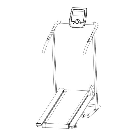
Page 5: Overview Drawing
OVERVIEW DRAWING 47 65 53 60 50 54 57 17L 19... -
Page 6: Parts List
PARTS LIST Description Qty No. Description 001 Rear Roller Ø60x395 1 028 Transport Wheel Ø50 002 Running Deck 1020x407x12 1 029 Spring Washer M8 003 Front Roller Ø60x395 1 030 Adjustable Leveler Extension Sensor Wire III 004 Running Belt 2400x335x1.2 1 031 (180mm) 005 Main Frame... -
Page 7: Hardware Packing List
PARTS LIST Description Qty No. Description Computer Bracket Foam Grip 055 Washer M6 8 061 Ø23x3Tx390 Handlebar Foam Grip 056 Spring Washer M6 6 062 Ø23x3Tx580 057 Nylon Nut M8 6 063 Screw ST4x12 058 Screw ST3x12 2 064 Cap Nut M8 059 Curve Washer M8 4 065 Washer M8 060 Washer M10... -
Page 8: Assembly Instructions
ASSEMBLY INSTRUCTIONS Tool: Hex Wrench Step 1 Attach both Left/Right Handlebar Support Tubes (10, 11) onto the Base Frame (7) with four M8x45mm Carriage Bolts (46), four m8 Curve Washers (59), four M8 Spring Washers (29), and four M8 Cap Nuts (64). Tighten cap nuts with the Hex Wrench provided. NOTE: PLEASE DO NOT FULLY TIGHTEN HARDWARE IN STEP 1 UNTIL STEP 5 IS COMPLETED. - Page 9 Tool: Allen Wrench with Phillips Screwdriver 5M Step 2 Attach the Protective Cover (6) onto the Main Frame (5) with two ST4x12 Screws (63). Tighten screws with the 5M Allen Wrench with Phillips Screwdriver provided. Hardware: (63) Screw ST4x12 2 PCS...
- Page 10 Tool: 60 50 Hex Wrench Allen Wrench with Phillips Screwdriver 5M 54 57 54 57 Allen Wrench 6M Step 3 Lift the front end of Main Frame (5) up by two or more people and then attach the Main Frame (5) onto the Left/Right Handlebar Support Tubes (10, 11) with two M10x55mm Bolts (50) and two M10 Washers (60).
- Page 11 bolt and nylon nut with the 5M Allen Wrench with Phillips Screwdriver and Hex Wrench provided. NOTE: It is recommended that you always use the aid of a second person when assembling the treadmill. Hardware: (50) Bolt M10x55mm (60) Washer M10 2 PCS 2 PCS...
- Page 12 Tool: Allen Wrench with Phillips Screwdriver 5M Step 4 Connect the Hand Pulse Sensor Wire (12) and Extension Sensor Wire III (31) from the Right Handlebar (9) to the Extension Hand Pulse Sensor Wire (35) and Extension Sensor Wire II (34) from the Computer Bracket (14).
- Page 13 Tool: Allen Wrench with Phillips Screwdriver 5M Step 5 Connect the Extension Sensor Wire I (33) from the Right Handlebar Support Tube (11) to the Extension Sensor Wire III (31) from the Right Handlebar (9). Attach both Left/Right Handlebars (8, 9) onto both Left/Right Handlebar Support Tubes (10, 11) with two Handlebar Adorners (13) and two M8x45mm Bolts (45).
- Page 14 Tool: Allen Wrench with Phillips Screwdriver 5M Step 6 Remove two M5x10mm Bolts (52) from back of the Computer (15). Remove bolts with the 5M Allen Wrench with Phillips Screwdriver provided. Connect the Extension Sensor Wire II (34) and Extension Hand Pulse Sensor Wires (35) to the wires that come from the Computer (15).
-
Page 15: Operating The Computer
OPERATING THE COMPUTER SPECIFICATIONS: TMR (TIMER) ---------------------------------- 0:00-99:59 MIN: SEC SPD (SPEED) --------------------------------- 0.0-999.9 KM/H DIS (DISTANCE) ----------------------------- 0.0-999.9 KM CAL (CALORIES) ----------------------------- 0.0-999.9 KCAL ODO (ODOMETER) ------------------------- 0-9999 KM RPM --------------------------------------------- 0-9999 REVOLUTIONS/MIN P (PULSE) ------------------------------------- 40-239 BEATS/MIN USING YOUR COMPUTER The computer can be activated by pressing the buttons or by pedaling. - Page 16 DIS (DISTANCE): Displays the accumulative distance traveled during workout. You may also pre-set target distance in STOP mode before training. To set DIS (DISTANCE) press the MODE button until you see the DIS on the screen. Press the SET button, DIS begin blinking.
-
Page 17: Lifting Up And Setting Down The Treadmill
LIFTING UP AND SETTING DOWN THE TREADMILL LIFTING UP THE TREADMILL To lift up the treadmill, place one hand on the back end of the treadmill and the other hand to pull the Spring Knob. Carefully lift the end of the treadmill up into the upright position until the Spring Knob "pops"... -
Page 18: Adjustments
ADJUSTMENTS Adjusting the Incline Adjuster There are 2 incline angles that the incline adjuster can be set to. Place one hand on the rear end of the Main Frame, then lift the rear end of the Main Frame up and use the other hand to remove the Locking Pin. -
Page 19: Maintenance
MAINTENANCE Cleaning The manual treadmill can be cleaned with a soft clean damp cloth. Do not use abrasives or solvents on plastic parts. Please wipe your perspiration off the manual treadmill after each use. Be careful not get excessive moisture on the computer display panel as this might cause an electrical hazard or electronics to fail. -
Page 20: Warm Up And Cool Down Routine
WARM UP AND COOL DOWN ROUTINE The WARM-UP is an important part of any workout. The purpose of warming up is to prepare your body for exercise and to minimize injuries. Warm up for two to five minutes before aerobic exercising. It should begin every session to prepare your body for more strenuous exercise by heating up and stretching your muscles, increasing your circulation and pulse rate, and delivering more oxygen to your muscles. - Page 21 QUADRICEPS STRETCH With one hand against a wall for balance, reach behind you and pull your right foot up. Bring your heel as close to your buttocks as possible. Hold for 15 counts and repeat with left foot. INNER THIGH STRETCH Sit with the soles of your feet together and your knees pointing outward.
Need help?
Do you have a question about the 40215 and is the answer not in the manual?
Questions and answers