Table of Contents
Advertisement
Quick Links
Download this manual
See also:
Installation Manual
Advertisement
Table of Contents

Subscribe to Our Youtube Channel
Related Manuals for GE Legend


Summary of Contents for GE Legend
- Page 1 Security Legend Installation Manual...
- Page 2 Trademarks and patents Legend product and logo are trademarks of GE Security. GE and the GE monogram are registered trademarks of General Electric. Other trade names used in this document may be trademarks or registered trademarks of the manufacturers or vendors of the respective products.
-
Page 3: Table Of Contents
Troubleshooting your Legend dome ........ - Page 4 Legend Installation Manual Cleaning the bubble............... 29 Spare parts list.
-
Page 5: Preface
Preface This is the GE Legend Installation Manual. It provides an overview of the product and detailed instructions explaining how to install all models. There is also information describing how to contact technical support if you have questions or concerns. For programming and operation instructions, refer to the Legend User Manual. -
Page 6: Introduction
Installation Manual Introduction The installation of domes has been made much easier with many of Legend's innovations. All coaxial and UTP connections are built into the housing, and programming and addressing are site-tied to the housing. Site-tied memory allows you to replace cameras or move them between housings without having to reprogram them for each new site, because the camera will operate using the housing memory. -
Page 7: System Requirements
System requirements Operational requirements Legend contains a built-in receiver that decodes Figure 1. Basic system commands originating from a compatible controller keypad. A minimum of one keypad is required for operation. See Figure 1. From the keypad, an EARTH GROUND... -
Page 8: Minimum Load Requirements
Legend Installation Manual Minimum load requirements Table 1 lists the load requirements for all Legend dome configurations. For safety, the mounting surface, hardware, and procedure used for securing the dome must support the CAUTION CAUTION weight of the dome, mount (if used), cables, and any structural or environmental vibration according to local codes. -
Page 9: Cable Management
Cable management Follow all local codes for cable management. As a general rule, you can fill a cable conduit to a maximum of 60% of its capacity. You must maintain 40% free space. A variety of factors will determine how many cables you can run into the dome. -
Page 10: Power Requirements
Legend Installation Manual Power requirements All Legend domes require a 24 VAC power supply to operate the domes’ PTZ, camera, and heater/blower (if present). The start-up and running power requirements vary depending on the model (Table 3). Table 3. Power requirements at 24 VAC (±4 VAC) operating voltage... -
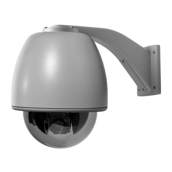
Page 11: Installing The Housing And Cables
Installing the housing and cables There are three basic mounting styles: pendant, wall, and flush. A pendant-mount lowers a dome from a ceiling, a wall-mount extends a dome from a wall, and a flush-mount raises a dome’s bubble even with a ceiling. -
Page 12: Installing The Housing
Legend Installation Manual Figure 5. Preparing the mounting surface for flush-mount housings being mounted into solid surfaces not requiring reinforcement Cutout size: 8 3/8 to 8 7/16 in. Position and size marked (21.27 to 21.42 cm) Installing the housing With the surface prepared and/or the mount now installed, install the housing. - Page 13 Figure 6. Installing the flush-mount housing Building superstructure Safety cable Housing tabs (3) (screwed open and down against the mount or ceiling) 3/4 in. conduit knockouts (2) Ceiling ring Angle brackets (2) Ceiling Nipple Cables fed (snipped off to access through mount the safety cable clip, and housing...
-
Page 14: Pendant-Mount Housings
Legend Installation Manual Pendant-mount housings Pendant-mount housings can be mounted to a pipe to lower them from a ceiling or to a wall-mount arm to extend them from a wall. Instructions are provided in this document for both mounting methods. -
Page 15: Installing The Housing
Installing the housing With the pipe or mount now installed, install the housing. Avoid getting rain or moisture in the housing so that the electronic components on the PCBs are not damaged. CAUTION CAUTION To install the housing to a pipe or mount, see Figure 7 on page 12 and do the following: 1. - Page 16 Legend Installation Manual Figure 7. Installing the pendant-mount housing Typical pipe-mount Ceiling Ceiling Water-sealing rubber boot Water-sealing rubber boot (for outdoor applications) (for outdoor applications) Soapy water Teflon tape Teflon tape applied to sprayed on pipe threads after the pipe before the boot is slid up.
-
Page 17: Preparing The Cables
Preparing the cables Which and how many cables you will be preparing depends upon whether you are setting up your dome to transmit video via its coaxial or UTP source, how many alarms and relays you are connecting in addition to the video, data, and power cables, and if you will be installing an Ethernet cable for flash upgrades. -
Page 18: Wiring And Addressing The Dome
Legend Installation Manual Wiring and addressing the dome For basic operation, you will be connecting data, video, and power cables to the dome. For advanced operation, you can also connect any combination of Ethernet, alarm, or relay cables to the dome. How many cables you will be feeding into the housing depends upon how many alarms and relays you are connecting in addition to the video, data, and power cables, and if you will be installing an Ethernet cable for flash upgrades. -
Page 19: Wiring The Housing Board
Use the provided 2-pin power terminal block. If you are using a heavier gauge cable, ensure that it is properly seated in the connector. Power in the Legend domes is not polarity sensitive. -
Page 20: Power Connections
Legend Installation Manual Figure 10. Connecting the data, video, power, and alarm/relay cables Note: You can also connect the Ethernet cable to flash software upgrades to the dome (see Figure 11 on page 17). Data connections Video connections For data, you have the choice of connecting UTP for RS-422 For video, you have the choice of connecting UTP or or connecting STP for RS-485. - Page 21 Figure 11. Completed wiring in housings Front of housing PTZ clearance notch (indicates front of housing) Note: Route cables away from heaters (if present). Upper bracket Housing ring (plastic pendant) Plastic pendant housing Heaters (2) HEATER Alignment tabs THERMOSTAT HEATER/BLOWER POWER (2;...
-
Page 22: Addressing The Camera Site And Setting The Protocol
Legend Installation Manual Addressing the camera site and setting the protocol The dome provides rotary switches for setting the camera’s site address and communication protocol. Site addresses can be numbered from 0 to 1599. To set the camera’s site address and protocol, see Figure 12 and Table 5 and do the following: 1. -
Page 23: Setting The Termination
Table 5. Equivalent values for the characters on the rotary switches Protocol switch 100s switch 10s switch 1s switch Switch Value Switch Value Switch Value Switch Value ASCII @ 9600 baud Pelco D @ 2400 baud Ultrak @ 9600 baud (even parity) Factory use only Factory use only For future use... -
Page 24: Installing The Camera Assembly
Legend Installation Manual Installing the camera assembly Most people can install the camera assembly with one hand. If you need to use two hands, do so. After installation, there is a pause for about 30 seconds, then the drive mechanism performs a PTZ self-test and initializes. - Page 25 Figure 15. Installing the camera assembly Alignment tabs (2): One is orange on the inside and mates with the orange alignment slot, and one is white on the inside and mates with the white alignment slot. Upper bracket Standoff posts (3) Interconnect card socket Pawl...
-
Page 26: Installing The Bubble
Legend Installation Manual Installing the bubble There are a variety of bubbles and housings. The interlocking clips and safety cables may vary, but all bubbles have them. To prevent damage, do not touch the bubble with your bare hands, do not place the bubble face down on... - Page 27 Figure 16. Attaching the bubble to the housing (cameras not shown to show safety clips clearly) Flush-mount housing Plastic pendant-mount housing Flush-mount housing and bubble ring Plastic pendant-mount housing and bubble ring and bubble ring and bubble ring Cameras not shown in diagrams so that safety clips are clearly visible.
-
Page 28: Turning On The Passcodes
Legend Installation Manual Turning on the passcodes The last task of installing the dome is turning on the passcodes, if desired, before going to the user manual to program the dome. The passcodes control who has access to the features of your dome. Only the installer through the installer passcode has permission to turn on, turn off, or change the passcodes. - Page 29 Figure 24. First screen of programming interface when passcodes are upon initial installation you can directly turned off access the programming interface without a passcode. Note: For complete instructions for navigating and programming the programming interface, refer to the Legend User Manual (1052027).
- Page 30 Legend Installation Manual 7. Turn on the desired passcodes: Figure 25. Passcode screen of the programming interface a. Select Setup and Passcode. b. Select the ab (keyboard) icon next to the Installer passcode. c. Select the digits for a unique passcode.
-
Page 31: Troubleshooting, Maintenance, Support
Troubleshooting, maintenance, support This section provides information to help you diagnose and solve various problems that may arise while configuring or using your GE Security product and offers technical support contacts in case you need assistance. (See Contacting technical support on page 31.) -
Page 32: Common Installation Issues
Note: For programming and operating issues, refer to the Legend User Manual (1052027) and the user manual for your controller keypad. Is the dome resetting during power-up, not powering up at all, or powering up but not operating as expected? Verify that you are supplying sufficient power for your model of dome. -
Page 33: Maintenance
Maintenance Resetting the dome You can reset the dome whether or not you have valid communication between the keypad and the dome. To reset the dome, cycle the power to the dome by turning the power off then on. Rebooting the dome If you have valid communication between the keypad and the dome, then you can reboot the dome. -
Page 34: Spare Parts List
Legend Installation Manual Cleaning the interior of the bubble To clean the interior of the bubble: • To remove dust and other surface contaminants, first use clean, dry, pressurized air to gently blow off loose material. • To remove heavier contaminants, rinse the bubble with water and immediately dry it with clean, dry, pressurized air to prevent water spots. -
Page 35: Contacting Technical Support
Many GE Security documents are provided as PDFs (portable document format). To read these documents, you will need Adobe Acrobat Reader, which can be downloaded free from Adobe’s website at www.adobe.com. -
Page 36: Appendix. Installing The Individual Mounts
Legend Installation Manual Appendix. Installing the individual mounts All mounts (arms, adapters, and brackets) are shipped with installation instructions. This manual provides the installation instructions for only those mounts that are shipped with dome kits, which includes the wall-mount arm and the T-bar support kit. - Page 37 3. Remove the access cover. Figure 30. Removing the access cover 4. Using the arm as a template, place it level Figure 31. Marking the mounting and cable entry holes against the mounting surface and mark the position of the mounting holes, and if needed, the cable entry hole.
- Page 38 Legend Installation Manual 7. Securely fasten the arm to the mounting Figure 32. Fastening the arm to the mounting surface surface with the appropriate fasteners. Again, ensure that it is level. See Table 1, Minimum load requirements of dome con- 8.
-
Page 39: Opening A Conduit Hole
Opening a conduit hole Open the conduit hole for a 3/4 in. or 1/2 in. conduit connector, if you need to bring the facility cables in through the side of the arm. See Figure 35 and do the following: 1. Locate the dimple on the side of the arm. Figure 35. -
Page 40: Installing The T-Bar Ceiling Support Kit
Legend Installation Manual Figure 36. Parts of a supported T-bar ceiling Angle brackets (provided with kit) Ceiling ring (provided with kit) Ceiling T-bars Removable ceiling panel Installing the T-bar ceiling support kit One side of the ceiling ring is flat. The other side has two press nuts. Orient the ceiling ring as directed in the instructions. - Page 41 3. Using the ceiling ring as a template, mark the Figure 38. Marking the mounting holes and housing pass-through hole position of the center mounting holes and the housing pass-through hole on the removable ceiling panel. Housing pass-through 4. Following all local codes, drill the mounting holes (use a 3/16 in. drill bit) and cut the housing pass- through hole.
- Page 42 Legend Installation Manual 7. Using the last four of the fasteners provided, Figure 40. Installed T-bar support kit fasten the ends of the angle brackets to the End mounting holes of ceiling panel. the angle brackets 8. Reinstall the panel in the ceiling.
- Page 43 Index addressing ....................18 passcodes ....................24 pendant-mount housing................10 power cable size and length requirements ............6 requirements..................6 bubble......................22 product contents....................2 description ....................2 protocol ....................18 cable publication library...................31 management..................5 preparation..................13 requirements..................4 camera assembly ..................20 cleaning the bubble .................29 rebooting the dome .................29 conventions ....................1 references ....................1 requirements cable .....................4...
Need help?
Do you have a question about the Legend and is the answer not in the manual?
Questions and answers