Table of Contents
Advertisement
Quick Links
Advertisement
Table of Contents

Subscribe to Our Youtube Channel
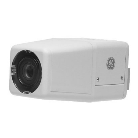
Summary of Contents for GE KTC-117V3, KTC-117V9
- Page 1 KTC-117V3/117V9 KTC-217CV3/217CV9 KTC-247CEV3/247CEV9 Cameras...
- Page 2 © 2003 Kalatel, a GE Interlogix company All Rights Reserved. Any GE Interlogix, Kalatel division, software supplied with GE Interlogix, Kalatel division, products is proprietary and furnished under license and can be used or copied only in accordance with the terms of such license.
-
Page 3: Table Of Contents
KTC-117/217/247 User Manual ABLE OF ONTENTS EFORE EGIN NTRODUCTION AMERA ROGRAMMING THE 3.1 B ACKLIGHT 3.2 F LICKER 3.3 W HITE ALANCE 3.4 V ORMAL OR 3.5 Z ORMAL OR NSTALLING THE 4.1 M OUNTING THE 4.2 A TTACHING THE 4.3 A DJUSTING THE AKING... -
Page 4: Before You Begin
For assistance in installing, operating, maintaining, and troubleshooting this product, refer to this document and any other documentation provided. If you still have questions, contact Kalatel Technical Support: GE Interlogix, Kalatel division Call: 800-469-1676 Fax: 541-752-9096 Note: You should be at the equipment, ready with details before calling Technical Support. -
Page 5: Introduction
KTC-117/217/247 User Manual NTRODUCTION The KTC-117/217/247 cameras come in an all-in-one package that includes the components shown in Figure 1. 24 VAC Mounting hardware Camera and BNC connectors Figure 1. Package contents See Table 1 for the camera models and their descriptions. Table 1. -
Page 6: Back Panel
Camera Back Panel AMERA See Figure 2 when performing the camera setup and adjustment procedures. DIP switch Terminal block Figure 2. Camera back panel ANEL Direct drive auto iris level adjuster Power LED KTC-117/217/247 User Manual Video out 1041075C / November 2003... -
Page 7: Dip Witch
KTC-117/217/247 User Manual ROGRAMMING THE To program the DIP switch (Figure 2), refer to Figure 3 or Figure 4 depending on your camera model. Figure 3. DIP switch for KTC-117 cameras Figure 4. DIP switch for KTC-217 and KTC-247 cameras ACKLIGHT Backlight compensation controls iris gain and white balance simultaneously. -
Page 8: (Atw Or Fix)
Programming the DIP Switch HITE ALANCE Note: This switch is not available for the KTC-117 cameras • Auto-tracking white balance (ATW) mode In the ATW mode, the range of colors in the scene being monitored is tracked continuously, and the white balance is set automatically by an internal micro-controller. -
Page 9: Racket And Camera
KTC-117/217/247 User Manual NSTALLING THE You can mount the camera on a vertical surface (Figure 5), and below (Figure 6) or above (Figure 7) a horizontal surface. Figure 5. Mounting on a vertical surface Figure 6. Mounting below a horizontal surface To mount the bracket see section 4.1. -
Page 10: Mounting The Bracket
Installing the Bracket and Camera OUNTING THE Unscrew the mounting plate (Figure 8) from the rest of the bracket. Place the mounting plate against the vertical or horizontal mounting surface and mark the location of the three mounting holes. Note: The camera comes with fasteners and anchors;... -
Page 11: Camera To The Bracket
KTC-117/217/247 User Manual TTACHING THE Turn the wing nut (Figure 8) on the bracket counterclockwise to free the ball and socket bolt (Figure 8). See Figure 11. Screw the ball and socket bolt into the bracket hole in the top or bottom of the camera. -
Page 12: Camera Angle.
Installing the Bracket and Camera DJUSTING THE If necessary, turn the wing nut (Figure 8) on the bracket counterclockwise to free the ball and socket bolt (Figure 8). See Figure 11. Swivel the camera on the ball and socket bolt to adjust the camera angle. -
Page 13: Making Cable Connections
KTC-117/217/247 User Manual AKING Note: This camera is 24 VAC only. See Figure 15 and perform the following. 24 VAC power source Figure 15. Power and video connections Attach the provided BNC connectors to the ends of the video cable. Connect the video cable to the monitor’s video in BNC connector. - Page 14 Making Cable Connections Loosen the ~AC24V terminal connectors on the terminal block and connect the power cable to them. Tighten the terminal connector screws until snug, ensuring that the power leads are secure. Connect the other end of the power cable to the power supply unit and tighten the connector screws until snug.
-
Page 15: Camera Adjustments
KTC-117/217/247 User Manual AKING To open the housing see section 6.1. To adjust the camera focus see section 6.2. To make direct drive auto iris level adjustments see section 6.3. PENING THE See Figure 16 and Figure 17 and perform the following. Grip strips Door... -
Page 16: Direct Drive Level
Making Camera Adjustments DJUSTING THE See Figure 18 and perform the following. Figure 18. Adjusting the camera focus Loosen the zoom ring thumbscrew. Turn the zoom ring to set the desired zoom. Tighten the zoom ring thumbscrew. Loosen the focus ring thumbscrew. Turn the focus ring to set the desired focus.


Need help?
Do you have a question about the KTC-117V3, KTC-117V9 and is the answer not in the manual?
Questions and answers