Table of Contents
Advertisement
Advertisement
Table of Contents

Subscribe to Our Youtube Channel
Related Manuals for Sole Diesel MINI 17


Summary of Contents for Sole Diesel MINI 17
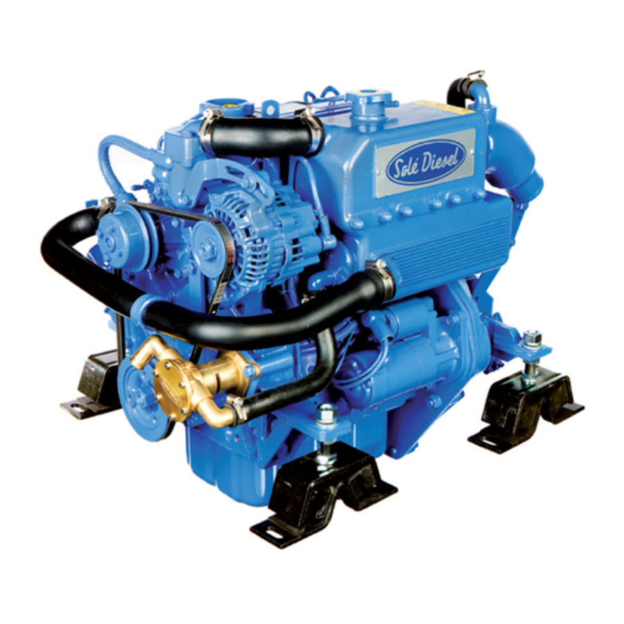
- Page 1 ENGINE INSTRUCTIONS MANUAL MINI 17, MINI 26, MINI 29 MINI 33, MINI 44, MINI 55...
-
Page 3: Importance Of The Manual
0. INTRODUCTION 0.0 FOREWORD Dear client: The SOLÉ S.A. engine you have purchased is a product of the highest technological quality Our Service SOLÉ DIESEL department has recently been strengthened to ensure even better service for all our clients. Reliable duty and long life of the engine you have purchased can only be guaranteed if you use exclusively original spare parts and ensure that the unit is serviced by our specialized personnel. - Page 4 0.1.4 SYMBOLS IN THE MANUAL The Safety symbols and notices shown below are used throughout this publication to draw the user’s attention to situations or hazardous procedures that could damage the engine or cause personal injury, and to indicate suitable practices to assure the correct operation of the engine.
-
Page 5: General Information
1. GENERAL INFORMATION 1.1 ENGINE MANUFACTURER’SIDENTIFICATION DATA MANUFACTURER: Mounting order Number SOLÉ, S.A. Ctra. de Martorell a Gelida, km 2 08760 MARTORELL (BARCELONA) SPAIN MODEL: _____________________________ TRADE DESIGNATION: Fig. 1.1 MINI-17 MINI-26 MINI-33 MINI-44 MINI-55 ______________________________ Fig. 1.2 The above data can be quickly identified in the following position: - Engine nameplate showing identification data (see Fig. - Page 6 Before starting work the operator must be aware of the position and operation of all commands and the characteristics of the engine; make a daily check of the safety devices on the engine. Disabling or tampering with the safety devices on the engine is strictly prohibited.
- Page 7 Cooling: liquid cooled circulation controlled by centrifugal pump with thermostatic control and heat exchanger. Cooled exhaust collector. Injection pump: BOSCH type. Lubrication: forced-feed lubrication by gear-pump(Mini 17 – 26 - 29). Forced-feed lubrication by trochoid pump (Mini 33 – 44 – 55). Electrical system: 12V.
- Page 8 / 3000-3600 rpm = 3 - 4 kg/cm (2) Oil pump (3) Oil filter (4) Oil pressure switch ENGINE TYPE: CIRCUIT (5) Oil strainer CAPACITY(LITRES) (6) Drain plug MINI 17 2,40 MINI 26 3,60 MINI-29 4,20 MINI 33 3,70 MINI 44/55 5,50 2.3.2 GEARBOX...
-
Page 9: Injection Pump
(1) Fuel injection nozzle (2) Fuel injection pipe (3) Fuel leak - off pipe (4) Injection pump Model Quantity (5) Priming pump. See the picture 2.4 for engines equiped with MINI-17 mechanical priming puma (Ronim-V and SMI-R2 and SMI-R3 MINI-26/29/33 gerarboxes). - Page 10 2.6 TECHNICAL SPECIFICATIONS. UNITS MINI-17 MINI-26 MINI-29 MINI-33 MINI-44 MINI-55 Cylinders number Bore Stroke Total desplacement c.c. 1318 1758 1758 Compression ratio 23:1 23:1 22:1 22:1 22:1 22:1 Min. Ilding speed r.p.m. Max engine speed r.p.m. 3600 3600 3600 3000 3000 3000 Standard reducer gearbox...
-
Page 11: Engine Dimensions
2.6.1 ENGINE DIMENSIONS MINI-17/26 + RONIM-V MINI-17/26 + TMC40 (all versions) RONIM-V TMC-40 MINI-17 295 mm 634 mm 295 mm 615 mm MINI-26 384 mm 723 mm 384 mm 704 mm ENG - 9 03917700.ENG rev. 0... - Page 12 (all types of TMC40) MINI-29 + TMC40 MINI-29 + TTMC35A2 ENG - 10 03917700.ENG rev. 0...
- Page 13 MINI-33 + RONIM-V MINI-33 + TMC40 (all versions) MINI-33 + TTMC35A2 ENG - 11 03917700.ENG rev. 0...
- Page 14 MINI-44 + SMIR3 MINI-44 + TTMC35P MINI-44 + TTMC35A2 ENG - 12 03917700.ENG rev. 0...
- Page 15 MINI-55 + TTMC35P 2.7 GEARBOX The mechanically driven (RONIM-V, SMI-R2 and SMI-R3) gearbox is made with high mechanical and seawater resistance grey castiron alloy. Operation: With engine at idle speed, smoothly push forwardly the inverter lever (forward gear) and rearwardly (rear gear) according to the sense wanted.
-
Page 16: Transport, Handling, Storage
3. TRANSPORT, HANDLING, STORAGE 3.0 GENERAL WARNINGS Refer to heading 1.3 for safety information. 3.1 PACKING AND UNPACKING The engine is shipped in various types of packing systems: STORAGE STACKING OF PACKS: Pallet with wooden crate (See heading covered area only. Max. -
Page 17: Packing List
3.2.1 PACKING LIST (1) ASSEMBLED ENGINE (2) TECHNICAL DOCUMENTATION the technical documentation contains: instruction and user manual. Packing material must be disposed of in compilance with established law in the user’s country. Packing materials: Wood Steel nails Steel screws Plastic film Cardboard Metal or plastic straps 3.3 TRANSPORT AND HANDLING THE PACKED ENGINE When lifting and transporting the engine use EXCLUSIVELLY a fork lift or bridge crane of appropiate load capacity, with chains equipped with safety hooks suitable for lifting the load in question. -
Page 18: Installation
4. INSTALLATION 4.0 GENERAL WARNINGS Refer to heading 1.3 for safety information. 4.1 ASSEMBLY DATA (kgf · m) TIGHTENING VALUES MINI-17 / 26 MINI-29 MINI-33 / 44 MINI-55 M14 Cylinder head bolts M12 Cylinder head bolts M10 Cylinder head bolts 7.5 –... -
Page 19: Changing Engine Sump Oil
4.2 ENGINE SUPPLIES 4.2.1 CHANGING OIL 4.2.1.1 CHANGING ENGINE SUMP OIL Use oil that corresponds to the technical specifications in chapter 9. Oil shall be changed with a hot engine so as to be sure the oil is fully drained. This is done by removing the stopper and mounting the drain pump. -
Page 20: Filling The Cooling Circuit
warning: the use of oil that does not conform to the technical specifications on chapter 9 will cause serious damage to the engine and invalidate the guarantee. when supplying the engine never ingest oil, fuel, coolant liquid, etc.. these substances are harmful to the personal health of the user if ingested 4.2.2 FILLING THE COOLING CIRCUIT As a refrigerating liquid, an anti-freeze of the brand KRAFFT ACU... -
Page 21: Indications For Removal / Disposalof Waste Material
4.2.3 REFUELING Always use clean, filtered gas oil. Never use either kerosene or heavy oils. On topping up with fuel, use a funnel with a metallic mesh filter, to keep out impurities or foreign bodies which may cause problems in the fuel injection circuit. Whenever possible, keep the fuel tank full, as temperature changes may cause condensation of the damp air present in the tank so that water accumulates at the bottom, giving rise to corrosion or making it impossible to start the engine if this is aspirated by the fuel pump. -
Page 22: Preparing The Engine For Use
5. PREPARING THE ENGINE FOR USE 5.0 GENERAL WARNINGS Refer to heading 1.3 for safety information. 5.1 INSTRUCTIONS FOR FIRST STARTING Do not alter the functioning conditions of the engine by changing the settings of factory sealed parts. Tampering with such parts automatically invalidates the guarantee. -
Page 23: No-Load Running Test
(g) OTHER CHECKINGS (g.a) Carefully check the engine positioning points. (g.b) Check all screws are correctly tightened. (g.c) Check all water, oil and gas-oil pipe nipples, verifying if all them are well connected and correctly tightened. (g.d) Check exhaust and transmission systems. 5.1.1 BLEEDING AIR FROM THE FUEL SUPPLY SYSTEM On the first start-up of the engine, and if this has operated with the fuel tank empty, air may enter the feed system, and it is... -
Page 24: Using The Engine
6. USING THE ENGINE 6.0 GENERAL WARNINGS Refer to heading 1.3 for safety information. 6.1 STARTING THE ENGINE For MINI-17/26/29/33/44/55 engines STARTING THE ENGINE Place control lever at the neutral point. Rotate the ignition key to position “ON” Check oil pressure, battery charge lamps are lighted and the alarm is heard (refer to heading 2.5.1 for lamps position). -
Page 25: Stopping The Engine
For MINI-17/26/29/33/44/55 engines STOPPING THE ENGINE Allow to run at low speed for 4 or 5 minutes and place the gearbox remote control lever in the neutral position. Turn the starter key to “STOP” And mantain this position until the engine is fully stopped. With the engine stopped the starter key returns to “OFF”... -
Page 26: Long Inactivity Instructions
6.5 CONSERVATION warning! All engines not in use are subject to rusting and corrosionof machined surfaces that are not protected with a paint coating. The degree of corrosion depends on meteoro logical changes and climatic conditions. The following recommendations are therefore of a general nature but they will help prevent orreduce the risk of damage due torusting 6.6 LONG INACTIVITY INSTRUCTIONS When the engine is not to be used for a long period of time or during the winter time, certain operations must be carried out to keep it in perfect operationing condition. -
Page 27: Repair And Maintenance
7. REPAIR AND MAINTENANCE 7.0 GENERAL WARNINGS Refer to heading 1.3 for safety information. 7.1 TYPE AND FREQUENCY OF INSPECTIONSAND MAINTENANCE INTERVENTIONS INCREASE THE FREQUENCY OFMAINTENANCE IN HARSH DUTYCONDITIONS. (FREQUENT STOPSAND STARTS, DUSTYSURROUNDINGS, PROLONGEDWINTER SEASON, NO-LOADRUNNING) IF POSSIBLE CHECK LEVELS ANDREPLENISH SUPPLIES WITH THEENGINE STOPPED AND ATAMBIENT TEMPERATURE WARNING! RISK OF BURNS DURINGMAINTENANCE OPERATIONSCARRIED OUT WHEN THE ENGINEIS HOT. - Page 28 INTERVALOS Inspection concept Daily 1ª 50 Cada 200 Cada 400 Cada 800 Every 2 hour hour hour hour years Electrical system Every instrument Incandescent spark plug Alternator and starting motor Alternator belt and tension Battery level Cleaning Inspection, adjustment or filling Change Drainage DAILY CHECKING BEFORE USE OF THE ENGINE...
-
Page 29: Operating Description
7.2 OPERATING DESCRIPTION Change engine and gearbox oil: See heading 4.2.1. Change oil filter (Fig. 7.1): The oil filter is located under the air filter. Change the oil filter after the firsts 50 operating hours and afterwards every 200 hours. The oil filter being a cartridge type of easy handling shall not be cleaned. -
Page 30: Water Filter Cleaning
Water filter cleaning: It is important to fit between the engine and the bottomcock a filter to avoid that any imputities existing in these a water might clog the cooling conducts. Filter shall be cleaned every 200 hours by loosening the wing nut and removing the filtering component. - Page 31 Fuel decanting filter drainage ( optional ): Loosen the wing nut (3) (Fig. 7.6) located at the lower side of the glass vessel and let go all the acrued water. Shut again off the wing nut and check it does not drip. Replace the fuel filter element (engine): The fuel filter is bladded and cannot be cleaned.
- Page 32 (13) Check condition of sea water pump impeller and its eventual replacement: Driving impeller is neoprene and cannot rotate dried. If operated without water, the impeller can be broken. It is important therefore that a spare impeller is always available. To change the impeller, close water inlet cock, remove pump cover and with two screwdrivers prize it by removing the impeller from the shaft.
- Page 33 (18) Inspect injection pump: The fuel injection pump is one of the most relevant components of a diesel engine and therefore its handling requires the best care. In addition, the injection pump has carefully been adjusted at factory and should never be adjusted carelesly. Said adjustment, whenever is required, shall be made by a SOLÉ...
-
Page 34: Troubleshootings
7.3 TROUBLE SHOOTINGS ENGINE FAILURE PROBABLES CAUSES FAILURE TO START C1 – C2 – C3 – C4 – C5 – C6 – C9 – E1 – E2 – E3 – E4 – E5 M3 – R1 – R3 – L4 STARTS THEN STOPS C1 –... -
Page 35: Additional Instructions
8. ADDITIONAL INSTRUCTIONS 8.0 ADDITIONAL INSTRUCTIONS Refer to heading 1.3 for safety information 8.1 INSTRUCTIONS FOR DECOMMISSIONING, SCRAPPING AND DISPOSAL When you decide to decommission the engine, please contact SOLÉ S.A., we will provide you with the relevant instructions in relation to the laws in force at the time. - Page 36 If the air deviates from these values, correction factors (in %) are found in the graphs below. Use the correction factors in “calculation of engine output” Temperature (ºC) Air Pressure (mbar) Graph 3 Graph 4 Effect of intake air temperature on engine output. Effect of air pressure on engine output.
-
Page 37: Technical Annexes
For mechanical geared RONIM-V and SMI-R2 and SMI-R3 gearboxes, it is recommended to use the same type of oil that is used in the engine, a Sole Diesel SAE 15W/ 40, excepting the following models indicated in the table below. -
Page 38: Engine Inclination
9.2 OIL DIPSTICK MODIFICATION WHEN THE ENGINE IS FITTED INCLINED. When the engine is fitted inclined, the oil dipstick must be modificated to avoid problems of aspiration by the oil pump. See the table enclosed for modification level in rod oil. Increase level D or decrease the level E, starting off of level H of the original oil dipstick. - Page 40 MARINE DIESEL ENGINES SOLÉ S.A. Dpto. Publicaciones Técnicas Ctra. Martorell a Gelida km. 2 08760 Martorell Barcelona - Spain Tel. (+34) 93 775 14 00 Fax. (+34) 93 775 30 13 e-mail: sole@solediesel.com www.solediesel.com Ref. 03917700.ENG Ed. 1 rev. 0...
Need help?
Do you have a question about the MINI 17 and is the answer not in the manual?
Questions and answers