
Related Manuals for Sole Diesel MINI-17


Summary of Contents for Sole Diesel MINI-17
- Page 1 Solé Diesel, S.A. C-24 Manual Marine diesel engines Operator’s manual MINI-17 MINI-29 MINI-33 MINI-44 MINI-55 U_MIB3_EN Revision 1...
-
Page 3: Introduction
Introduction Introduction Presentation Dear Customer, First of all, we would like to thank you for choosing a Solé Diesel product. We recommend that you read this manual carefully before carrying out any of the operations and keep it close at hand, near the engine, as it can be of great use in the future. -
Page 4: Table Of Contents
Table of contents Table of contents Introduction..............................3 Safety precautions and instructions......................6 Solé Diesel warranty ..........................10 Section 1 – Engine information ....................... 13 1.1. Engine Identification ....................... 13 1.2. Engine parts identification...................... 14 Section 2 – Transport, handling and storage ..................15 2.1. - Page 5 Table of contents Maintenance task. Water separator filter purge ........................32 Maintenance task. Fuel filter change ............................ 32 Maintenance task. Injection pump inspection ........................32 Maintenance task. Injector inspection ..........................33 Maintenance task. Bleeding air from the fuel system ......................34 6.6.
-
Page 6: Safety Precautions And Instructions
Safety precautions and instructions Safety precautions and instructions Solé Diesel is concerned for your safety and your machine’s condition. Safety Precautions and Instructions are one of the primary ways to call your attention to the potential hazards associated with our engine operation. Follow the precautions listed throughout the manual before and during operation and maintenance procedures for your safety, the safety of others and the performance of your engine. - Page 7 Safety precautions and instructions Combustible materials. A fire can cause severe injury or death. Engine fuels, fuel vapors and combustible materials are flammable and explosive. Handle these materials carefully to minimize the risk of fire or explosion. Equip the compartment or nearby area with a fully charged fire extinguisher. In case of fire do not open sound shield compartment and follow these instructions: - Shut down engine(s) - Continuously discharge entire contents of a halon or CO2 portable fire extinguisher...
- Page 8 Safety precautions and instructions Before working on the engine or connected equipment, disable the engine as follows: Set the engine controller (SVT) to OFF Mode. (1) Disconnect the power input from battery. (2) Disconnect the battery cables. Remove the negative (-) lead first when disconnecting the battery.
- Page 9 Safety precautions and instructions Engine labels If the engine does not start after several attempts to crank may cause water entering the engine. In this situation it is recommended: Close the seacock. Drain the water from the exhaust system in the water trap.
-
Page 10: Solé Diesel Warranty
Solé Diesel warranty Solé Diesel warranty Read the manual and documents delivered with each engine before carrying out any of the operations or presenting any queries. The engine is supplied without any liquids. Ensure that the liquids used match the specifications contained in Solé Diesel manuals. The application of the conditions described in this document shall only be effective for engines or generator sets that have been invoiced after January 1, 2012. - Page 11 Solé Diesel warranty Restrictions Coverage: a) To validate the warranty is necessary fill and send the inspection prior to the delivery of propulsion engines or genset to Solé Diesel through an official installer. See SECTION 13. b) The warranty covers any failure of the product under normal opera- ting conditions caused by a defect in manufacturing.
- Page 12 Solé Diesel warranty Responsibilities Responsibilities of the manufacturer: The obligations of Solé Diesel are restricted to repairing the defective parts or, IF DEEMED APPROPRIATE BY SOLÉ DIESEL, returning the amount of the purchase or replacing the parts to prevent poor operation resulting from defective materials or faults in the manufacture covered by the warranty. Solé...
-
Page 13: Section 1 - Engine Information
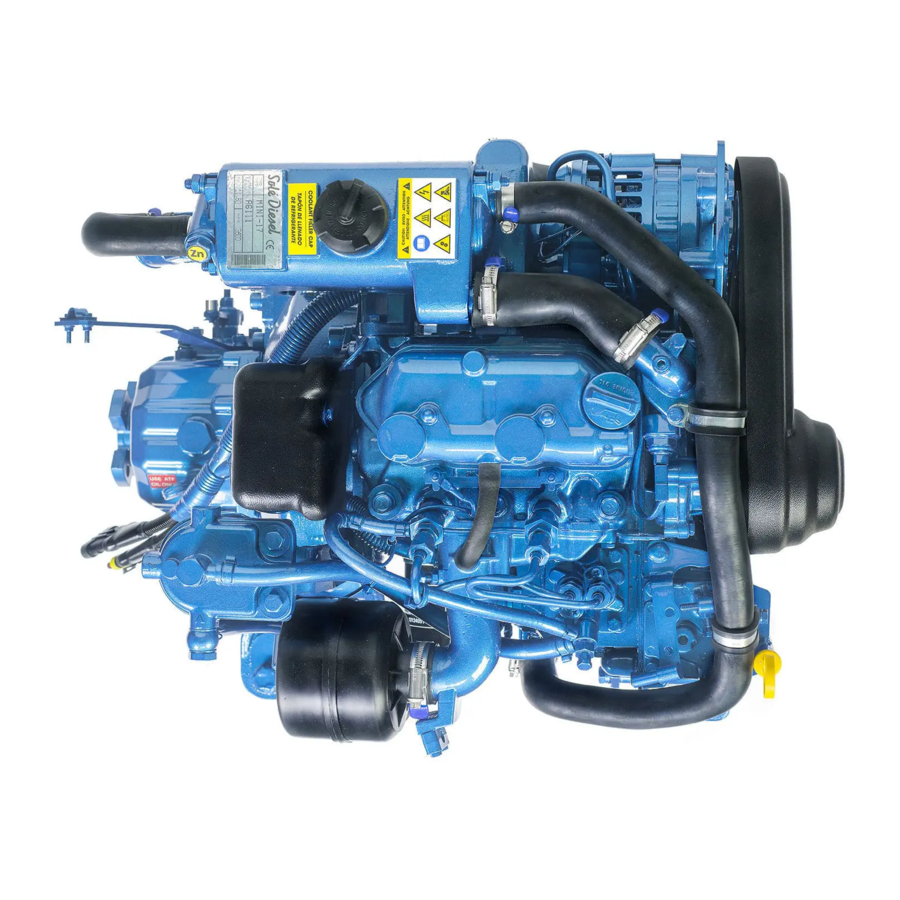
Engine information Section 1 – Engine information 1.1. Engine Identification Identification label: The nameplate is located above the refrigerator, for MINI-17 and MINI-29, and on top of the rocker cover for the MINI-33m MINI-44 and MINI-55. Engine serial number: In addition, all engines are marked with the serial number on the block. -
Page 14: Engine Parts Identification
Engine information 1.2. Engine parts identification PIECE ELEMENT PIECE ELEMENT Air filter Oil filler cap Solenoid switch Alternator Oil filter Cooling system Injection pump Starter Seawater pump Cooling drain plug Bolt engine hanger Gearbox control lever Oil dipstick Fuel pump Turbocharger Fuel filter Relays cover... -
Page 15: Section 2 - Transport, Handling And Storage
Transport, handling and storage Section 2 – Transport, handling and storage 2.1. Reception When the engine is delivered make sure that the packing has not been damaged during transport and that it has not been tampered with or that components inside the packing have been removed (see information marked on covers, bases and cartons). -
Page 16: Transporting And Handling The Unpacked Engine
Transport, handling and storage 2.3. Transporting and handling the unpacked Engine When the engine is unpacked and ready for transport, use EXCLUSIVELY the appropriate lifting eyebolts. 2.4. Storage of packed and unpacked engine If the engine is left idle for prolonged periods, the client must check the possible conditions of conservation in relation to the place of storage. -
Page 17: Section 3 - Installation
3.1. Angle of installation Make sure the engine is installed on a level surface. Otherwise, the following angular operation maximum is permitted: Continuously Temporaly MINI-17 / MINI-29 25º 30º (Max. 30 min.) MINI-33 / MINI-44 / MINI-55 15º 30º (Max. 30 min.) If the engine operates in these conditions, check Section 6.5. -
Page 18: Section 4 - Svt Control Panel
SVT Control Panel Section 4 – SVT Control Panel 4.1. Identification Panel The SVT range consists of a control and protection panel set used with propulsion engines. All units are designed for easy operation by both the installer and the end customer, with different degrees of performance, depending on the model. -
Page 19: Panel Parts
SVT Control Panel 4.2. Panel Parts PRE-HEATING The LED light turns on when the pre-heating spark plugs receive power. It turns off after a few seconds to indicate that the engine is ready for start-up. NOTE: The only purpose of this LED is to inform the user, it does not act on the engine. -
Page 20: Settings
SVT Control Panel 4.3. Settings Tachometer calibration The tachometers supplied with the panel are calibrated in the factory. The user must only calibrate tachometers purchased as spare parts. The tachometer can be calibrated with the switch at the rear. To know its position, the pulley ratio must be calculated. -
Page 21: Section 5 - Operation
Operation Section 5 - Operation 5.1. Prestart checklist Follow these checks and inspections to ensure the correct engine operation. In addition, some checks require verification after unit starts. AIR CLEANER: Check for a clean and installed air cleaner element to prevent unfiltered air from entering the engine. -
Page 22: Stopping Engine
Operation After starting up the engine, check the following points. If you find anything wrong, immediately stop the engine, and then investigate the cause. 1. Lubrication oil pressure should be from 0,29 to 0,39 MPa (3 to 4 kgf/cm2) (2,9 to 3,9 bar) at nominal speed. -
Page 23: Winterization And Preservation
Operation 5. When starting the engine, make sure that the glow plugs become hot enough. 6. If necessary, replace the diesel oil by a specified diesel oil type for low temperatures. The accumulation of impurities in the fuel tank could cause faulty firing. All engines not in use are subject to rusting and corrosion of machined surfaces that are not protected with a paint coating. -
Page 24: Maintenance During The Storage
Operation 5.6. Maintenance during the storage During the long engine storage, it has to be stored inside a ventilated area and free of humidity. When the engine stay stopped for 3 months or more, inside parts can be oxidize and lost the oil film. -
Page 25: Section 6 - Systems And Scheduled Maintenance
Systems and scheduled maintenance Section 6 – Systems and scheduled maintenance 6.1. Safety and prevention Information of special tools required and basic safety precautions. Disassembly: ✓ Use the correct tools and instruments. Serious injury or damage to the engine can result from using the wrong tools and instruments. - Page 26 Systems and scheduled maintenance Intervals 1st 20h- Every Every Every Every Every 2 Winter storage and Inspection Item Daily 200h 400h 800h year years Preservation Screw tightening, fastening. Engine block. General Valve clearance. Exhaust gas, noise and vibrations. Compression pressure. Lubrication Engine oil.
-
Page 27: General
Systems and scheduled maintenance 6.3. General Solé Diesel offers, for these engine models, the several Pack, consult on the web. On board spare parts Reference MINI-17/ MINI-29 v6 17640110 MINI-33 MINI-44 v6 17240304 MINI-55 v6 17740304 Maintenance task. Screw tightening, fastening For details of tightening torques see Section 9 Torques. -
Page 28: Maintenance Task. Compression Pressure Inspection
4. If the compression pressure is lower than repair limit, check the engine parts affected. Máximum pressure Engine Compression pressure Repair limit difference betwen speed cylinders MINI-17 280 rpm 2,7MPa (28 kgf/cm 2.2 MPa (22 kgf/cm 0,25 MPa (2.5 kgf/cm MINI-29 280 rpm 2,7MPa (28 kgf/cm 2.2 MPa (22 kgf/cm... -
Page 29: Lubrication System
Main gallery Oil pump Oil strainer Oil pan Oil filter Pressure relief valve *Oil circuit capacity (l) MINI-17 MINI-29 MINI-33 MINI-44 MINI-55 *Including filter change (0,5l) Oil specifications Use oil with 15W40 viscosity (this is an all-season oil for temperatures ranging between -15ºC and +40ºC) or select the most suitable oil viscosity for... -
Page 30: Maintenance Task. Oil Level Check
H: maximum level that marks the rod L: minimum level that marks the rod E: Adjustment of the maximum level according to the inclination of the motor. It can be a positive or negative measure MINI-17 MINI-29 MINI-33 MINI-44 MINI-55... -
Page 31: Maintenance Task. Oil Fill/Change
Systems and scheduled maintenance Maintenance task. Oil fill/Change Oil must be changed with hot engine so as to be sure the oil is fully drained. The procedure is the following: 1. Drain the oil (follow steps below) a. Stop the engine. b. -
Page 32: Maintenance Task. Fuel Level Inspection
Systems and scheduled maintenance Maintenance task. Fuel level inspection Periodically, it is necessary to check the fuel level to assure the operation of the engine. On top of that, if fuel pump sucks air when the fuel level is lower than pump suction, it could break. Whenever possible, keep the fuel tank full. -
Page 33: Maintenance Task. Injector Inspection
Systems and scheduled maintenance Maintenance task. Injector inspection To check the injection pressure of injectors (opening pressure) you have to follow these steps: 1. Remove nozzle and washer. 2. Install the injection nozzle on the tester. Slowly operate the tester handle full strokes to bleed (remove) air from the pipe and nozzle. -
Page 34: Maintenance Task. Bleeding Air From The Fuel System
Sea water filter Thermostat Sea water pump Heat exchanger Wet exhaust elbow Coolant circuit capacity (l) MINI-17 MINI-29 MINI-33 MINI-44 MINI-55 Solé, S.A. C-243 b, km 2 · 08760 Martorell (Barcelona) ·Tel. +34 93 775 14 00 · www.solediesel.com · info@solediesel.com... -
Page 35: Coolant Specifications
1. Drain off all the coolant by opening the two drain plugs, one in the heat exchanger and the other in the cylinder block. 2. Close the drain plugs. 3. Remove bleeding bolt of thermostat holder (only Mini-17/29). 4. Refill to the hole in the tank cap with coolant. Maintenance task. Seawater filter inspection It is important to install a seawater filter (supplied as accessory) between seawater cock and the seawater pump to avoid that any impurity might clog the seawater circuit or seawater pump. -
Page 36: Maintenance Task. Seawater Pump Impeller Inspection
Systems and scheduled maintenance Maintenance task. Seawater pump impeller inspection Seawater pump impeller is neoprene and cannot rotate dried. If operated without water, the impeller can be broken. It is important therefore that a spare impeller is always available. Impeller inspection and replacement procedure: 1. -
Page 37: Inlet And Exhaust System
Systems and scheduled maintenance 6.7. Inlet and exhaust system Exhaust circuit description There are two possible installations of the exhaust system. You need to check the distance between water injection point and waterline to decide which type of installation you need. This information is specified in the following drawings. -
Page 38: Maintenance Task. Air Filter Inspection
Systems and scheduled maintenance Type 2 installation. When between water injection point of wet exhaust and waterline there is less than 150 mm or the point of injection is below waterline. The wet exhaust is the engine’s standard equipment. If you want dry exhaust, which is an optional equipment, contact with our dealers. -
Page 39: Electrical System
SVT 30. In addition to the option of installing double panel. More information about the panel can be found in the SVT Operator’s Manual ENGINE MODEL REFERENCE MINI-17 / MINI-29 60938130 MINI-33 / MINI-44 / MINI-55 60972130 Battery The minimum recommended battery capacity is 95 Ah. -
Page 40: Relays
Systems and scheduled maintenance Relays The relays of the electrical installation are located inside the electrical protective box where it is shown in the image. The earth isolated motors have bipolar relays, in the images can see the position. Maintenance task. Incandescent glow plug inspection 1. -
Page 41: Maintenance Task. Starter Motor Inspection
Systems and scheduled maintenance Maintenance task. Starter motor inspection STARTER MOTOR: 1. Check if there is any impurity in pinion teeth. 2. Make sure that the pinion shaft turns freely when turned in the direction of driving (clockwise) and it is locked when turned in the opposite direction. -
Page 42: Section 7 - Troubleshooting
Troubleshooting Section 7 - Troubleshooting If a fault occurs in the engine, proceed as follows: ❖ Within the period of warranty • Contact to Solé Diesel Official Service. See SOLÉ DIESEL WARRANTY ❖ Outside the period of warranty • Contact to Solé Diesel Official Service. See SOLÉ DIESEL WARRANTY. •... - Page 43 Troubleshooting ENGINE FAILURE PROBABLE CAUSES RECOMMENDED ACTIONS SECTION Check the pin connections and check that they have Key switch STV PANEL voltage. Electronic board Check that goes voltage electronic board to micro relay. Replace the controller fuse. If the fuse blows again, Blown fuse troubleshoot the controller.
- Page 44 Troubleshooting ENGINE FAILURE PROBABLE CAUSES RECOMMENDED ACTIONS SECTION Fuel filter clogged Change fuel filter. Fuel injectors dirty or faulty Clean, test and/or replace the inoperative fuel injector. FUEL SYSTEM Injection pump incorrectly Contact with our dealer BLACK SMOKE INLET AND EXHAUST Air filter clogged Replace air filter element.
- Page 45 Troubleshooting ENGINE FAILURE PROBABLE CAUSES RECOMMENDED ACTIONS SECTION Faulty oil pump Contact with our dealer Oil pressure relief valve sticking Oil pressure too low Check oil level. LOW OIL PRESSURE LUBRICATION SYSTEM Oil level too low Restore the oil level. Inspect the engine for oil leaks. Faulty oil pressure valve Contact with our dealer Faulty oil pressure gauge or...
- Page 46 Troubleshooting ENGINE FAILURE PROBABLE CAUSES RECOMMENDED ACTIONS SECTION Compression weak Check the compression. Overload Reduce the electrical load. GENERAL HIGH FUEL Governor inoperative Contact with our dealer CONSUMPTION FUEL SYSTEM Fuel injection timing out of adjustment Adjust the fuel injection timing. INLET AND Air filter clogged Replace air filter.
-
Page 47: Section 8 - Technical Specifications
Technical specifications Section 8 - Technical specifications MINI-17 MINI-29 DIESEL ENGINE Type 4 cycle water-cooled, diesel cycle Direction of rotation Anti-clockwise rotation as viewed from flywheel side No. of cylinders - arrangement 2 in line 3 in line Allowable Exhaust Back Pressure (kPa) Max. - Page 48 Technical specifications MINI-17 MINI-29 DIESEL ENGINE Coolant circulation controlled by centrifugal pump with System description thermostatic control and heat exchanger. Cooled exhaust manifold. Coolant specifications SOLÉ DIESEL50% Coolant pump Centrifugal type Sea water pump Flexible impeller type Coolant circuit capacity (l) Start opening + 71ºC...
- Page 49 Technical specifications MINI-33 MINI-44 MNI-55 DIESEL ENGINE Type 4 cycle water-cooled, diesel cycle Direction of rotation Anti-clockwise rotation as viewed from flywheel side No. of cylinders - arrangement 3 – in line 4 - in line 4 - in line Allowable Exhaust Back Pressure Max.
- Page 50 Technical specifications MINI-33 MINI-44 MINI-55 DIESEL ENGINE Coolant circulation controlled by centrifugal pump with System description thermostatic control and heat exchanger. Cooled exhaust manifold. Coolant specifications SOLÉ DIESEL 50% Coolant pump Centrifugal type Sea water pump Flexible impeller type Coolant circuit capacity (l) Start + 76,5ºC opening...
-
Page 51: Section 9 - Tightening Torques
Tightening torques Section 9 – Tightening torques Important nuts and screws: MINI-17 / MINI-29 TORQUE VALUES THREAD N · m (kgf · m) 73.5 a 83.4 (7.5 a 8.5) Cylinder head 19.6 a 29.4 (2.0 a 3.0) Rocker cover (nut) 4.9 a 6.9 (0.5 a 0.7) -
Page 52: Section 10 - Wiring Diagrams
Wiring diagrams Section 10 – Wiring diagrams Solé, S.A. C-243 b, km 2 · 08760 Martorell (Barcelona) ·Tel. +34 93 775 14 00 · www.solediesel.com · info@solediesel.com Marine diesel engines. Operator’s manual... - Page 53 THERMOMETER TACHOMETER 4 5 6 to PIN C1.5 Violeta/Purple C1.2 to Tachometer PIN 3 to PIN C1.2 Negro/Black C2.2 1 2 3 4 5 6 Rojo/Red C2.4 Connector 1 (C.1) Rosa/Pink C1.1 Rojo-Blanco/Red-White to Elec. plate PIN 5 C1.4 Verde/Green C2.6 to WAGO CONNECTOR- Verde-Blanco/Green-White...
- Page 54 N.S. TRANSMISOR DE PRESIÓN / PRESSURE SENSOR N.S. MODELO MOTOR / ENGINE MODEL: MINI-17 / MINI-29 / MINI-33 / MINI-44 / MINI-55 LEYENDA / LEGEND: VOLTAGE MOTOR / ENGINE VOLTAGE: 12V / 24V - N.S.: NO SUMINISTRADO / NOT SUPPLIED VERIFICADO FECHA CREACIÓN...
-
Page 55: Section 11 - Overall Dimensions
Overall dimensions Section 11 – Overall dimensions Solé, S.A. C-243 b, km 2 · 08760 Martorell (Barcelona) ·Tel. +34 93 775 14 00 · www.solediesel.com · info@solediesel.com Marine diesel engines. Operator’s manual... - Page 56 Manguera retorno combustible / Diesel Fuel return hose: Ø5mm 4 Taladros a Ø10.5 Especificaciones del producto pueden ser modificadas sin previo aviso (product specifications are subject to change without notice) MOTOR MINI-17 v6 INV. TMC-40 2,00:1 MINI-17 v6 ENGINE TMC-40 2.00:1 GBOX. MATERIAL ACABADO TRATAMIENTO PRESENTACIÓN...
- Page 57 436.5 DETALLE A 2 Taladros a Ø9.5 DATOS TÉCNICOS / TECHNICAL DATA (1) Manguera entrada agua salada / Sea water hose intake: Ø20mm (2) Manguera entrada combustible / Fuel hose intake: Ø8mm (3) Manguera retorno combustible / Diesel Fuel return hose: Ø5mm 4 Taladros MOTOR MINI-29 v6 INV.
- Page 58 229.6 4 Taladros Ø10.5 M16 x 1.5 DATOS TÉCNICOS / TECHNICAL DATA Manguera agua salada / Sea water hose: Ø20mm Manguera entrada combustible / Fuel hose intake: Ø8mm Manguera retorno combustible / Fuel return hose: Ø5mm MINI 33 CON INVERSOR TMC-40 2:1 MINI33 WITH TMC-40 2:1 GEARBOX MATERIAL ACABADO...
- Page 59 526.17 739.3 255.67 270.5 181.17 480.5 219.5 130.5 100.2 230.7 881.17 4x Ø10.5 480.5 110.5 DATOS TÉCNICOS (TECHNICAL DATA) Manguera agua salada (Sea water hose) : Ø20mm Manguera entrada combustible (Fuel hose, inlet) : Ø8mm Manguera retorno combustible (Fuel Hose, outlet) : Ø5mm Salida Inversor Especificaciones del producto pueden ser modificadas sin previo aviso Output Gearbox...
- Page 60 520.7 758.15 292.7 191.55 480.5 219.5 130.5 100.2 891.55 230.7 4x Ø10.5 480.5 110.5 DATOS TÉCNICOS (TECHNICAL DATA) Manguera agua salada (Sea water hose) : Ø26mm Manguera entrada combustible (Fuel hose intake) : Ø8mm Manguer retorno combustible (Fuel hose return) : Ø5mm Especificaciones del producto pueden ser modificadas sin previo aviso (Product specifications are subject to change without notice) Salida Inversor/...
-
Page 61: Section 12 - Instructions To Replace And Remove
Instructions to Replace and Remove Section 12 – Instructions to Replace and Remove When you decide to replace the engine, please contact SOLÉ S.A.; will provide relevant instructions regarding the laws in force at the time. When disposing of the whole or parts of this engine, meets LAWS IN FORCE IN THE COUNTRY OF INSTALLATION. -
Page 63: Section 13 - Inspection Prior To The Delivery Of Propulsion Engines
Inspection prior to the delivery of propulsion engines Section 13 - Inspection prior to the delivery of propulsion engines Solé, S.A. C-243 b, km 2 · 08760 Martorell (Barcelona) ·Tel. +34 93 775 14 00 · www.solediesel.com · info@solediesel.com Marine diesel engines. Operator’s manual... - Page 64 Inspection prior to the delivery of propulsion engines Solé, S.A. C-243 b, km 2 · 08760 Martorell (Barcelona) ·Tel. +34 93 775 14 00 · www.solediesel.com · info@solediesel.com Marine diesel engines. Operator’s manual...
-
Page 65: Section 14 - Declaration Of Conformity For Recreational Craft Propulsion Engines
Declaration of conformity for recreational Craft Propulsion Engines Section 14 – Declaration of conformity for recreational Craft Propulsion Engines Solé, S.A. C-243 b, km 2 · 08760 Martorell (Barcelona) ·Tel. +34 93 775 14 00 · www.solediesel.com · info@solediesel.com Marine diesel engines. Operator’s manual... - Page 66 Other IDENTIFICATION OF ENGINE(S) COVERED BY THIS DECLARATION OF CONFORMITY Name of engine model or engine family: Unique engine identification EC Type–examination certificate or number(s) or engine family code(s) type-approval certificate number MINI-17 16-09-RCD-SSA-G00255/C-1 MINI-29 16-09-RCD-SSA-G00259/C-1 MINI-33 16-09-RCD-SSA-G00261/C-1 MINI-44 16-09-RCD-SSA-G00263/C-1 This declaration of conformity is issued under the sole responsibility of the manufacturer.
- Page 67 SOLÉ, S.A. CIF ES-A08191223 www.solediesel.com C-243b, km. 2, P.O. BOX 15 08760 - Martorell (Barcelona) SPAIN Marine engines - Gensets - Accesories Essential requirements Specify the harmonised 2 standards reference to relevant articles in or other reference documents used Annex IB & IC of the Directive) (with year of publication like “EN ISO 8666:2002”) Tick only one box per line All lines right of ticked boxes must be filled in...
- Page 68 Version June 2016 SOLÉ, S.A. CIF ES-A08191223 www.solediesel.com C-243b, km. 2, P.O. BOX 15 08760 - Martorell (Barcelona) SPAIN Marine engines - Gensets - Accesories Declaration of Conformity for Recreational Craft Propulsion Engines (inboard engines and stern drive engines without integral exhaust) with the requirements of Directive 2013/53/EU Name of engine manufacturer: SOLÉ, S.A.
- Page 69 SOLÉ, S.A. CIF ES-A08191223 www.solediesel.com C-243b, km. 2, P.O. BOX 15 08760 - Martorell (Barcelona) SPAIN Marine engines - Gensets - Accesories Essential requirements Specify the harmonised 2 standards reference to relevant articles in or other reference documents used Annex IB & IC of the Directive) (with year of publication like “EN ISO 8666:2002”) Tick only one box per line All lines right of ticked boxes must be filled in...
-
Page 70: Maintenance Log
Maintenance log Maintenance log DATE HOURS DESCRIPTION SERVICE NAME Solé, S.A. C-243 b, km 2 · 08760 Martorell (Barcelona) ·Tel. +34 93 775 14 00 · www.solediesel.com · info@solediesel.com Marine diesel engines. Operator’s manual... - Page 72 Maintenance log U_MIB3_EN Revision 1 03/2019 Solé, S.A. C-243 b, km 2 · 08760 Martorell (Barcelona) ·Tel. +34 93 775 14 00 · www.solediesel.com · info@solediesel.com Marine diesel engines. Operator’s manual...
Need help?
Do you have a question about the MINI-17 and is the answer not in the manual?
Questions and answers