Table of Contents
Advertisement
Quick Links
Advertisement
Table of Contents

Subscribe to Our Youtube Channel
Related Manuals for Sole Diesel SM-105L


Summary of Contents for Sole Diesel SM-105L
- Page 1 ENGINE INSTRUCTIONS MANUAL MINI-74 SM-105L SM-103 ENG - 1 03917401.ENG rev. 2...
- Page 2 ENG - 2 03917401.ENG rev. 2...
-
Page 3: General Warings
CONTENTS 0. INTRODUCTION ENG-5 0.0 FOREWORD 0.1 USING THE INSTRUCTION MANUAL 0.1.1 IMPORTANCE OF THE MANUAL 0.1.2 CONSERVING THE MANUAL 0.1.3 CONSULTING THE MANUAL 0.1.4 SYMBOLS IN THE MANUAL ENG-6 1. GENRAL INFORMATION ENG-7 1.1 ENGINE MANUFACTURER’S INDENTIFICATION DATA 1.2 INFORMATION REGARDING TECHNICAL ASSISTANCE / MAINTENANCE OF THE ENGINE 1.3 GENRAL SAFETY NOTICIES 1.3.1 INFORMATION REGARDING RESIDUAL RISKS ENG-8... -
Page 4: Table Of Contents
CONTENTS 5. PREPARING THE ENGINE FOR USE ENG-25 5.0 GENERAL WARINGS 5.1 INSTRUCTIONS FOR FIRST STARTING 5.1.1 BLEEDING AIR FROM THE FUEL SUPPLY SYSTEM ENG-26 5.2 PRELIMINARY RUNNING TEST ENG-27 5.2.1 NO-LOAD RUNNING TEST 5.2.2 RUNNING – IN 6. USING THE ENGINE ENG-28 6.0 GENERAL WARINGS 6.1. - Page 5 0. INTRODUCCIÓN 0.0 FOREWORD Dear client: The SOLÉ S.A. engine you have purchased is a product of the highest technological quality Our Service SOLÉ DIESEL department has recently been strengthened to ensure even better service for all our clients. Reliable duty and long life of the engine you have purchased can only be guaranteed if exclusively original spare parts are used, and ensure that the unit is serviced by our specialized personnel.
- Page 6 The annexes at the end of this manual are an integral part of the same. Please note that the illustrations in the manual, which have been included to help you identify the parts described in the text, show standard or prototype engines and may therefore differ, in some respects, from the engine in your possession.
- Page 7 (BARCELONA) SPAIN MODEL: _____________________________ TRADE DESIGNATION: Fig. 1.1 MINI-74 SM-105L SM-103 ______________________________ Fig. 1.2. The above data can be quickly identified in the following position: - Engine nameplate showing identification data (see Fig. 1.1) - Markings stamped on the engine showing serial number (see Fig. 1.2) The above data can be quickly identified in the following position: - Engine nameplate showing identification data (see Fig.
- Page 8 The operator in charge of installing and maintaining the engine must wear suitable CLOTHING for the workplace and the situation; in particular, avoid loose clothes, chains, bracelets, rings and all other accessories that could become entangled with moving parts.. The area in which the operator is working must be kept tidy and free of oil and other liquid spillages and solid waste (metal chips, etc.).
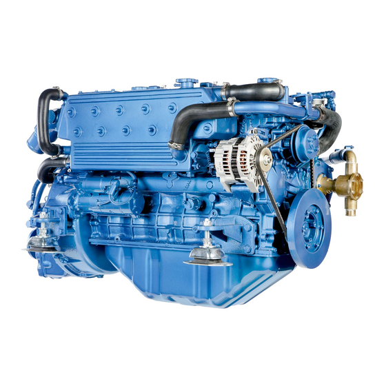
- Page 9 Injection pump: BOSCH type. Lubrication: forced-feed lubrication by trochoid pump. Electrical system: 12V (standard). 24V is optional. Alternator: 70A / 12V (MINI-74 – SM-105L) Starter Motor (12V): 2.2 kW (MINI-74) Alternator: 110A /12V (MINI-74 – SM-105L) Starter Motor (12V): 3.0 kW (SM-105L) 2.2 COOLING CIRCUIT...
- Page 10 2.2.2 “SEAWATER” COOLING CIRCUIT (Fig. 2.2) 0) Bottom cock 1) Intake connection with water filter 2) Water pump 3) Water / Water cooler 4) Wet exhaust elbow 5) Gear box cooler 2.3 LUBRICATION CIRCUIT Fig. 2.2 2.3.1 MOTOR 2.3.1 ENGINE Lubrication is forced with a lobe pumpand total filtration of the oil pumped tothe various lube points on the engine.The oil is forced by the pump through acontrol valve to the filter, the enginemain bearings and, by way of external pipelines, to the rocker arms.
- Page 11 (3) Fuel leak - off pipe (4 Injection pump Model Quantity (5) Priming puma. MINI-74 (6) Fuel filter. SM-105L (7) Tank. SM-103 (8) Fuel decanting filter (9) Fuel intake pipe. 2.4.1 INJECTION PUMP Injection pressure: 120 kg/cm (1707 psi / 11.77 MPa) 2.5 ELECTRICAL PLANT...
- Page 12 Check the electrical diagram (marine version) insert into the panel box. For Gen Set, check the technical information attached. It’s available only for 70A alternator. New electrical diagrams version in Technical Annexes ENG - 12 03917401.ENG rev. 2...
- Page 13 Check the electrical diagram (marine version) insert into the panel box. For Gen Set, check the technical information attached. It’s available only for 110 A alternator. Available in a MINI74 with serial no. > 166425 and for SM105 with serial no. > 59524 New electrical diagrams version in Technical Annexes ENG - 13 03917401.ENG rev.
- Page 14 WATERSEA TEMP. ALARM LAMP STARTER OIL PRESSURE MANOMETER TACHOMETRE HOUR COUNTER VOLTMETER ENGINE PART. NO. MINI-74 / SM-105L / SM-103 (12V) 60974130 MINI-74 / SM-105L / SM-103 (24V) 60975130 Standard Panel SVT 30 (12V / 24V) ENG - 14 03917401.ENG rev. 2...
- Page 15 2.6 TECHNICAL SPECIFICATIONS UNIDADES MINI-74 SM-105L SM-103 Cylinders number Bore Stroke Total desplacement c.c. 3331 4996 4996 Compression ratio 22:1 22:1 22:1 Min. Ilding speed r.p.m. Max engine speed r.p.m. 2500 2300 2500 Standard reducer gearbox TM-345A 1.5 : 1 &...
- Page 16 2.6.1 ENGINE DIMENSIONS MINI-74 + TM345A MINI-74 + TM93 MINI-74 + TM93A ENG - 16 03917401.ENG rev. 2...
- Page 17 SM-105L + TM93 SM-103 + TM93 SM-105L + TM93A SM-103 + TM93A ENG - 17 03917401.ENG rev. 2...
- Page 18 2.7 GEARBOX, GENERAL INFORMATION The hydraulic gearbox and the mechanically driven (SMI-R3) gearbox are made with high mechanical and seawater resistance grey cast iron alloy (for mechanically models) and aluminium, for the hydraulic models. Operation: With engine at idle speed, smoothly push forwardly the inverter lever (forward gear) and rear wardly (rear gear) according to the sense wanted.
- Page 19 3. TRANSPORT, HANDLING, STORAGE 3.0 GENERAL WARNINGS Refer to heading 1.3 for safety information. 3.1 PACKING AND UNPACKING The engine is shipped in various types of packing systems: STORAGE STACKING OF PACKS: Pallet with wooden crate (See heading covered area only. Max.
- Page 20 3.2.1 PACKING LIST (1) ASSEMBLED ENGINE (2) TECHNICAL DOCUMENTATION The technical documentation contains: instruction and user manual. Packing material must be disposed of in compilance with established law in the user’s country. Packing materials: Wood Steel nails Steel screws Plastic film Cardboard Metal or plastic straps 3.3 TRANSPORT AND HANDLING THE PACKED ENGINE When lifting and transporting the engine use EXCLUSIVELLY a fork lift or bridge crane of appropiate load capacity, with chains equipped with safety hooks suitable for lifting the load.
- Page 21 4. INSTALLATION 4.0 GENERAL WARNINGS Refer to heading 1.3 for safety information. 4.1 ASSEMBLY DATA TIGHTENING VALUES THREAD MINI–74 / SM-105L / SM-103 (kgf · m) (lbt · ft) Cylinder head bolts M12 x 1.75 12.0 87.0 Crankshaft pulley to crankshaft 50.0...
- Page 22 4.2 ENGINE SUPPLIES 4.2.1 CHANGING OIL 4.2.1.1 CHANGING ENGINE SUMP OIL Use oil that corresponds to the technical specifications in chapter 9. Oil shall be changed with a hot engine so as to be sure the oil is fully drained. This is done by removing the stopper and mounting the drain pump.
- Page 23 TM-93 / TM-93A TM-345 / TM-345A warning: the use of oil that does not conform to the technical specifications on chapter 9 will cause serious damage to the engine and invalidate the guarantee. when supplying the engine never ingest oil, fuel, coolant liquid, etc.. these substances are harmful to the personal health of the user if ingested 4.2.2 FILLING THE COOLING CIRCUIT As a refrigerating liquid, an anti-freeze of the brand KRAFFT ACU...
- Page 24 Run the engine for a few minutes until the cooling circuit is properly filled and free of air pockets. Check the coolant level and replenish if necessary. warning! after the first 50 hours of engine duty and at six months or 1000 hours intervals thereafter, addrust inhibiting agent AC88 to the coolant in the same proportions as indicate earlier.
-
Page 25: Instructions For First Starting
Connect control cable to the ball-joint fitted to the lever(A) and position the cable with the clamp (B). Adjust in a way that gas is not delivered until the inverter gear is engaged SM-105L SM-103 (f.b) Gearbox: Connect control cable to the lever by means of the ball- joint provided for this purpose and position cable with the clamp. -
Page 26: Bleeding Air From The Fuel Supply System Eng-26
(g) OTHER CHECKINGS (g.a) Carefully check the engine positioning points. (g.b) Check all screws are correctly tightened. (g.c) Check all water, oil and gas-oil pipe nipples, verifying if all them are well connected and correctly tightened. (g.d) Check exhaust and transmission systems. 5.1.1 BLEEDING AIR FROM THE FUEL SUPPLY SYSTEM On the first start-up of the engine, and if this has operated with the fuel tank empty, air may enter the feed system, and it is... -
Page 27: Load Running Test
5.2 PRELIMINARY RUNNING TESTS 5.2.1 NO-LOAD RUNNING TEST Run the engine at low speed for a few minutes. Keep a constant check on the oil pressure (see heading 2.3). 5.2.2 RUNNING-IN During initial run-in, may last lasts for the first 50 hours of duty, take into account the following points: (1) Daily checking performances must be made without failure. -
Page 28: Using The Engine Eng-28
6. USING THE ENGINE 6.0 GENERAL WARNINGS Refer to heading 1.3 for safety information. 6.1 STARTING THE ENGINE Place control lever at the neutral point. Rotate the ignition key to position “ON” Check oil pressure, battery charge lamps are lighted and the alarm is heard (refer to heading 2.5.1 for lamps position). -
Page 29: Stopping The Engine Eng-29
6.2 STOPPING THE ENGINE Allow to run at low speed for 4 or 5 minutes and place the gearbox remote control lever in the neutral position. Turn the starter key to “STOP” And maintain this position until the engine is fully stopped. With the engine stopped the starter key returns to “OFF”... -
Page 30: Long Inactivity Instructions
6.5 CONSERVATION warning! All engines not in use are subject to rusting and corrosion of machined surfaces that are not protected with a paint coating. The degree of corrosion depends on meteorological changes and climatic conditions. The following recommendations are therefore of a general nature but they will help prevent or reduce the risk of damage due torusting 6.6 LONG INACTIVITY INSTRUCTIONS When the engine is not to be used for a long period of time or during the winter time, certain operations must be carried out to keep it in perfect operationing condition. -
Page 31: Repair And Maintenance Eng-31
7. REPAIR AND MAINTENANCE 7.0 GENERAL WARNINGS Refer to heading 1.3 for safety information. 7.1 TYPE AND FREQUENCY OF INSPECTIONSAND MAINTENANCE INTERVENTIONS INCREASE THE FREQUENCY OF MAINTENANCE IN HARSH DUTYCONDITIONS. (FREQUENT STOPS AND STARTS, DUSTY SURROUNDINGS, PROLONGED WINTER SEASON, NO-LOAD RUNNING) IF POSSIBLE CHECK LEVELS ANDREPLENISH SUPPLIES WITH THEENGINE STOPPED AND ATAMBIENT TEMPERATURE WARNING! - Page 32 Service interval Inspection concept Daily 1ª 50 Every 200 Every 400 Every 800 Every 2 hour hour hour hour years Electrical system Every instrument Incandescent spark plug Alternator and starting motor Alternator belt and tension Battery level Exhaust Protections Airvent, … Cleaning Inspection, adjustment or filling Change...
- Page 33 EVERY 800 OPERATING HOURS EVERY 2 YEARS OPERATING HOURS Check the starting motor pinion and the flywheel toothed Change the refrigeration anti-freeze liquid. crown. Change alternator belt. Clean the fuel tank. Injector checking. Change the air filter element. Read heading 7.2.12 Lubricate with 0.7 ounce of grease the coolant pump Check the compression pressure of each cylinder.
- Page 34 Control and eventual adjustment of the alternator belt tension: Never adjust the belt tension with engine running. An excessive tension may cause a quick wear of the belt and alternator bearings. Otherwise, if the belt is excessively loose or has oil, and insufficient load due to the belt skidding can be caused.
- Page 35 Checking battery electrolite level and charge: Batteries require a very careful handling and frequent checkings. Proceed as shown below: (1) Always keep batteries dry and cleaned. (2) Regularly check terminal cleanliness. If dust is settled, terminals should be loosened, cleaned and smeared witha neutral grease layer.
- Page 36 (13) Check condition of sea water pump impeller and its eventual replacement: Driving impeller is neoprene and cannot rotate dried. If operated without water, the impeller can be broken. It is important therefore that a spare impeller is always available. To change the impeller, close water inlet cock, remove pump cover and with two screwdrivers prize it by removing the impeller from the shaft.
- Page 37 (18) Inspect injection pump: The fuel injection pump is one of the most relevant components of a diesel engine and therefore its handling requires the best care. In addition, the injection pump has carefully been adjusted at factory and should never be adjusted carelesly. Such adjustment, whenever is required, shall be made by a SOLÉ...
- Page 38 7.3 TROUBLE SHOOTINGS ENGINE FAILURE PROBABLES CAUSES FAILURE TO START C1 – C2 – C3 – C4 – C5 – C6 – C9 – E1 – E2 – E3 – E4 – E5 M3 – R1 – R3 – L4 STARTS THEN STOPS C1 –...
-
Page 39: Additional Instructions
8. ADDITIONAL INSTRUCTIONS 8.0 ADDITIONAL INSTRUCTIONS Refer to heading 1.3 for safety information 8.1 INSTRUCTIONS FOR DECOMMISSIONING, SCRAPPING AND DISPOSAL When you decide to decommission the engine, please contact SOLÉ S.A., we will provide you with the relevant instructions in relation to the laws in force at the time. - Page 40 AIR PROPERTIES - Output correction due to air properties. Specified outputs presuppose the following air properties (as per ISO 3046): Air pressure: 1000 mbar (750 mmHg) Air temperature: 25ºC Humidity: If the air deviates from these values, correction factors (in %) are found in the graphs below. Use the correction factors in “calculation of engine output”...
-
Page 41: Technical Annexes Eng-41
9. TECHNICAL ANNEXES 9.0 OIL SPECIFICATIONS 9.0.1 ENGINE OIL TO BE USED Use Sole Diesel SAE 15W40 oil. Its service classification is as follows: as follows: OIL VISCOSITY: Select oil viscosity most suitable for the atmospheric temperatures on which the API CE/CF-4/SG engine should be operated. - Page 42 When the engine is fitted inclined, the oil dipstick must be modified to avoid problems of aspiration by the oil pump. See the table enclosed for modification level in rod oil. Increase level D, starting off of level H of the original oil dipstick. ENGINE INCLINATION (MINI-74) (SM-105L) (SM-103) 4º 12.5 mm...
- Page 44 MARINE DIESEL ENGINES MARINE GEN SET SOLÉ S.A. Oficina Técnica Ctra. Martorell a Gelida (C-243b), km. 2 08760 Martorell Barcelona - Spain Tel. (+34) 93 775 14 00 Fax. (+34) 93 775 30 13 e-mail: sole@solediesel.com www.solediesel.com Ref. 03917401.ENG Ed. 3 rev. 2...
Need help?
Do you have a question about the SM-105L and is the answer not in the manual?
Questions and answers