Table of Contents
Advertisement
Quick Links
Advertisement
Table of Contents

Related Manuals for Sole Diesel MINI-62


Summary of Contents for Sole Diesel MINI-62
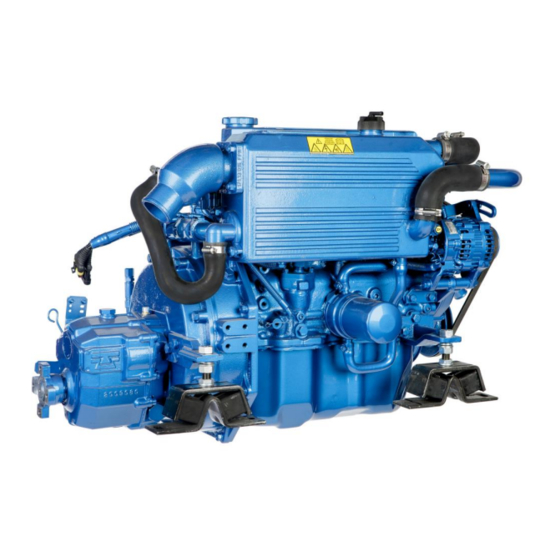
- Page 1 ENGINE INSTRUCTIONS MANUAL MINI 62G...
-
Page 3: General Warings
CONTENTS 0. INTRODUCTION ENG-1 0.0 FOREWORD 0.1 USING THE INSTRUCTION MANUAL 0.1.1 IMPORTANCE OF THE MANUAL 0.1.2 CONSERVING THE MANUAL 0.1.3 CONSULTING THE MANUAL 0.1.4 SYMBOLS IN THE MANUAL ENG-2 1. GENRAL INFORMATION ENG-3 1.1 ENGINE MANUFACTURER’S INDENTIFICATION DATA 1.2 INFORMATION REGARDING TECHNICAL ASSISTANCE / MAINTENANCE OF THE ENGINE 1.3 GENRAL SAFETY NOTICIES 1.3.1 INFORMATION REGARDING RESIDUAL RISKS ENG-4... -
Page 4: Table Of Contents
CONTENTS 5. PREPARING THE ENGINE FOR USE ENG-19 5.0 GENERAL WARINGS 5.1 INSTRUCTIONS FOR FIRST STARTING 5.1.1 BLEEDING AIR FROM THE FUEL SUPPLY SYSTEM ENG-20 5.2 PRELIMINARY RUNNING TEST 5.2.1 NO-LOAD RUNNING TEST 5.2.2 RUNNING – IN 6. USING THE ENGINE ENG-21 6.0 GENERAL WARINGS 6.1 STARTING THE ENGINE... - Page 5 0. INTRODUCTION 0.0 FOREWORD Dear client: The SOLÉ S.A. engine you have purchased is a product of the highest technological quality Our Service SOLÉ DIESEL department has recently been strengthened to ensure even better service for all our clients. Reliable duty and long life of the engine you have purchased can only be guaranteed if exclusively original spare parts are used, and ensure that the unit is serviced by our specialized personnel.
- Page 6 0.1.4 SYMBOLS IN THE MANUAL The Safety symbols and notices shown below are used throughout this publication to draw the user’s attention to situations or hazardous procedures that could damage the engine or cause personal injury, and to indicate suitable practices to assure the correct operation of the engine.
- Page 7 1. GENERAL INFORMATION 1.1 ENGINE MANUFACTURER’S IDENTIFICATION DATA MANUFACTURER: SOLÉ, S.A. Ctra. de Martorell a Gelida, km 2 08760 MARTORELL (BARCELONA) SPAIN MODEL: _____________________________ TRADE DESIGNATION: Fig. 1.1 MINI-62G ______________________________ The above data can be quickly identified in the Fig. 1.2 following position: - Engine nameplate showing identification data (see Fig.
- Page 8 Before starting work the operator must be aware of the position and operation of all commands and the characteristics of the engine; make a daily check of the safety devices on the engine. Disabling or tampering with the safety devices on the engine is strictly prohibited.
- Page 9 4.2.2 of this manual 1) Water pump 2) Water cooler 3) Thermostat 4) Bypass pipe 5) Boiler connections (Optional) Thermostat valve operating values: MINI-62 / 62L / 62G Start opening +76.5 ºC End opening +90 ºC CIRCUIT CAPACITY (LIT.) MINI-62G 9.50...
- Page 10 2.2.2 “SEAWATER” COOLING CIRCUIT (Fig. 2.2) 0) Bottom cock 1) Intake connection with water filter 2) Water pump 3) Water / Water cooler 4) Wet exhaust elbow 5) Gear box cooler (ONLY SMI-R2 y SMI-R3 GEARBOX) Fig. 2.2 2.3 LUBRICATION CIRCUIT 2.3.1 ENGINE Lubrication is forced with a lobe pumpand total filtration of the oil pumped tothe various lube points on the engine.The oil is forced by the pump through acontrol valve to the filter, the enginemain bearings and, by way of external pipelines, to the rocker arms.
- Page 11 2.4 FUEL CIRCUIT (1) Fuel injection Model Quantity MINI – 62G (2) Fuel injection pipe (3) Fuel leak - off pipe (4) Injection pump (5) Priming pump. (6) Fuel filter (7) Tank Fig. 2.4 2.4.1 INJECTION PUMP Circuit pressure: 0.3 / 0.4 bar Injection pressure: = 120 ±...
- Page 12 Check the electrical diagram insert into the panel box ENG - 8 03917101.ENG rev. 3...
- Page 13 2.5.2. ELECTRICAL PLANT AND INSTRUMENTAL PANEL SVT DESCRIPTION GLOW PLUG OPERATION LAMP BATTERY CHARGE LAMP WATER TEMPERATURE ALARM LAMP OIL PRESSURE ALARM SEAWATER TEMPERATURE ALARM LAMP THACHOMETER HOUR COUNTER COOLANT TEMPERATURE GAUGE STARTER ENGINE Part. No. MINI-62G (12V) 60971135 Standard panel SVT 20 (12V) ENG - 9 03917101.ENG rev.
- Page 14 HURTH 150V (1) Engines introduced on the market before January 18, 2017 have a power of 43.4 kW / 58.2 hp for the mini-62 and 38.20 kW / 51.20 hp for the mini-62L. (2) Read section 9.0.2 (inverters type SMI-R2 and SMI-R3), to know what ATF oil they use.
- Page 15 2.6.1 ENGINE DIMENSIONS GEARBOX TYPE SMI-R2 GEARBOX TYPE TM-345A ENG - 11 03917101.ENG rev. 3...
- Page 16 GEARBOX TYPE SMI-R3 GEARBOX TYPE TM-93 2.7 REDUCER GEARBOX The mechanically driven (SMI-R2 and SMI-R3) gearbox is made with high mechanical and seawater resistance grey cast iron alloy. Operation: With engine at idle speed, smoothly push forwardly the inverter lever (forward gear) and rearwardly (rear gear) according to the sense wanted.
- Page 17 3. TRANSPORT, HANDLING, STORAGE 3.0 GENERAL WARNINGS Refer to heading 1.3 for safety information. 3.1 PACKING AND UNPACKING The engine is shipped in various types of packing systems: STORAGE STACKING OF PACKS: Pallet with wooden crate covered area only Máx. 1+1 (See heading 3.1.1) Pallet with skeleton crate covered area only...
- Page 18 countersing the note and advise SOLE S.A., preferably by telefax. 3.2.1 PACKING LIST (1) ASSEMBLED ENGINE (2) TECHNICAL DOCUMENTATION The technical documentation contains: instruction and user manual. Packing material must be disposed of in compilance with established law in the user’s country. Packing materials: Wood Steel nails Steel screws Plastic film Cardboard Metal or plastic straps 3.3 TRANSPORT AND HANDLING THE PACKED ENGINE When lifting and transporting the engine use EXCLUSIVELLY a fork lift or bridge crane of appropiate load capacity, with chains...
- Page 19 4. INSTALLATION 4.0 GENERAL WARNINGS Refer to heading 1.3 for safety information 4.1. ASSEMBLY DATA PARES DE APRIETE TYPE MINI – 62G THREAD (kgf · m) (lbt · ft) Cylinder head bolts 12.0 87.0 Crankshaft pulley to crankshaft 40.0 Main bearing bolts 61.0 Tuercas ciegas biela 40.0...
- Page 20 4.2 ENGINE SUPPLIES 4.2.1 CHANGING OIL 4.2.1.1 CHANGING ENGINE SUMP OIL Use oil that corresponds to the technical specifications in chapter 9. Oil shall be changed with a hot engine so as to be sure the oil is fully drained. This is done by removing the stopper and mounting the drain pump.
- Page 21 Warning: The use of oil that does not conform to the technical specifications on chapter 9 will cause serious damage to the engine and invalidate the guarantee. When supplying the engine never ingest oil, fuel, coolant liquid, etc. These substances are harmful to the personal health of the user if ingested 4.2.2 FILLING THE COOLING CIRCUIT As a refrigerating liquid, an anti-freeze of the brand KRAFFT ACU...
- Page 22 4.2.3 REFUELING Always use clean, filtered gas oil. Never use either kerosene or heavy oils. On topping up with fuel, use a funnel with a metallic mesh filter, to keep out impurities or foreign bodies which may cause problems in the fuel injection circuit. Whenever possible, keep the fuel tank full, as temperature changes may cause condensation of the damp air present in the tank so that water accumulates at the bottom, giving rise to corrosion or making it impossible to start the engine if this is aspirated by the fuel pump.
-
Page 23: Instructions For First Starting
5. PREPARING THE ENGINE FOR USE 5.0 GENERAL WARNINGS Refer to heading 1.3 for safety information. 5.1 INSTRUCTIONS FOR FIRST STARTING Do not alter the functioning conditions of the engine by changing the settings of factory sealed parts. Tampering with such parts automatically invalidates the guarantee. -
Page 24: Bleeding Air From The Fuel Supply System Eng-20
(g) OTHER CHECKINGS (g.a) Carefully check the engine positioning points. (g.b) Check all screws are correctly tightened. (g.c) Check all water, oil and gas-oil pipe nipples, verifying if all them are well connected and correctly tightened. (g.d) Check exhaust and transmission systems. 5.1.1 BLEEDING AIR FROM THE FUEL SUPPLY SYSTEM On the first start-up of the engine, and if this has operated with the fuel tank empty, air may enter the feed system, and it is... -
Page 25: Using The Engine Eng-21
6. USING THE ENGINE 6.0 GENERAL WARNINGS Refer to heading 1.3 for safety information. 6.1 STARTING THE ENGINE For all engines Place control lever at the neutral point. Rotate the ignition key to position “ON” Check oil pressure, battery charge lamps are lighted and the alarm is heard (refer to heading 2.5.1 for lamps position). -
Page 26: Stopping The Engine Eng-22
6.2 STOPPING THE ENGINE Allow to run at low speed for 4 or 5 minutes and place the remote control lever in the neutral position. Rotate the ignition key to the “OFF” position. If engine is not to run for a longer period, it is advisable to shut fuel and water cocks and also to disconnect the battery. -
Page 27: Long Inactivity Instructions
6.5 CONSERVATION Warning! All engines not in use are subject to rusting and corrosion of machined surfaces that are not protected with a paint coating. The degree of corrosion depends on meteorological changes and climatic conditions. The following recommendations are therefore of a general nature but they will help prevent or reduce the risk of damage due to rusting 6.6 LONG INACTIVITY INSTRUCTIONS When the engine is not to be used for a long period of time or during the winter time, certain operations must be carried out to... -
Page 28: Repair And Maintenance Eng-24
7. REPAIR AND MAINTENANCE 7.0 GENERAL WARNINGS Refer to heading 1.3 for safety information. 7.1 TYPE AND FREQUENCY OF INSPECTIONSAND MAINTENANCE INTERVENTIONS INCREASE THE FREQUENCY OFMAINTENANCE IN HARSH DUTY CONDITIONS. (FREQUENT STOPS AND STARTS, DUSTY SURROUNDINGS, PROLONGED WINTER SEASON, NO-LOAD RUNNING) IF POSSIBLE CHECK LEVELS ANDREPLENISH SUPPLIES WITH THE ENGINE STOPPED AND AT AMBIENT TEMPERATURE WARNING! - Page 29 Service interva Inspection concept Daily 1ª 50 200 hour 400 hour 800 hour Every 2 hour years Electrical system Every instrument Incandescent spark plug Alternator and starting motor Alternator belt and tension Battery level Exhaust Protections Airvent, … Cleaning Inspection, adjustment filling Change...
- Page 30 7.2 OPERATING DESCRIPTION Change engine and gearbox oil: See heading 4.2.1. Change oil filter (Fig. 7.1): The oil filter is located under the air filter. Change the oil filter after the firsts 50 operating hours and afterwards every 200 hours. The oil filter being a cartridge type of easy handling shall not be cleaned.
- Page 31 Water filter cleaning: It is important to fit between the engine and the bottom cock a filter to avoid that any imputities existing in these a water might clog the cooling conducts. Filter shall be cleaned every 200 hours by loosening the wing nut and removing the filtering component.
- Page 32 Replace the fuel filter element (engine): The fuel filter is cladded and cannot be cleaned. It must be replaced at least once every 12 months. To perform the filter change: Shut off the cock located at the tank delivery. Unscrew cover filter with a chain spanner. Screw the new filter to the cover with the hand and at the same time replace the rubber seals.
- Page 33 (14) Check alternator and starting motor: The engine has a standard alternator of 12V 50 Amps, with an electric regulator incorporated and an output for the revolutions counter. Regularly check the electrical connections, its relevant positioning and the good terminal contact. For the starting motor, check brush wear and switch sour face roughness.
- Page 34 7.3 TROUBLE SHOOTINGS ENGINE FAILURE PROBABLES CAUSES FAILURE TO START C1 – C2 – C3 – C4 – C5 – C6 – C9 – E1 – E2 – E3 – E4 – E5 M3 – R1 – R3 – L4 STARTS THEN STOPS C1 –...
-
Page 35: Additional Instructions
8. ADDITIONAL INSTRUCTIONS 8.0 ADDITIONAL INSTRUCTIONS Refer to heading 1.3 for safety information 8.1 INSTRUCTIONS FOR DECOMMISSIONING, SCRAPPING AND DISPOSAL When you decide to decommission the engine, please contact SOLÉ S.A., we will provide you with the relevant instructions in relation to the laws in force at the time. - Page 36 AIR PROPERTIES - Output correction due to air properties. Specified outputs presuppose the following air properties (as per ISO 3046): Air pressure: 1000 mbar (750 mmHg) Air temperature: 25ºC Humidity: If the air deviates from these values, correction factors (in %) are found in the graphs below. Use the correction factors in “calculation of engine output”...
-
Page 37: Solé Diesel Limited Warranty
9. SOLÉ DIESEL WARRANTY Read the manual and documents delivered with each engine before carrying out any of the operations or presenting any queries. The engine is supplied without any liquids. Ensure that the liquids used match the specifications contained in Solé Diesel manuals. The application of the conditions described in this document shall only be effective for engines or generator sets that have been invoiced after January 1, 2012. -
Page 38: After-Sales Service Contact
from another manufacturer are inappropriate for use alongside Solé Diesel products or are the cause of the failure or poor operation of our products. The warranty shall not apply if the revisions and maintenance services indicated in the User and Maintenance Manuals have not been adhered to properly. -
Page 39: Service Assistance Eng-35
The following information must also be provided by the purchaser: a) Owner’s name, address and contact telephone number. b) Product model and serial number. c) Number of service hours of the product. d) Detailed description of the problem. e) Information regarding any repair or installation performed by a service not included in the Solé Diesel distribution network, as well as the services performed. -
Page 40: Oil Specifications
10.0.2 GEARBOX OIL For mechanical geared SMI-R2 and SMI-R3 gearboxes, it is recommended to use the same type of oil that is used in the engine, a Sole Diesel SAE 15W/ 40, excepting the following models indicated in the table below. Attention! Different gearboxes of type SMI-R2 and SMI-R3 exist, in which it is necessary to use oil type ATF. -
Page 41: Fuel Injection Timimg
5.5 l 6.5 l 10.3 FUEL INJECTION TIMING (BTDC) The BTDC are diferent depending the serial number engine. Please, contact to SOLE. ENGINE, PART no. BTDC MINI-62 G 20º 171.20.000 (serial no. < 26906) 6º 171.20.000.1 (serial no. > 26906) 8º... - Page 42 11. INSPECTION PRIOR TO THE DELIVERY OF PROPULSION ENGINES ENG - 38 03917101.ENG rev. 3...
- Page 43 ENG - 39 03917101.ENG rev. 3...
- Page 44 12. MAINTENANCE LOG DATE HOURS DESCRIPTION SERVICE NAME ENG - 40 03917101.ENG rev. 3...
- Page 45 Version June 2016 SOLÉ, S.A. CIF ES‐A08191223 www.solediesel.com C‐243b, km. 2, P.O. BOX 15 08760 ‐ Martorell (Barcelona) SPAIN Marine engines ‐ Gensets ‐ Accesories Declaration of Conformity for Recreational Craft Propulsion Engines (inboard engines and stern drive engines without integral exhaust) with the requirements of Directive 2013/53/EU Name of engine manufacturer: SOLÉ, S.A. Address: Ctra. C‐243b, Km. 2 Town: Martorell Post Code: 08760 Country: Spain Name of Authorised Representative: Address: Town: Post Code: Country: Name of Notified Body for exhaust emission assessment: EUROCONTROL Address: Santa Engracia, 56 Town: Madrid Post Code: 28010 Country: Spain ID Number: 0057 Conformity assessment module used for B+C/C1 exhaust emissions: or engine type‐approved according to: Directive 97/68/EC EC Regulation No 595/2009...
- Page 46 SOLÉ, S.A. CIF ES‐A08191223 www.solediesel.com C‐243b, km. 2, P.O. BOX 15 08760 ‐ Martorell (Barcelona) SPAIN Marine engines ‐ Gensets ‐ Accesories Essential requirements Specify the harmonised 2 standards reference to relevant articles in or other reference documents used Annex IB & IC of the Directive) (with year of publication like “EN ISO 8666:2002”) Tick only one box per line All lines right of ticked boxes must be filled in Annex I.A ‐ Design and Construction of Products Design and Construction of Products (Annex I A.) Chapter 1.1 (Owner's Manual) Annex I.B – Exhaust Emissions Propulsion Engine Identification (Annex I B.1) Chapter 1 Exhaust Emission Requirements (Annex I B. 2) EN ISO 8178‐1:1996 Chapter 7.1 (Owner's Manual) Durability (Annex I B.3) Owner’s manual (Annex I B.4) See Declaration of Conformity of the recreational craft in which the engine(s) Annex I.C – Noise Emissions has (have) been installed 1. Annex I.C – Noise Emissions 2.Standards published in EU Official Journal...
- Page 48 MARINE DIESEL ENGINES SOLÉ S.A. Dpto. Publicaciones Técnicas Ctra. Martorell a Gelida km. 2 08760 Martorell Barcelona - Spain Tel. (+34) 93 775 14 00 Fax. (+34) 93 775 30 13 e-mail: sole@solediesel.com www.solediesel.com Ref. 03917101.ENG Ed. 2 rev. 1...
Need help?
Do you have a question about the MINI-62 and is the answer not in the manual?
Questions and answers