Raymarine ST70+ Operating Manual
Hide thumbs
Also See for ST70+:
- Installation manual (73 pages) ,
- User reference manual (60 pages) ,
- User's reference manual (48 pages)
Table of Contents
Advertisement
Quick Links
Advertisement
Table of Contents
Troubleshooting

Related Manuals for Raymarine ST70+


Summary of Contents for Raymarine ST70+
- Page 1 ST70+ User Reference Manual Document reference: 85024-1 Date: January 2009...
- Page 2 Autohelm, HSB, RayTech Navigator, Sail Pilot, SeaTalk and Sportpilot are UK registered trademarks of Raymarine UK Limited. Pathfinder and Raymarine are UK registered trademarks of Raymarine Holdings Limited. 45STV, 60STV, AST, Autoadapt, Auto GST, AutoSeastate, AutoTrim, Bidata, G Series, HDFI, LifeTag, Marine Intelligence, Maxiview, On Board,Raychart, Raynav, Raypilot, RayTalk, Raystar, ST40, ST60+, Seaclutter, Smart Route, Tridata, UniControl and Waypoint Navigation are trademarks of Raymarine UK Limited.
-
Page 3: Table Of Contents
Contents Preface ........................v Safety notices ....................v EMC conformance ................... v Pressure washing .................... v Certified installation ..................vi Product documents ..................vi Technical accuracy ................vi Product disposal ..................... vi Chapter 1:General information ..............1 1.1 Introduction ................... 1 1.2 Product basics ..................1 Concept.................... - Page 4 ST70+ User Reference Manual Date & Time..................17 Setting date format ................17 Setting time format................18 Setting local time ................18 Leaving date & time setup ..............18 Data units .................... 19 Changing units .................. 19 Leaving units setup................20 Initial setup end routine................
- Page 5 Speed calibration for conventional speed transducer....... 41 Starting speed calibration ..............41 Set to SOG ..................42 Manual speed calibration ..............42 Speed calibration for smart transducer..........43 Add point .................... 44 Delete point ..................44 Return to normal operation ..............44 2.5 Checking autopilot operation ..............
- Page 6 ST70+ User Reference Manual Chapter 4:Maintenance & Troubleshooting ..........59 4.1 Introduction ..................59 Servicing & safety................59 EMC ....................59 4.2 Maintenance ..................59 Cleaning ....................60 Cabling ....................60 4.3 Troubleshooting .................. 60 First considerations ................60 Procedures..................60 Using the display self-monitoring features ...........
-
Page 7: Preface
Pressure washing Do NOT pressure wash any Raymarine product. Subjecting any Raymarine product to high pressure washing may cause subsequent water intrusion and failure of the product. Raymarine will not warranty product subjected to high pressure washing. -
Page 8: Certified Installation
Certified installation Raymarine recommends certified installation by a Raymarine approved installer. A certified installation qualifies for enhanced warranty benefits. Contact your Raymarine dealer for further details and refer to the separate warranty document packed with your product. Product documents The following user documents are available for ST70+: •... -
Page 9: Chapter 1:General Information
Chapter 1: General information 1.1 Introduction This manual provides commissioning and other setup information for ST70+ displays and associated keypad controllers. It is also intended for users who want to more fully understand the concepts of ST70+ and want to get the most out of their product. For day-to-day use of ST70+, refer to the ST70+ Operating Guide. -
Page 10: Sail Boat Pilot Controller Keypad
ST70+ User Reference Manual Other buttons and their functions depend on the keypad type. Sail boat Pilot Controller keypad Sail boat Pilot Controller keypad buttons and functions are: MENU • button. Selects the Main Menu which gives access • Wind Vane mode. •... -
Page 11: Instrument Keypad
Chapter 1: General information Instrument keypad Instrument keypad buttons and functions are: MENU • button. Selects the Main Menu which provides access to: • Setup and reset functions. • Self test routines and diagnostic information. PAGE UP PAGE DN • &... -
Page 12: Maximum, Minimum & Average Indicators
ST70+ User Reference Manual Maximum, minimum & average indicators Maximum, minimum & average value indicators are displayed on speed, wind speed and wind angle screens, as in the following illustration: Average value indicator Minimum value indicator Maximum value indicator Commonly used control functions Many ST70+ setup functions and values, plus many display options are selected by scrolling to the required function or value, then confirming the value. -
Page 13: Setup Principles
Chapter 1: General information 1.3 Setup principles A newly-installed ST70+ system must be commissioned as described in Chapter 2:, Commissioning Procedures, before being used for operational purposes. First use after installation The first part of the commissioning procedure is initial setup (summarized in Figure 1-1). -
Page 14: Display Types & Grouping
ST70+ User Reference Manual The initial setup procedure enables you to: • Select system language. • Select vessel type. • Set up display types & groups (see Figure 1-2 ) • Set time and date formats. • Set local time value. •... -
Page 15: Normal Operation
Instrument keypads, respectively. There two types of Pilot Controller keypad, one for sail boat installations, another for power boats. Pilot Controllers ST70+ Pilot Controllers are used to control Raymarine autopilots. A summary of generic ST70+ Pilot Controller day-to-day functions is shown in Figure 1-3 . Sail boat functions In addition to the generic Pilot Controller functions in Figure 1-3 , Pilot Controllers on sail boats also have access to Wind Vane and AutoTack modes of autopilot operation. -
Page 16: User Setup
ST70+ User Reference Manual Hold down POWER ON Normal Operation Keypad functions Select next Pilot Controller in group The pilot view at switch Press & release on, is same as when Select Standby mode STANDBY Pilot Controller last (you have manual control) switched off Select Auto mode AUTO... -
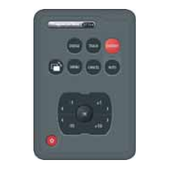
Page 17: Power Boat Functions
Chapter 1: General information Power boat functions In addition to the generic Pilot Controller functions (Figure 1-3 ), Pilot Controllers on power boats also have access to fishing patterns, via the Pilot Controller Main menu. Fishing patterns Fishing patterns enable you to automatically navigate over a preset course in Auto mode. - Page 18 ST70+ User Reference Manual Hold down POWER ON Normal Operation Instrument keypad Select previous The operating page at PAGE UP switch on, is same as operational page when intrument last Select next Instrument switched off Select next PAGE DN in group operational page Press &...
-
Page 19: System Information
Chapter 1: General information 1.5 System information ST70+ displays and keypads connect to Raymarine SeaTalk systems. Further information on SeaTalk is given in the SeaTalk Reference Manual. When connected to a SeaTalk system, the ST70+ displays repeat the data on the bus. -
Page 20: Commissioning Requirement
The detailed requirement for autopilot calibration depends on the autopilot type. The procedures given in this manual are those for a ‘typical’ Raymarine autopilot system. If necessary adapt the procedures in this manual to suit your system. If you need... -
Page 21: Chapter 2:Commissioning Procedures
Autopilot calibration The detailed requirement for autopilot calibration is determined by the autopilot. The autopilot calibration procedures in this chapter are those for a ‘typical’ Raymarine autopilot system. If necessary adapt these procedures to suit your system. If you need assistance, please contact your Raymarine dealer. -
Page 22: Switch On
ST70+ User Reference Manual Switch on Language At an ST70+ keypad, press the power button to switch on the displays. When an ST70+ system is first switched on after installation, one display shows a select Language menu. This is the active English (UK) display Other displays show a Select Display icon... -
Page 23: Setting Vessel Type
Chapter 2: Commissioning Procedures Setting Vessel Type Vessel Type The Vessel Type menu enables you to automatically apply the optimum system settings for your vessel type. The options are: • Race Sail • Inboard Speed Boat Inboard Speedboat • Sail Cruiser •... - Page 24 ST70+ User Reference Manual 3. Press to display the Display type setup Display type page. 4. Scroll to select either Instrument or Autopilot, Autopilot as required. Note: From this point, you must use a keypad type appropriate to the display type you have selected. Configure this display as an instrument or autopilot controller Press OK to accept...
-
Page 25: Date & Time
Chapter 2: Commissioning Procedures 13. When all displays are set as you want, and with the Configure this display page MENU displayed, press , to leave the Setting display types and groups procedure, and display either: • A Time & date summary page, if your system provides GPS information, •... -
Page 26: Setting Time Format
Time & Date setup menu. Setting local time Note: If your ST70+ display is connected to a Raymarine multi- Use < & > to adjust. CANCEL exits without saving. function display, then the time offset is controlled by the... -
Page 27: Data Units
Chapter 2: Commissioning Procedures Data units The Units summary comprises two pages and Units summary shows units currently in use. You can accept all or 6 pt Speed change any of the data unit settings. You can set:. Distance Depth •... -
Page 28: Leaving Units Setup
Setting rudder hard over time. The exact procedures are dependent on the type of autopilot. Typical procedures are given here, but you may need to adapt these procedures to suit your installation. If you require advice or assistance, please contact your local Raymarine dealer. -
Page 29: Dockside Wizard
Rotary Drive Type 2 Verado Note: If your drive type is not included, seek advice from your Raymarine dealer. 2. Press OK to save your setting and display the next setup page. This is either: • The Rudder check (center) page, if the boat has a rudder reference transducer, •... -
Page 30: Rudder And Motor Checks For Systems With A Rudder Reference Transducer
ST70+ User Reference Manual Rudder and motor checks for systems with a Rudder Reference transducer After setting the drive type, the Rudder check page Rudder Check (center) is displayed, if your system has a Rudder Reference transducer. If this is the case, carry out the rudder and motor checks as follows: 1. -
Page 31: Rudder And Motor Checks For Systems Without A Rudder Reference Transducer
Chapter 2: Commissioning Procedures 8. Press , to display the Motor Check entry Motor Check page. IS IT SAFE TO TAKE THE HELM! Press CANCEL to exit Press OK to continue 9. Press to display a Motor Check caution Motor Phasing Non-referenced page. - Page 32 ST70+ User Reference Manual Carry out the rudder and motor checks as follows: 1. Press to display a Motor Check caution Motor Phasing Non-referenced page. Please center and let go of 2. If it is safe to proceed. press , then check rudder and release any rudder drive clutch.
-
Page 33: Hard Over Time
Chapter 2: Commissioning Procedures Hard over time Note: Not applicable to boats with a rudder reference transducer. On boats without a rudder reference transducer, it is of critical importance to set the hard over time, to ensure accurate autopilot operation. To do this: At a convenient Pilot Controller: MENU 1. -
Page 34: Depth Offsets
ST70+ User Reference Manual A Wind transducer may also be fitted, to provide wind speed and direction information. Depth offset and sea temperature must be calibrated as part of the Dockside setup, but the exact method for calibrating these parameters depends on which transducers are fitted: •... - Page 35 • The correct Depth Offset, using the proce- dure described under either Calibrating Depth conventional transducers or Calibrating smart transducers as appropriate Raymarine Serial no.135260 • The correct Water Temperature using the Press OK to select procedure described under either Calibrating conventional transducers or Calibrating smart transducers as appropriate.
-
Page 36: Calibrating Conventional Transducers
Depth Offset option, then press Depth Offset to display the Depth Offset setup page. • Check the type and value of the offset Raymarine Serial no. 211342 currently applied: Press OK to select • If the offset type is what you require and the... -
Page 37: Setting Water Temperature
Speed transducer setup menu. 3. Scroll to the Temperature Offset option. Speed 4. Press to display the Temperature Offset Raymarine setup page. Serial no.165321 Press OK to select 5. Using a suitable thermometer, measure the Temperature Offset water temperature, then scroll to set the correct system temperature value. -
Page 38: Calibrating Trim Tabs
ST70+ User Reference Manual PAGE UP 4. If necessary, press to select the upper Depth Offset (offset type) adjust box. Keel 5. Scroll to either Water line, Keel or Transducer, as required. If you select Transducer, an offset value of zero is automatically applied. 6. -
Page 39: Setting Magnetic Variation
Chapter 2: Commissioning Procedures 2. Scroll to Advanced Options then press OK to Advanced Options select the Advanced Options menu 3. Scroll to select the Ground Wind option. Ground Wind Press OK to select 4. Press to display the Ground Wind setup Ground Wind box. -
Page 40: Changing Display Response Rate
ST70+ User Reference Manual 5. If you selected the OFF or SLAVE mode, proceed from step 6. If you selected the ON mode: PAGE DN Press to select the lower (value) box. ii. Scroll to set the correct variation value. 6. -
Page 41: Rudder Limit
Chapter 2: Commissioning Procedures Rudder limit The rudder limit adjust function is available only if the rudder reference option is fitted. It enables you to adjust the rudder so it will not put a strain on the end stops. To do this: MENU 1. -
Page 42: Open Water Calibration
ST70+ User Reference Manual 2.4 Open water calibration WARNING: Ensure you have sufficient open space for calibration The open water calibration manoeuvres require a clear, familiar area of water, with enough depth for your vessel. Ensure you are not likely to collide with any vessel or other obstruction during calibration. -
Page 43: Starting Open Water Calibration
Chapter 2: Commissioning Procedures Starting open water calibration If the SeaTrial calibration page is not displayed, Sea Trial calibration used the following procedure to gain access: Before you can use your autopilot you need to do 1. Use the Select Display button on an appropri- some open water checks. -
Page 44: Aligning The Compass To Gps
ST70+ User Reference Manual iii. Repeat the calibration process. If deviation remains at more than 5 degrees, contact your Raymarine dealer for advice. If the deviation figure exceeds 15° or the display shows no deviation value, the compass is being affected by ferrous objects on your boat. Move the compass to a better location. -
Page 45: Autolearn
Chapter 2: Commissioning Procedures AutoLearn AutoLearn enables the autopilot to ‘learn’ the vessel’s steering characteristics, by carrying out a number of maneuvers. WARNING: Clear water When using Autolearn you must have significant clear water both in front and to the sides of the vessel. This is needed to accommodate a series of maneuvers, which include sudden, sharp turns. -
Page 46: Next Actions
ST70+ User Reference Manual 4. When AutoLearn is complete and a PASS mes- AutoLearn sage is displayed, then AutoLearn is complete. Press to leave calibration and return to nor- PASS mal operation with the autopilot in Standby mode, i.e. with manual helm. If FAIL is displayed, press to repeat the YOU HAVE THE HELM. -
Page 47: Wind Transducer Setup
A Wind transducer, carry out the Wind transducer setup procedure below. Depth • A Speed transducer, carry out the Speed Raymarine calibration on page 40. Serial no.135260 Wind transducer setup Press OK to select The wind transducer setup procedures are used to: •... -
Page 48: Alignment
ST70+ User Reference Manual Alignment To carry out the wind vane alignment: Align Vane 1. With the Wind transducer setup menu displayed, scroll to Align Vane, then press 26° display the Align Vane screen 2. Sail the boat directly into the wind, then press to accept the alignment and return to the Now align the wind vane. -
Page 49: Speed Calibration For Conventional Speed Transducer
1. With the Transducers Found menu displayed (see Preliminary procedure on page 38), use the appropriate Instrument keypad to scroll to the Speed option. Speed Raymarine Serial no.19863 Press OK to select 2. Press to select the Speed transducer setup Speed menu. -
Page 50: Set To Sog
ST70+ User Reference Manual Set to SOG To use SOG to set the correct speed: 1. Carry out the Starting speed calibration procedure (above). PAGE DN 2. Press to highlight the calibration factor field. 3. In conditions of zero tide and zero Calibration speed current, run your vessel at Calibration... -
Page 51: Speed Calibration For Smart Transducer
DST Details page, then press , to display the Depth Offset setup page. 3. Ensure the correct depth offset is correct, then Raymarine Serial no.175417 press to display the DST Temperature page. Press OK to select 4. Press... -
Page 52: Add Point
ST70+ User Reference Manual Add point To add a new speed calibration value: 1. At the Airmar Speed Calibration menu, scroll to Add Point Add point then press to display the Add Point page. 24 kts 2. Set your boat speed through the water so that the displayed SOG value is the speed you want as a calibration speed. -
Page 53: Checking Rudder Gain
Chapter 2: Commissioning Procedures Checking rudder gain To determine whether the rudder gain is set correctly, carry out the following test: 1. Ensure you have set the autopilot response to level 5, as described above. 2. Motor your boat at a typical cruising speed in clear water. It is easier to recognize the steering response in calm sea conditions where wave action does not mask steering performance. -
Page 54: Rudder Damping
ST70+ User Reference Manual Rudder damping If the autopilot is ‘hunting’, i.e. continuously moving the steering backwards and forwards by small amounts, use the Setting rudder damping procedure in Chapter 3:Setup Information to improve autopilot stability. Setting AutoTrim AutoTrim determines how quickly the autopilot applies ‘standing helm’ to correct for trim changes, caused, for example, by changes in the wind load on the superstructure, or an imbalance of engines. -
Page 55: Chapter 3:Setup Information
Setting alarms Changing language Any change to the language is applied across the entire ST70+ system. To change the language used on your ST70+system: 1. At a convenient ST70+ keypad use the Select Display button to select a conve- MENU nient display, then press to display the Main menu. -
Page 56: Changing Vessel Type
ST70+ User Reference Manual CAUTION: Do NOT change the Language unless you are certain. If you select the wrong language, may not be able to understand the on-screen instructions. CANCEL 5. If you do not want to confirm the selected language, press . -
Page 57: Setting Date Format
Chapter 3: Setup Information Setting date format Time & Date To set the required date format: 1. At the Time & Date setup menu, scroll to the Set date format option, then press to display the Set date format page. Set date format Press OK to select 2. -
Page 58: Autopilot Setup
ST70+ User Reference Manual 3.3 Autopilot setup Adjusting drive settings The autopilot drive settings are accessed via the Autopilot calibration menu. To adjust any parameter, first use the Preliminary procedure below to gain initial access, then follow the individually headed procedure that follows. It is recommended that: •... -
Page 59: Setting Rudder Gain
Chapter 3: Setup Information Setting rudder gain Rudder gain is a measure of how much helm the autopilot applies to correct course errors – higher settings mean more rudder is applied. By adjusting the rudder gain you can change the autopilot steering characteristics. To adjust the rudder gain: Rudder Gain 1. -
Page 60: Setting Turn Rate Limit
ST70+ User Reference Manual the lowest acceptable value. The range of settings is from OFF (no trim correction) to 6 (fastest trim correction). Do not attempt to adjust the AutoTrim setting, until you have sufficient experience using your autopilot system. To adjust the AutoTrim: AutoTrim 1. -
Page 61: Setting Rudder Offset
Chapter 3: Setup Information 3. Observing the Rudder limit page, scroll to set Rudder Limit the rudder limit to 5° less than the lowest angle you have noted in each case. 4. Press to save the setting and return to the Drive settings menu. -
Page 62: Autoturn
ST70+ User Reference Manual AutoTurn The AutoTurn setting defines the amount of course AutoTurn change when performing an auto turn. 1. Use the Preliminary procedure above to display the AutoTurn page 2. Scroll to set the appropriate value. 3. Press to save the setting and return to the Defines the course change that the vessel Drive settings menu. -
Page 63: Additional Sail Boat Settings
Chapter 3: Setup Information Additional sail boat settings The autopilot Sailboat settings are available only on Sail vessel types. These parameters are accessed via the Autopilot calibration menu. To adjust any parameter, first use the Preliminary procedure below to gain initial access, then follow the individually headed procedure that follows. -
Page 64: Gybe Inhibit
ST70+ User Reference Manual Gybe inhibit With gybe inhibit disabled: • You will be able to perform an AutoTack into the wind • The autopilot will not perform an AutoTack away from the wind, to prevent acci- dental gybes With gybe inhibit enabled, you can perform an AutoTack into or away from the wind. To set Gybe inhibit: 1. - Page 65 Chapter 3: Setup Information Other changeable parameters are as follows. The red bar in each icon shows the dimension you can adjust: Circle radius Figure of 8 radius Zig zag angle Pattern search width Zig zag length Pattern search height Pattern search increment Cloverleaf radius width...
-
Page 66: System Configuration
WARNING: Do not change the configuration of ST70+ unless the boat is securely tied up alongside, with engines off. To change the configuration of the ST70+system: MENU 1. At any display, press to display the Main menu. -
Page 67: Chapter 4:Maintenance & Troubleshooting
Servicing & safety Unless specific instructions are given to the contrary, Raymarine equipment should be serviced only by authorized Raymarine service technicians. They will ensure that service procedures and replacement parts used will not affect performance. Some products generate high voltages, so never handle the cables/connectors when power is being supplied to the equipment. -
Page 68: Cleaning
ST70+ User Reference Manual Cleaning CAUTION: Avoid damage when cleaning Do NOT use a dry cloth the display screens with as this could scratch the screen coating. Do NOT use chemicals or abrasive materials to clean ST70+ products. Periodically clean your ST70+ displays and keypads with a soft, damp cloth. Cabling Periodically examine all cables for chafing or other damage to the outer shield, and where necessary, replace and re-secure... - Page 69 Chapter 4: Maintenance & Troubleshooting Symptom Possible cause/remedy Boat turns slowly and takes a Rudder gain too low. Complete AutoLearn or increase long time to come onto course, gain setting (see Chapter 3: Setup Information). under autopilot control Boat overshoots when turning Rudder gain too high.
- Page 70 ST70+ User Reference Manual ST70+ user troubleshooting Nothing on screen Chart 1 Is power on at any product in the system?* Switch on power to the system Is the power cable connected at the rear of the display? Is problem still present? Can you switch power on using the keypad? Diagnostic charts to go here...
- Page 71 Chapter 4: Maintenance & Troubleshooting ST70+ user troubleshooting Chart 2 Data missing Is the display lit? Refer to Chart 1 Are some data types present? Are the same data types missing from more than one product in the system? Ensure all system Ensure connections to connections are relevant transducer(s) and...
- Page 72 ST70+ User Reference Manual ST70+ user troubleshooting Chart 3 Garbled information on screen Are other displays in system working OK? Ensure all system connections are satisfactory. Are other displays in the same group working Is problem still present? satisfactorily. Ensure all connections IN the group are satisfactory.
-
Page 73: Using The Display Self-Monitoring Features
Chapter 4: Maintenance & Troubleshooting Using the display self-monitoring features ST70+ displays have self-monitoring features which you should use whenever possible before seeking technical assistance. These features are: • About display • About pilot. Only available on displays set up as Pilot Controllers. About Display The About Display function provides information about the display on which it is run. -
Page 74: About Pilot
Please visit the Customer Support area of our web site at: www.raymarine.com As well as providing a comprehensive Frequently Asked Questions section and servicing information, the web site gives e-mail access to the Raymarine Technical Support Department and a details of the locations of Raymarine agents, worldwide. Telephone help line If you do not have access to the world wide web, please call our help line. -
Page 75: Appendix 1:Specifications
Appendix 1: Specifications Display Screen 6.5” Color VGA TFT-LCD Aspect ratio Resolution 640 x 480 pixels Viewing angles (max) 55° from each side, 30° from above, 60° from below Backlight White LED, Dimensions Overall 7.44 in (189 mm) x 6 in (152 mm) x 1.92 in (48.8 mm) Weight 2 lb (1 kg) Main power supply... -
Page 76: Pilot Controller (Power Boat) Keypad
ST70+ User Reference Manual Pilot Controller (power boat) keypad Dimensions (overall) 3.62 in (92 mm) x 5.35 in (136 mm) x 2.24 in (57 mm) Buttons Power ( Select Display ( STANDBY AUTO MENU DODGE CANCEL TRACK Rotary Control Rotate to select/adjust Press in to perform OK function Pilot Controller (sail boat) keypad Dimensions (overall) -
Page 77: Appendix 2:Glossary
Use the EMC guidelines in this book, to ensure optimum EMC between equipment and minimize any unwanted interactions. Fluxgate Standard Raymarine compass supplied as part of the SPX-5 Sport system. Global Positioning System. - Page 78 Rudder gain is a measure of how much helm the autopilot will apply to correct course errors. The higher the setting the more rudder will be applied. SeaTalk Raymarine’s proprietary communication system. It links Raymarine products to provide a single, integrated system sharing power and data. Variants are SeaTalk and Seatalk Statute (land) mile.
-
Page 79: Index
Index About Display function smart transducers AutoLearn set depth offset Autopilot starting aligning the compass (automatic) transducers aligning the compass (manual) trim tabs applicability of procedures Documentation AutoLearn Drive type AutoTack check operation EMC information counter rudder checks prior to use rudder damping Enhanced warranty rudder gain... - Page 80 ST70+ User Reference Guide Rudder gain setup Language Rudder gain check Latitude Rudder limit Local time setup Rudder offset Magnetic variation setup Maintaining products Safety Off course warning angle electrical OK function general Open water calibration navigation autopilots Scrolling aligning the compass Service manually Setup...
- Page 81 Index time format transducers Vessel type trim tabs change turn rate limit vessel type Wind transducer linearization water temperature Wind vane alignment conventional transducer Wind Vane mode wind vane alignment WindTrim response wind vane linearization WindTrim response Shortcuts Speed calibration conventional transducer smart transducer Swinging the compass...
Need help?
Do you have a question about the ST70+ and is the answer not in the manual?
Questions and answers