Raymarine ST70+ Installation Manual
Hide thumbs
Also See for ST70+:
- Operating manual (82 pages) ,
- User reference manual (60 pages) ,
- User's reference manual (48 pages)
Table of Contents
Advertisement
Quick Links
Download this manual
See also:
Operating Manual
Advertisement
Table of Contents

Related Manuals for Raymarine ST70+


Summary of Contents for Raymarine ST70+
- Page 1 ST70+ Installation Guide Document reference: 87099-1 Date: January 2009 www.raymarine.com...
- Page 2 Autohelm, HSB, RayTech Navigator, Sail Pilot, SeaTalk and Sportpilot are UK registered trademarks of Raymarine UK Limited. Pathfinder and Raymarine are UK registered trademarks of Raymarine Holdings Limited. 45STV, 60STV, AST, Autoadapt, AutoGST, AutoSeastate, AutoTrim, Bidata, G Series, HDFI, LifeTag, Marine Intelligence, Maxi- view, On Board, Raychart, Raynav, Raypilot, RayTalk, Raystar, ST40, ST60+, Seaclutter, Smart Route, Tridata and Waypoint Navigation are trademarks of Raymarine UK Limited.
-
Page 3: Table Of Contents
Contents Preface ........................vii Warnings and cautions ................vii Electromagnetic Compatibility (EMC) conformance ........vii EMC installation guidelines ............... viii Remember..................viii Suppression ferrites ..............viii Pressure washing ..................viii Certified installation ..................ix Product documents ..................ix Technical accuracy................ix Product disposal ..................ix Chapter 1:Getting started ................ - Page 4 ST70+ Installation Guide Chapter 3:Commissioning Procedures ............19 3.1 Introduction ..................19 Requirement ..................19 Autopilot calibration ............... 19 Control information ................ 19 Commonly used control functions ............. 19 Scrolling..................20 OK function..................20 Select Display................20 3.2 Initial setup ..................20 Switch on...................
- Page 5 Contents Instrument system calibration............45 Preliminary procedure ..............45 Wind transducer setup ..............46 Speed calibration................47 Speed calibration for conventional speed transducer ....48 Speed calibration for smart transducer ......... 50 Return to normal operation..............51 3.5 Checking autopilot operation ............51 General .....................
-
Page 7: Preface
Warnings and cautions WARNING: Product installation & operation This equipment must be installed, commissioned and operated in accordance with the Raymarine instructions provided. Failure to do so could result in personal injury, damage to your boat and/or poor product performance. -
Page 8: Emc Installation Guidelines
In the case of SSB radios, the distance should be increased to 7 ft. (2 m). • Place Raymarine equipment and cables more than 7 ft (2 m) from the path of a radar beam. A radar beam can normally be assumed to spread 20 degrees above and below the radiating element. -
Page 9: Certified Installation
Certified installation Raymarine recommends certified installation by a Raymarine approved installer. A certified installation qualifies for enhanced warranty benefits. Contact your Raymarine dealer for further details and refer to the separate warranty document packed with your product. Product documents This document is part of a series of books associated with the ST70+. Product documents can be downloaded from www.raymarine.com/handbooks. - Page 10 ST70+ Installation Guide...
-
Page 11: Chapter 1:Getting Started
Certified installation Raymarine recommends certified installation by a Raymarine approved installer. A certified installation qualifies for enhanced warranty benefits. Contact your Raymarine dealer for further details and refer to the separate warranty card packed with your product. Overview The key steps in the installation procedure are: •... - Page 12 ST70+ User Reference Manual ST70+ Instrument displays ST70+ Pilot Controller display 12V dc 12V dc Wind 12V dc transducer Fuse Fuse Fuse Transducer ST70+ Pilot ST70+ Power Supply Controller Instrument keypad keypad ST70+ displays SeaTalk backbone SeaTalk Power Supply 5-Way Connector 12V dc SeaTalk backbone...
-
Page 13: Displays
Chapter 1: Getting started Displays Functionality The functionality of each ST70+ display is set up after installation but before use, to determine whether the display functions as either an Instrument or a Pilot Controller. Dimensions 7.44 in 0.26 in 1.66 in (189 mm) (6.5 mm) (42.3 mm) -
Page 14: Power Supplies
ST70+ User Reference Manual 3.62 in 0.27 in 1.36 in (92 mm) (7 mm) (34.5 mm) 3.62 in 0.88 in 1.36 in (92 mm) (22.5 mm) (34.5 mm) D11375-1 Figure 1-3: Keypad dimensions Power supplies In a typical ST70+ system, displays and keypads are powered by 12 V dc from SeaTalk . -
Page 15: Dedicated Display Power Supply
Chapter 1: Getting started Dedicated display power supply In addition to using power from SeaTalk , the ST70+ displays require an additional dedicated 12 V power source. Each individual display must be separately connected to the power source with the power cable supplied, and each power cable must be connected to the power supply via a 5A fuse or equivalent protective device. -
Page 16: 1.3 Equipment & Tools
ST70+ User Reference Manual 1.3 Equipment & tools Parts supplied ST70+ display Mounting bracket Seal Suncover SeaTalk spur cable - 1 metre SeaTalk blanking plug Power cable Stud (x 4) Finger nut (x 4) ST70+ Installation Guide Document reference: 87099-1 Date: October 2008 User reference Warranty booklet... - Page 17 Before using your ST70+ products, ensure they have been prepared for use in accordance with the Commissioning Procedures in the ST70+ Instrument User Reference Manual. Raymarine UK Ltd, Anchorage Park, Portsmouth, Hampshire PO3 5TD, United Kingdom Tel: +44 (0) 23 9269 3611, Fax:+44 (0) 23 9269 4642 Raymarine Inc,21 Manchester Street, Merrimack, New Hampshire 03054, USA Tel: +1 603.881.5200, Fax: +1 603.864.4756...
-
Page 18: Parts Not Supplied
ST70+ User Reference Manual Parts not supplied You will need the following tools: 64 mm (2 92 mm (3 hole cutter hole cutter Power drill 8 mm ( in) drill bit 5 mm ( in) drill bit D11409-1 Optional cabling and connectors Each ST70+ product is supplied with one SeaTalk spur cable and one backbone blanking plug and should be connected to a SeaTalk... - Page 19 Chapter 1: Getting started For further information on SeaTalk products, refer to the SeaTalk System Installation Guide, talk to your dealer, or visit the Raymarine web site at www.raymarine.com.
- Page 20 ST70+ User Reference Manual...
-
Page 21: Chapter 2:Installation
Chapter 2: Installation Before starting to install your ST70+ products, read Chapter , Getting Started, so that: • You have all the necessary equipment to hand. • You know where you want to install the ST70+ products and where the appropri- ate network connection points are. -
Page 22: Seatalk Ng Connections
ST70+ User Reference Manual SeaTalk connections For each ST70+ product: 1. Locate a SeaTalk connection point within 400 mm of the intended location of the product. This can be at any of the following: • SeaTalk T piece. • Spare SeaTalk connector on a product already installed. -
Page 23: Mounting Procedure
Chapter 2: Installation Mounting procedure Illustrations showing how to surface mount and flush mount an ST70+ display are given at Figure 2-3: and Figure 2-4: respectively. Keypads are mounted in a similar manner except they connect only to SeaTalk and do not have an additional power cable connection. -
Page 24: Connecting
ST70+ User Reference Manual Flush mounting D11389-1 Figure 2-4: Flush mounting a display Connecting Make the necessary connections to each product (see Figure 2-5): • At each display and keypad make at least one SeaTalk connection. • At each display also make a power connection. - Page 25 Chapter 2: Installation 1. Rotate SeaTalk connector collar to the UNLOCKED position 2. Ensure SeaTalk cable end connector is correctly oriented, then fully insert 3. Rotate SeaTalk connector collar clockwise (2 clicks) until it snaps into the LOCKED position 4. Ensure display power cable connector is correctly oriented, fully insert then secure D11388-1 Figure 2-5: Rear connections...
-
Page 26: 2.2 Installing Transducers
ST70+ User Reference Manual 2.2 Installing transducers Transducer types ST70+ can operate with: • Conventional transducers (separate Speed, Depth and Wind). • Smart transducers (combined Depth/Speed/Temperature (DST) and combined Depth/Temperature (DT) transducers). The main difference in installation requirements for these two groups is that each conventional transducer connects to a dedicated pod which then connects to SeaTalk via a fitted SeaTalk... -
Page 27: Smart Transducers
Chapter 2: Installation 2. Referring to the instructions supplied with the pod, connect the transducer to the pod. When doing this, ensure that each wire is connected to the correspondingly- colored connector. 3. Connect the pod to the SeaTalk backbone using the 400mm SeaTalk spur cable supplied with each pod. - Page 28 ST70+ User Reference Manual...
-
Page 29: Chapter 3:Commissioning Procedures
Autopilot calibration The detailed requirement for autopilot calibration is determined by the autopilot. The autopilot calibration procedures in this chapter are those for a ‘typical’ Raymarine autopilot system. If necessary adapt these procedures to suit your system. If you need assistance, please contact your Raymarine dealer. -
Page 30: Scrolling
ST70+ User Reference Manual Scrolling. To scroll to an option or set a value, either: < > • Press the buttons on the sail boat Pilot Con- Scrolling troller keypad, or • Turn the Rotary Control on the power boat Pilot Con- troller keypad or the Instrument keypad OK function The manner in which you confirm, (i.e. -
Page 31: Selecting Language
Chapter 3: Commissioning Procedures Selected display Language English (UK) Press OK to select D11407-1 Selecting language Scroll to select the required language. CAUTION: Be sure to select the correct Language. If you select the wrong language, the ST70+ system will be difficult to use. If you are sure you have selected the language you want, press to confirm the selection, to display the ‘Welcome’... -
Page 32: Select Type
ST70+ User Reference Manual Select type Scroll to select the vessel type that most closely corresponds to your vessel. When you have chosen the vessel type, press System configuration to confirm the choice. The Time and Date values Now configure each and the data Units considered most appropriate for display type, group and order. - Page 33 Chapter 3: Commissioning Procedures 5. Press to confirm the display type and dis- Assign group play the Assign group page. 6. Scroll to the name of the group to which you want to assign the display. Pilot-2 • Pilot Controller group name options are: Pilot-1, Pilot-2, Pilot-3, Pilot-4 and Pilot-5 Assign into a group of one or more displays.
-
Page 34: Date & Time
ST70+ User Reference Manual Date & Time The Time & Date summary page shows the current Time & Date values applied to your ST70+ system. Time 11:01:03 Date 14/06/07 Note: If your display is not receiving GPS information, the Time Time Offset -1 Hrs &... -
Page 35: Setting Local Time
Press OK to accept Setting local time Time & Date Note: If your ST70+ display is connected to a Raymarine multi- function display, then the time offset is controlled by the multifunction display and you cannot use this procedure to change it. -
Page 36: Changing Units
ST70+ User Reference Manual • Wind speed to either knots or meters per second. • Heading to either magnetic or true. • Flow rate to either US gallons per hour, UK gallons per hour or liters per hour • Temperature to degrees Celsius or degrees Fahrenheit. •... -
Page 37: Initial Setup End Routine
The exact procedures are dependent on the type of autopilot. Typical procedures are given here, but you may need to adapt these procedures to suit your installation. If you require advice or assistance, please contact your local Raymarine dealer. Dockside wizard... - Page 38 Rotary Drive Type 2 Verado Note: If your drive type is not included, seek advice from your Raymarine dealer. 2. Press to save your setting and display the next setup page. This is either: • The Rudder check (center) page, if the boat has a rudder reference transducer, •...
- Page 39 Chapter 3: Commissioning Procedures 2. Press to display the Rudder Check (port) Rudder Check page. 3. Turn the wheel fully to port. Turn the wheel hard to PORT and press OK. Press CANCEL to exit. Press OK to accept 4. Press , to display the Rudder Check (star- Rudder Check board) page.
- Page 40 ST70+ User Reference Manual 9. Press to display a Motor Check caution Motor Phasing Non-referenced page. Please center and let go of rudder and release any rudder drive clutch. Press OK if it is safe for Autopilot to engage the rudder drive.
-
Page 41: Hard Over Time
Chapter 3: Commissioning Procedures 3. When the PORT result page is displayed, press Motor Phasing Non-referenced either • if the rudder moved to port, or CANCEL • if the rudder did not move to port. Did the rudder move to PORT? Press CANCEL for NO. -
Page 42: End Of Autopilot Dockside Setup
ST70+ User Reference Manual 4. Scroll to select the Hard Over time option then Hard Over Time press to display the Hard Over time page. 5. Measure the time it takes for the autopilot to drive the rudder from hard over port, to hard over starboard. -
Page 43: Accessing Transducer Setup
Chapter 3: Commissioning Procedures Depth offsets Depths are measured from the Depth transducer to the sea bed, but you can apply an offset value to the depth data, so that the displayed depth reading represents the depth to the sea bed from either the keel or the water line. If an offset is not applied, the displayed depth readings are from the transducer to the sea bed. - Page 44 • The correct Depth Offset, using the proce- dure described under either Calibrating con- Depth ventional transducers or Calibrating smart transducers as appropriate Raymarine Serial no.135260 • The correct Water Temperature using the Press OK to select procedure described under either Calibrating conventional transducers or Calibrating smart transducers as appropriate.
-
Page 45: Calibrating Conventional Transducers
2. With the Depth transducer menu displayed, scroll to the Depth Offset option, then press Depth Offset to display the Depth Offset setup page. Raymarine • Check the type and value of the offset Serial no. 211342 currently applied: Press OK to select •... -
Page 46: Calibrating Smart Transducers
Speed transducer setup menu. 3. Scroll to the Temperature Offset option. Speed 4. Press to display the Temperature Offset Raymarine setup page. Serial no.165321 Press OK to select 5. Using a suitable thermometer, measure the Temperature Offset water temperature, then scroll to set the correct system temperature value. -
Page 47: Calibrating Trim Tabs
Chapter 3: Commissioning Procedures PAGE UP 4. If necessary, press to select the Depth Offset upper (offset type) adjust box. Keel 5. Scroll to either Water line, Keel or Transducer, as required. If you select Transducer, an offset value of zero is automatically applied. 6. -
Page 48: Miscellaneous Setup
ST70+ User Reference Manual Miscellaneous setup Setting ground wind You can choose either Speed Over Ground (SOG) or Speed Through Water (STW) from which to derive the ground wind speed. To set the required method: MENU 1. At a convenient Instrument keypad press to select the Main menu. -
Page 49: Changing Display Response Rate
Chapter 3: Commissioning Procedures 4. Scroll to select the required mode: • Select ON if you want to set a value for variation. if you choose this mode, the value you set will be applied to the rest of the system. •... -
Page 50: Rudder Limit
ST70+ User Reference Manual 8. If you want to change the response for other data types, scroll to the required data type, then repeat steps 5 to 7. 9. To leave response setup, ensure the Response menu is displayed, then: CANCEL Press to return to the Display Settings menu. -
Page 51: 3.4 Open Water Calibration
Chapter 3: Commissioning Procedures 3.4 Open water calibration WARNING: Ensure you have sufficient open space for calibration The open water calibration manoeuvres require a clear, familiar area of water, with enough depth for your vessel. Ensure you are not likely to collide with any vessel or other obstruction during calibration. -
Page 52: Starting Open Water Calibration
ST70+ User Reference Manual Starting open water calibration If the SeaTrial calibration page is not displayed, Sea Trial calibration used the following procedure to gain access: Before you can use your autopilot you need to do 1. Use the Select Display button on an appropri- some open water checks. - Page 53 Re-site the compass away from metal items iii. Repeat the calibration process. If deviation remains at more than 5 degrees, contact your Raymarine dealer for advice. If the deviation figure exceeds 15° or the display shows no deviation value, the compass is being affected by ferrous objects on your boat.
-
Page 54: Autolearn
ST70+ User Reference Manual AutoLearn AutoLearn enables the autopilot to ‘learn’ the vessel’s steering characteristics, by carrying out a number of maneuvers. WARNING: Clear water When using Autolearn you must have significant clear water both in front and to the sides of the vessel. This is needed to accommodate a series of maneuvers, which include sudden, sharp turns. -
Page 55: Next Actions
Chapter 3: Commissioning Procedures 4. When AutoLearn is complete and a PASS mes- AutoLearn sage is displayed, then AutoLearn is complete. Press to leave calibration and return to nor- PASS mal operation with the autopilot in Standby mode, i.e. with manual helm. If FAIL is displayed, press to repeat the YOU HAVE THE HELM. -
Page 56: Wind Transducer Setup
8. If you have: • A Wind transducer, carry out the Wind transducer setup procedure below. Depth • A Speed transducer, carry out the Speed Raymarine calibration on page 47. Serial no.135260 Wind transducer setup Press OK to select The wind transducer setup procedures are used to: •... -
Page 57: Speed Calibration
Chapter 3: Commissioning Procedures Alignment To carry out the wind vane alignment: Align Vane 1. With the Wind transducer setup menu displayed, scroll to Align Vane, then press 26° display the Align Vane screen 2. Sail the boat directly into the wind, then press to accept the alignment and return to the Now align the wind vane. -
Page 58: Speed Calibration For Conventional Speed Transducer
1. With the Transducers Found menu displayed (see Preliminary procedure on page 45), use the appropriate Instrument keypad to scroll to the Speed option. Speed Raymarine Serial no.19863 Press OK to select 2. Press to select the Speed transducer setup Speed menu. - Page 59 Chapter 3: Commissioning Procedures Set to SOG To use SOG to set the correct speed: 1. Carry out the Starting speed calibration procedure (above). PAGE DN 2. Press to highlight the calibration factor field. 3. In conditions of zero tide and zero Calibration speed current, run your vessel at Calibration...
-
Page 60: Speed Calibration For Smart Transducer
2. Press to select the DST Details page, then press , to display the Depth Offset setup page. 3. Ensure the correct depth offset is correct, then Raymarine Serial no.175417 press to display the DST Temperature Press OK to select page. -
Page 61: Return To Normal Operation
Chapter 3: Commissioning Procedures Add point To add a new speed calibration value: 1. At the Airmar Speed Calibration menu, scroll to Add Point Add point then press to display the Add Point page. 24 kts 2. Set your boat speed through the water so that the displayed SOG value is the speed you want as a calibration speed. -
Page 62: Checking Rudder Gain
ST70+ User Reference Manual Checking rudder gain To determine whether the rudder gain is set correctly, carry out the following test: 1. Ensure you have set the autopilot response to level 5, as described above. 2. Motor your boat at a typical cruising speed in clear water. It is easier to recognize the steering response in calm sea conditions where wave action does not mask steering performance. -
Page 63: Rudder Damping
Chapter 3: Commissioning Procedures If necessary, use the Setting counter rudder procedure in the ST70+ User Reference Manual, to improve autopilot performance. Rudder damping If the autopilot is ‘hunting’, i.e. continuously moving the steering backwards and forwards by small amounts, use the Setting rudder damping procedure in the ST70+ User Reference Manual, to improve autopilot performance. - Page 64 ST70+ User Reference Manual...
-
Page 65: Appendix 1: Specifications
Appendix 1: Specifications Display Screen 6.5” Color VGA TFT-LCD Aspect ratio Resolution 640 x 480 pixels Viewing angles (max) 55° from each side, 30° from above, 60° from below Backlight White LED, Dimensions Overall 7.44 in (189 mm) x 6 in (152 mm) x 1.92 in (48.8 mm) Weight 2 lb (1 kg) Main power supply... -
Page 66: Pilot Controller (Power Boat) Keypad
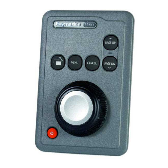
ST70+ Installation Guide Pilot Controller (power boat) keypad Dimensions (overall) 3.62 in (92 mm) x 5.35 in (136 mm) x 2.24 in (57 mm) Buttons Power ( Select Display ( STANDBY AUTO MENU DODGE CANCEL TRACK Rotary Control Rotate to select/adjust Press in to perform OK function Pilot Controller (sail boat) keypad Dimensions (overall) -
Page 67: Index
Index transducers AutoLearn trim tabs Autopilot Documentation aligning the compass (automatic) Drive type aligning the compass (manual) applicability of procedures AutoLearn EMC information check operation checks prior to use counter rudder conformance rudder damping installation guidelines viii rudder gain Enhanced warranty drive type setup open water calibration preliminary procedure... - Page 68 ST70+ Installation Guide instrument system local time align wind transducer magnetic variation linearize wind transducer rudder & motor checks preliminary procedure with rudder reference set wind speed without rudder reference smart transducers rudder limit speed calibration rudder offset speed calibration select language speed calibration conventional transducer...
-
Page 69: Templates
Templates This section provides templates for flush mounting and surface mounting ST70+ keypads. Flush and surface mount templates for the ST70+ displays are provided in a separate document 87107, provided with the product. ST70+ keypad flush mount template ST70+ Keypad FLUSH MOUNT Template Remove material... -
Page 71: Surface Mount
Templates ST70+ keypad surface mount template ST70+ Keypad SURFACE MOUNT Template Cut hole 64 mm (2.1/2 in) diameter Remove material from shaded areas only Drill hole, 5 mm (3/16 in) diameter in 4 positions 57.8 mm (2.27 in) Bezel edge Sun cover edge... - Page 73 Raymarine plc Raymarine Inc. Marine House, 21 Manchester Street, Merrimack, 5 Harbourgate, Southampton Road, Portsmouth, Hampshire PO6 4BQ New Hampshire 03054-4801, United Kingdom. USA. Tel: +44 (0) 23 9269 3611 Tel: +1 603.881.5200 Fax: +44 (0) 23 9269 4642 Fax: +1 603.864.4756 www.raymarine.com...
Need help?
Do you have a question about the ST70+ and is the answer not in the manual?
Questions and answers