Raymarine ST70 User Reference Manual
Autopilot controller
Hide thumbs
Also See for ST70:
- Operating manual (82 pages) ,
- Installation manual (73 pages) ,
- User's reference manual (48 pages)

Related Manuals for Raymarine ST70


Summary of Contents for Raymarine ST70
- Page 1 ST70 Autopilot Controller User Reference Guide Document reference: 81288-2 Date: May 2010...
- Page 3 As correct performance of the boat’s steering is critical for safety, we STRONGLY RECOMMEND that an Authorized Raymarine Service Representative fits this product. You will only receive full warranty benefits if you can show that an Authorized Raymarine Service Representative has installed and commissioned this product.
-
Page 4: Emc Installation Guidelines
In the case of SSB radios, the distance should be increased to 7 ft. (2 m). • Place Raymarine equipment and cables more than 7 ft (2 m) from the path of a radar beam. A radar beam can normally be assumed to spread 20 degrees above and below the radiating element. -
Page 5: Product Disposal
• To minimize any EMC related problems and ensure the best possible perfor- mance from your Raymarine equipment, follow the guidelines given in the instal- lation instructions. Product disposal Waste Electrical and Electronic (WEEE) Directive The WEEE Directive requires the recycling of waste electrical and electronic equipment. -
Page 6: Product Documents
To the best of our knowledge, the information in the product documents was correct when they went to press. However, Raymarine cannot accept liability for any inaccuracies or omissions in product documents. In addition, our policy of continuous product improvement may change specifications without notice. -
Page 7: Table Of Contents
Contents Contents Chapter 1:ST70 Overview ................1 1.1 Functions ....................1 1.2 Display and controls ................2 Controls....................2 Display ....................2 1.3 Operating principles ................3 1.4 System functionality ................4 1.5 Commissioning requirement ..............4 Chapter 2:Setup Procedures ................5 2.1 Using the menu navigation keys ............ - Page 8 ST70 Pilot Controller Reference Guide Waypoint Advance warning ..............30 Route completion.................. 30 3.7 Using the SmartPilot with sail boats ............. 31 Using Wind Vane mode................. 31 What is Wind Vane mode? ..............31 Selecting Wind Vane mode ..............31 Adjusting the locked wind angle ............
-
Page 9: Chapter 1:St70 Overview
Chapter 1: ST70 Overview 1.1 Functions The ST70 Autopilot controller is used to control your autopilot system. It can be used with Raymarine SPX, S1, S2 and S3 SmartPilot systems (although it cannot be used to calibrate an S1, S2 or S3 system). -
Page 10: Display And Controls
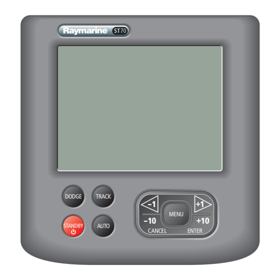
ST70 Pilot Controller Reference Guide 1.2 Display and controls Controls STANDBY When in Standby mode: - Press momentarily to display the Brightness popup. - Hold down to power off. When in Auto mode: Press momentarily to put unit in standby DODGE Activate Dodge mode. -
Page 11: Operating Principles
The ST70 Pilot has two main modes of operation: Standby and Auto. With the ST70 in Standby, the helm is free for manual steering and all setup functions and calibrations can be performed. These settings are stored in the Course Computer. -
Page 12: System Functionality
ST70 Pilot repeats the data on the bus. Power protocol Power to the ST70 Pilot can be switched on and off using the power button. However, where a Pilot is part of a system, it may be more convenient to switch power for the entire system from a central circuit breaker. -
Page 13: Chapter 2:Setup Procedures
• The language. • The time/date format. Refer to the ST70 Autopilot Controller/SmartPilot X Commissioning Instructions for the appropriate procedures. Other setup procedures may be useful on a day-to-day basis. These include: • Changing the screen brightness level. See Brightness on page 7. -
Page 14: Dockside And Open Water Procedures
Compass calibration • Auto learn. 2.3 General setup procedures The setup procedures available depend on the vessel profile as set up during commissioning (Fishing, Sail or Power), and whether the ST70 Pilot is in Standby or Auto mode. Procedure Sail Fishing... -
Page 15: Display Settings
Chapter 2: Setup Procedures Display settings Main Menu MENU 1. Press 2. Use < and > to scroll to the Display Settings ENTER screen and press 3. Use < and > to scroll to the setting you want to Display Settings change. - Page 16 ST70 Pilot Controller Reference Guide Units Display Settings 1. Use < and > to scroll to the Units box and press ENTER Units Change the default unit settings. Press ENTER to select. 2. The summary box shows the current settings.
- Page 17 Chapter 2: Setup Procedures Time and date Display Settings Note that only if a GPS is connected to the system, the time, date and time offset will be retrieved from the GPS and cannot be changed here. Time & Date 1.
- Page 18 ST70 Pilot Controller Reference Guide Data Boxes You can define which data are displayed in each of the three data boxes in the 2D and 3D pilot views. The data that can be displayed (providing it is available) is: Data...
- Page 19 Chapter 2: Setup Procedures 1. Use < and > to scroll to the Data Boxes box and Display Settings ENTER press Data Boxes Select data for the data boxes. Press ENTER to select. 2. Use < and > to scroll to the box whose contents Data Boxes you want to change.
-
Page 20: Autopilot Calibration
< & > adjust response level. CANCEL exits without saving. Press ENTER to accept. Autopilot calibration Refer to the ST70 Autopilot Controller/SmartPilot X Commissioning Instructions. Diagnostics ENTER Use < and > to scroll to the Diagnostics box and press... - Page 21 Chapter 2: Setup Procedures About Display There are a number of parameters of which you may need to make a note if you experience problems with the pilot controller. ENTER 1. Use < and > to scroll to the About Display box and press 2.
-
Page 22: Response Levels
ST70 Pilot Controller Reference Guide 2.4 Response Levels The response level controls the relationship between course keeping accuracy and the amount of helm/drive activity. You can make temporary changes to response during normal operation, as described in Chapter 3:Operating instructions . -
Page 23: Sailboat Setup Procedures
Chapter 2: Setup Procedures 2.5 Sailboat setup procedures Auto Tack Angle The Auto Tack Angle feature allows you to specify Sailboat Settings the angle through which the vessel will tack when you select Auto Tack. MENU 1. Press , then use < and > to scroll to Auto- ENTER pilot Calibration and press Auto Tack Angle... -
Page 24: Wind Trim
ST70 Pilot Controller Reference Guide Wind Trim Wind Trim controls the sensitivity of the pilot when Sailboat Settings steering in wind vane mode. MENU 1. Press , then use < and > to scroll to ENTER Autopilot Calibration and press 2. -
Page 25: Power Boat And Fishing Boat Setup Procedures
Chapter 2: Setup Procedures 2.6 Power boat and fishing boat setup procedures Patterns A number of sailing patterns are provided, each with one or more parameters which can be set to the desired value. MENU 1. Press , then use < and > to scroll to All Main Menu ENTER Patterns and press... - Page 26 ST70 Pilot Controller Reference Guide...
-
Page 27: Chapter 3:Operating Instructions
Steering to true and apparent wind in Wind Vane mode wind in Wind Vane mode wind in Wind Vane mode Equipped with AutoLearn, Equipped with AutoLearn, Raymarine’s self-learning cal- Raymarine’s self-learning cal- ibration system ibration system Fishing patterns Intelligent dodge... -
Page 28: Extended Systems
SeaTalk, NMEA0183, NMEA2000 or SeaTalk instrument data in a selection of data pages. For further information on other connections to your system see ST70 Autopilot Controller/SmartPilot X Commissioning Instructions. 3.2 Menu structure The ST70 pilot controller menu structure varies depending on which Vessel Type has been specified during commissioning and what data is available. -
Page 29: Power And Fishing Boat Menus
Chapter 3: Operating instructions • Vessel Type • Boatshow Mode (simulated data - boat show use only) • Factory Reset • Autopilot Calibration (only when connected to a compatible course computer): • Vessel settings • Drive settings • Sailboat settings •... -
Page 30: Pilot View
ST70 Pilot Controller Reference Guide 3.3 Pilot view The pilot display can be formatted as Plain, 2D or 3D. Setting the default Pilot View 1. Press MENU. ENTER 2. Use < and > to scroll to the Pilot View screen and press 3. -
Page 31: Using The Smartpilot To Steer Your Boat
Chapter 3: Operating instructions 3.4 Using the SmartPilot to steer your boat CAUTION: Maintain a permanent watch Automatic course control makes it easier to sail a boat, but it is NOT a substitute for good seamanship. ALWAYS maintain a permanent watch by the helm. -
Page 32: Using Preset Patterns
ST70 Pilot Controller Reference Guide Using Dodge in Track mode DODGE When in Track mode, press DODGE The DODGE popup will appear over whichever pilot Track from here view you have currently selected. 19.1 DODGE TWS KTS Once you have finished steering manually you can:... -
Page 33: Activating Track Mode
Track mode is available only if you have connected the SmartPilot to a suitable navigation system providing SeaTalk or NMEA information. (See ST70 Pilot Controller/SmartPilot X Commissioning Instructions for connection details) Your SmartPilot system can receive route information from: •... -
Page 34: Leaving Track Mode
ST70 Pilot Controller Reference Guide Start with the SmartPilot in AUTO mode and your chartplotter following a route. TRACK 1. Press to enter Track mode. 2. Wait for the warning to sound. The display will show the bearing to the next planned waypoint and the direction in which the boat will turn to reach this waypoint. -
Page 35: Cross Track Error
Chapter 3: Operating instructions Cross track error Cross track error (XTE) is the distance between the current position and a planned track leg. There are a number of reasons why you may have a cross track error (XTE), for example: •... -
Page 36: Tidal Stream Compensation
ST70 Pilot Controller Reference Guide Tidal stream compensation Under most conditions, the SmartPilot will hold the selected track to within ±0.05 nm (300 ft) or better. It takes account of the boat’s speed when computing course changes to ensure optimum performance. -
Page 37: Steering To The Next Waypoint In A Route
Chapter 3: Operating instructions Waypoint arrival circle The NEXT WPT screen and acknowledgement occur within a circle around the actual waypoint (and hence a distance from the next track leg). If you have manually changed the default waypoint arrival circle value to 0.3Nm or greater this can result in a cross track error alarm and associated course correction. -
Page 38: Waypoint Advance Warning
ST70 Pilot Controller Reference Guide WARNING: Ensure navigation safety Skipping a waypoint will take you straight to the next waypoint. Check your navigation before making the turn. Waypoint Advance warning The SmartPilot activates the Waypoint Advance warning in Track mode whenever the target waypoint name changes. -
Page 39: Using The Smartpilot With Sail Boats
For major changes, return to Standby mode, steer onto the new heading, then reselect Wind Vane mode. Refer to the ST70 Autopilot Controller User Reference Guide for the procedure for changing the wind reference between True and Apparent. -
Page 40: Windtrim
ST70 Pilot Controller Reference Guide The default setting is apparent wind. If required, you can change this to true wind in User Calibration. See Wind Selection on page 16. WindTrim In Wind Vane mode the SmartPilot uses WindTrim to eliminate the effects of turbulence and short term wind variations. -
Page 41: Operating Hints For Wind Vane Mode
Chapter 3: Operating instructions Operating hints for Wind Vane mode • Always trim your sails carefully to minimize the amount of standing helm. • Reef the headsail and mainsail a little early rather than too late. • In Wind Vane mode the SmartPilot will react to long-term wind shifts, but will not correct for short-term changes such as gusts. - Page 42 ST70 Pilot Controller Reference Guide...
-
Page 43: Chapter 4:Maintenance And Troubleshooting
Servicing and safety Unless specific instructions are given to the contrary, Raymarine equipment should be serviced only by authorized Raymarine service technicians. They will ensure that service procedures and replacement parts used will not affect performance. Some products generate high voltages, so never handle the cables/connectors when power is being supplied to the equipment. -
Page 44: Troubleshooting
In the unlikely event that you encounter problems using your ST70 autopilot controller, use this section to resolve the situation. First considerations If your ST70 is not performing as you think it should, be sure you are operating it correctly as described in the ST70 Pilot Operating Guide. Then: •... - Page 45 Return to normal Is the display lit? operation Use the About Display & About System features to get information about your products. Return to Return to Obtain normal normal technical operation operation assistance Figure 4-1 ST70 troubleshooting – Chart 1...
-
Page 46: St70 Pilot Controller Reference Guide
Use the About Display & About System features to get System features to get information about your products. information about your products. Return to Return to Obtain Obtain normal normal technical technical operation operation assistance assistance Figure 4-2 ST70 troubleshooting – Chart 2... -
Page 47: Using The About Display Feature
Figure 4-3 ST70 troubleshooting – Chart 3 Using the About Display feature The About Display function provides information about the instrument on which it is run. Before seeking technical assistance, please use the About Display function whenever possible to find out the relevant: •... -
Page 48: Technical Support
Please visit the Customer Support area of our web site at: www.raymarine.com As well as providing a comprehensive Frequently Asked Questions section and servicing information, the web site gives e-mail access to the Raymarine Technical Support Department and a details of the locations of Raymarine agents, worldwide. -
Page 49: Telephone Help Line
Chapter 4: Maintenance and troubleshooting Telephone help line If you do not have access to the world wide web, please call the Raymarine help line. In the USA, call: • +1 603 881 5200 extension 2444 In the UK, Europe the Middle East or the Far East, call: •... - Page 50 ST70 Pilot Controller Reference Guide...
-
Page 51: Chapter 5:Alarms
STANDBY , or switching to (if in AUTO mode). Press CANCEL to silence alarm SOG KTS The following alarm functions are supported by the ST70, although they may not all be applicable to your system. Alarm Description Action Calibration required The pilot has not been fully cali- Self-cancelling. - Page 52 ST70 Pilot Controller Reference Guide Alarm Description Action Rate gyro fault Safety alarm. Current limit Safety alarm. Rudder feedback unit fault Safety alarm. Autolearn fail 1 (not car- Safety alarm. ried out) Autolearn fail 2 (manual Safety alarm. intervention) Autolearn fail 3 (compass Safety alarm.
-
Page 53: Chapter 6:Data List
Chapter 6: Data List This section lists the data supported by the ST70 Autopilot Controller. Please note that these data are dependent on the configuration of individual systems, so will be not all be available on all systems. Data Group... -
Page 55: Chapter 7:Vessel Settings
Chapter 7: Vessel Settings The following table gives possible values for the various vessel settings and their effect on performance. For full details refer to the ST70 Autopilot Controller/ SmartPilot X Commissioning Instructions. Setting Effect Values Default Auto Release Allows manual override on Auto mode... - Page 56 ST70 Pilot Controller Reference Guide...
-
Page 57: Chapter 8:Technical Specifications
Chapter 8: Technical specifications Supply voltage 12 V dc (nominal) 16 V dc (maximum) 9 V dc (minimum) Current Nominal: dependent upon screen brightness Maximum: not more than 220 mA Physical dimensions 4.33(W) x 4.53 (H) x 1.28 (D) (excluding studs) 110 mm x 115 mm x 32.5 mm Weight 250 g (approx.) - Page 58 ST70 Pilot Controller Reference Guide...
- Page 59 Index display response level, response level, About Display function, steer to, Alarms, units, Apparent wind, Help lines, Auto mode, changing course, Auto Tack, Language change angle, setting, Auto Tack Angle, Menu Cable checking, mode, Chartplotter navigation keys, following a track, structures, Cleaning, Controls,...
- Page 60 ST70 User Reference Manual Specifications, display response level, Speed Wind Speed display response level, display response level, response level, Wind Trim, units, change sensitivity, Speed, wind Wind vane mode, units, Technical support, Temperature units, Tidal stream compensation, Time format, offset,...
Need help?
Do you have a question about the ST70 and is the answer not in the manual?
Questions and answers
ON STARTUP ST70 STATING NO PILOT