
Related Manuals for Honeywell GSMX


Summary of Contents for Honeywell GSMX
- Page 1 800-04432 9/09 Rev. B...
-
Page 2: Table Of Contents
Contents General Information ................... 1 Features......................1 Modes of Operation ..................1 Supervision and Fault Detection ..............2 Specifications....................2 Data Encryption ..................... 2 Remote Services Features................2 Testing the System..................3 Compatibility ....................3 Compliance ..................... 3 Mounting and Wiring the Module ..............3 Select a Mounting Location ................ -
Page 3: General Information
GSMX Installation and Setup Guide General Information The GSMX GSM Communicator (also herein referred to as the module) easily connects to your security system's control panel and sends alarms and messages to AlarmNet for subsequent transfer to the central monitoring station. -
Page 4: Supervision And Fault Detection
KEY used to encrypt the data. Each device produced by Honeywell is loaded with a unique identifier called a MAC number, and a large random number or KEY. This KEY and MAC number are also stored in the AlarmNet servers. -
Page 5: Testing The System
After installation the security system should be tested. Refer to the control panel installation instructions for procedures to test the entire system. Compatibility The GSMX functions with any control panel that utilizes a Honeywell ECP bus and supports Long Range Radio. Compliance This device has been tested by ETL to meet the following standards: •... -
Page 6: Activating The Sim
Ensure power to the control panel (both AC and battery) is off. Open the enclosure and connect the ECP cable to the GSMX module. Temporarily attach the Black and Red wires to the GND and AUX PWR terminals of the control panel. DO NOT connect the Yellow and Green wires at this time. -
Page 7: Mounting The Module On The Control Panel
Ensure power to the control panel (both AC and battery) is off, then remove the knockout on the top right of the control panel cabinet. Open the GSMX cover. Remove the Hole Cap attached to the plastic (trim as necessary), and snap it into the top opening of the enclosure. -
Page 8: Mounting The Module On The Wall
Open the GSMX cover. Remove the Hole Cap attached to the plastic (trim as necessary), and snap it into the top opening of the enclosure. Secure the enclosure to the wall using both mounting holes. - Page 9 GSMX Installation and Setup Guide Connect the ECP cable to the GSMX circuit board. When mounting the GSMX off the cabinet, the length of the supplied ECP cable will have to be spliced to a four-wire extender cable. Ensure the splices are located within the GSMX's enclosure.
-
Page 10: Programming The Module
ECP cable wiring. Secure the wiring with ties as necessary. Programming the Module The GSMX requires an AlarmNet account. For new installa- tions, please obtain the account information from the central station prior to programming this module. You can program the communications module by one of the following methods: •... -
Page 11: Using The 7720P Programming Tool
GSMX Installation and Setup Guide Using the 7720P Programming Tool Ensure the GSMX is powered, and connect the 7720P Programming Tool. TEST MESSAGE/REGISTRATION Switch Each key has two possible functions; a Normal function and a Shift function. • To perform a Normal key function, simply press the desired key. -
Page 12: Programming Conventions
GSMX Installation and Setup Guide SPACE [SPACE]: For scrolling option list No SHIFT function [0]: For entering the number 0 No SHIFT function #/ENTE [#/ENTER]: Starts programming No SHIFT function mode; Press to accept entries * Active only when the "Exit Programming Mode" prompt is displayed. -
Page 13: Programming For 4204 And Two-4204 Emulation Modes
4204s using consecutive device addresses. The compatible Honeywell VISTA series or First Alert control panel sends data (triggers) to the communications module as if it were a 4204 module. (The control panel must be configured to recognize one or two 4204 relay modules accordingly.) On VISTA-32FB (or higher) control panels and First... - Page 14 GSMX Installation and Setup Guide 4204 Relay Outputs map to zones First 4204 Zones (device Second 4204 Zones (device address address entered in Prompt 15): entered in Prompt 15, plus 1): Relay 1 = Zone 1 Relay 1 = Zone 5...
-
Page 15: Programming Options
GSMX Installation and Setup Guide Programming Options NOTE: The default programming values are listed in the prompts below. PROMPTS ENTRY OPTIONS DESCRIPTION [Y], [N] Enters programming mode. Strt Prog Mode? (Y/N)_ [0-9, A-F, If a password has been previously Enter N, S, T, X, assigned, this prompt appears. - Page 16 GSMX Installation and Setup Guide PROMPTS ENTRY OPTIONS DESCRIPTION [Y], [N] If a password has already been Change Password? assigned, this prompt appears after pressing [N] at the (Y/N)_ "Program Device?" prompt. Press [Y] if you want to change the password.
- Page 17 When programming the GSMX, at prompt #10, choose 4204-Sourced so the user can be notified of up to four events, or choose 2-4204-Sourced so the user can be notified of up to eight system events.
- Page 18 • Remote Access must be enabled by selecting "Enabled" at the Remote Access prompt. • A keypad address must be enabled in the GSMX in order for the module to communicate with the control panel. • At the “Keypad Type” prompt, select the appropriate Keypad.
- Page 19 GSMX Installation and Setup Guide PROMPTS ENTRY OPTIONS DESCRIPTION • 30 Day The AlarmNet network must hear Supervi- sion at least one supervisory message • 24 Hour from the module during this • None supervision period; otherwise, Hours)_ AlarmNet notifies the central station that a communication failure has occurred.
-
Page 20: Ecp Status Codes
Exiting Programming Mode topic. ECP Status Codes The GSMX sends status messages to the control panel to report various failures. Some control panels, (e.g., VISTA-10P, VISTA-15P and VISTA-20P Series) display these status codes on the keypad as “LngRng Radio” followed by a 4-digit code. -
Page 21: Exiting The Programming Mode
If critical configuration changes were made, such as the mode of operation, the GSMX will reset to ensure that the programming features are enabled. If the file is not successfully uploaded, one of the following prompts will be displayed. -
Page 22: Registering The Module
“E339 803”. The description may read “Trouble – Exp. Mod. Reset”. If registration is not validated within 90 seconds, the GSMX times out, and the REG (green) LED will be lit solid. Registering through the AlarmNet Direct Website To register the module via the website, go to: https://services.alarmnet.com/AlarmNetDirect... -
Page 23: Remote Services
REGISTRATION Switch Registering Using the Programming Tool The interactive registration feature allows the installer to register the GSMX through a series of keyboard commands on the 7720P Programming Tool. This method of registration lets the installer monitor the registration process. -
Page 24: Replacing An Existing Module Using The Programming Tool
The registration message is sent and the unit waits for Registering acknowledgement. … If the PIN is valid, the new GSMX is registered and the old Registration unit unregistered. Additionally, AlarmNet sends a SUCCESS substitution alarm to the central station. -
Page 25: Registering By Phone
GSMX Installation and Setup Guide Registering by Phone You can register the module by calling the AlarmNet Support at 1-800-222- 6525 (Option 1). You will need the following information: • MAC ID and CRC (located on outside of box and on label inside module). -
Page 26: Gsm Status Displays
GSMX Installation and Setup Guide Time Mon 01 Jan Retrieves the current date and time from the 2001 AlarmNet network in Greenwich Mean Time 05:48:39 am (GMT). This display confirms that the module is in sync with network. Encryption Test... - Page 27 NOT yet expired. Test Alarm Test Msg Sent Sends a Test alarm to AlarmNet. Functional for a registered GSMX only. If the device is not registered, a message is displayed indicating that the command cannot be executed. Reset the GSMX. Reset CPU Pressing [N] returns to normal mode.
-
Page 28: Central Station Messages
GSMX Installation and Setup Guide Force Upload of Configuration File to Force Server Server Update? Pressing [Y] will force the device to upload its entire configuration file to the server. Pressing [N] cancels the operation. NOTE: If the GSM module is not initialized... -
Page 29: Uploading And Downloading Of Panel Data
NOTE: For UL, downloading may only be performed if a technician is at the site. The GSMX can be used to provide high-speed up/downloading to control panels (that support this feature) over the GPRS network via ECP communication. This allows site maintenance independent of central station monitoring, and modification to sites globally. - Page 30 NOTES...
-
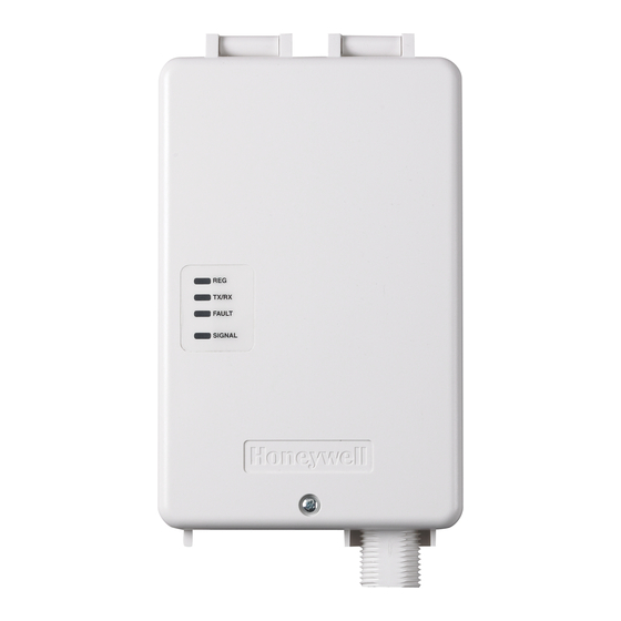
Page 31: Led And Wiring Information
LED and Wiring Information DESCRIPTION ON – Module is NOT registered with AlarmNet. (green) OFF – Module is registered with AlarmNet. FAST BLINK – Download session with Compass in progress. SLOW BLINK – In unison with yellow LED – Registration in progress. TX/RX ON –... - Page 32 For the latest documentation and online support information, please go to: http://www.security.honeywell.com/hsc/resources/MyWebTech/ WARRANTY For the latest warranty information, please go to: http://www.security.honeywell.com/hsc/resources/wa/ 2 Corporate Center Drive, Suite 100, P.O. Box 9040, Melville, NY 11747 Copyright © 2009 Honeywell International Inc. www.honeywell.com/security Ê800-04432zŠ 800-04432 9/09 Rev. B...
Need help?
Do you have a question about the GSMX and is the answer not in the manual?
Questions and answers