Honeywell IntelliPath Series Installation And Setup Manual
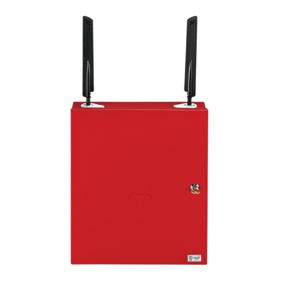
Commercial fire panel internet and cellular communicator
Hide thumbs
Also See for IntelliPath Series:
- Installation and setup manual (64 pages) ,
- Installation and setup manual (64 pages)
Table of Contents
Advertisement
800-24454 9/18 Rev A
I
n
t
I
n
t
C
o
m
m
e
r
c
i
a
l
F
i
r
e
C
o
m
m
e
r
c
i
a
l
F
i
r
e
e
l
l
i
P
a
t
h
S
e
e
l
l
i
P
a
t
h
S
e
T
M
T
M
P
a
n
e
l
I
n
t
e
r
n
e
t
P
a
n
e
l
I
n
t
e
r
n
e
t
Installation and Setup Guide
r
i
e
s
C
o
m
m
r
i
e
s
C
o
m
m
L
T
E
L
T
E
L
T
E
L
T
E
a
n
d
C
e
l
l
u
l
a
r
C
o
m
a
n
d
C
e
l
l
u
l
a
r
C
o
m
u
n
i
c
a
t
o
r
u
n
i
c
a
t
o
r
-
C
F
V
-
C
F
V
-
C
F
A
-
C
F
A
m
u
n
i
c
a
t
o
r
m
u
n
i
c
a
t
o
r
Advertisement
Table of Contents

Subscribe to Our Youtube Channel
Related Manuals for Honeywell IntelliPath Series


Summary of Contents for Honeywell IntelliPath Series
- Page 1 Installation and Setup Guide 800-24454 9/18 Rev A...
-
Page 3: Table Of Contents
Table of Contents SECTION 1: General Information ........................ - Page 4 LTE-CF Installation and Setup Guide SECTION 5: Programmer Keyboard Commands ..................21 Identification Displays ..........................21 Cell Status Displays ............................ 22 System Status Display ..........................25 SECTION 6: Network Diagnostics ......................... 27 Running Network Diagnostics ........................27 ...
-
Page 5: Section 1: General Information
If, for some reason, Internet connectivity is not available, (for example, your customer's ISP is off line or disconnected), the communicator will transmit signals via the cellular network. These transmissions are sent to the Honeywell NOC and then forwarded to your Central Station exactly the same way as if they were received via the Internet. -
Page 6: System Features
The communicator uses 256 bit AES (Rijndael) encryption (which is required for certain government installations). The AlarmNet-i AES Encryption Software Module Version 1.0 contained in the Honeywell products has NIST approval. Listings for this approval can be found at https://csrc.nist.gov/projects/cryptographic-algorithm-validation-program/validation/validation- list/aes and search for “Certification number 979.”... -
Page 7: Specifications
Section 1: General Information Specifications Mechanical: Dimensions: 15.0"H x 12.75" W x 3.0" D Weight: 10 lbs. 12VDC supplied by the Control Panel. Input Power: Current Drain: 90mA (rms) standby, 105mA (rms) active Network Standard: IEEE 802.3u compliant Ethernet: Data Rate: 10Base-T / 100Base-T with auto detect Ethernet Cable: Cat. -
Page 8: Compatibility
LTE-CF Installation and Setup Guide Compatibility UL – Compatible Control Panels VISTA-32FB FA1670C (First Alert) VISTA-32FBT FA1670CT (First Alert) VISTA-128FBP FA1700C (First Alert) VISTA-128FBPT FA1700CT (First Alert) VISTA-250FBP VISTA-250BPT UL – Compatible Receivers 7810iR-ENT Must be the primary alarm receiver. 8810iR Must be the primary alarm receiver. -
Page 9: Section 2: Mounting And Wiring
S E C T I O N Mounting and Wiring Determine the Signal Quality and Select a Location The communicator must be mounted indoors within the protected premises. -
Page 10: Mount The Communicator
LTE-CF Installation and Setup Guide Mount the Communicator This communicator comes fully assembled with all the components mounted except the external Antenna, and Antenna Mounting Adapter. Refer to the Wiring Diagram on the inside of the back cover for wiring and component identification. -
Page 11: Wire The Communicator
A UL listed control panel must monitor the radio fault output of the communicator. Most Honeywell control panels support ECP data communication. Check the Installation and Setup Guide for the control panel you are using to see if it supports ECP communication. -
Page 12: Wire The Internet Connection
LTE-CF Installation and Setup Guide Wire the Internet Connection For UL installations, the Ethernet connection between the communicator and the router can- not exceed 20 feet with both the communicator and the router located within the same room. All equipment used for the IP connection (such as the router, hub, modem, etc.) shall be listed, must be powered from an un-switched branch circuit, and be provided with appropriate standby power. -
Page 13: Section 3: Programming The Communicator
S E C T I O N Programming the Communicator General Information The communicator is designed to deliver alarms via the Internet to an AlarmNet central station or via the cellular network when the Internet is not available. -
Page 14: Programming For Ul864 Compliance
LTE-CF Installation and Setup Guide Programming for UL864 Compliance This communicator provides a programmable supervision feature that allows the system to meet the UL864 Commercial Fire requirements. These requirements are in the following table. NOTICE TO USERS, INSTALLERS, AUTHORITIES HAVING JURISDICTION AND OTHER INVOLVED PARTIES This product incorporates field programmable software. -
Page 15: Using A 7720P Programming Tool
Section 3: Programming the Communicator Using a 7720P Programming Tool Connect the 7720P Programming Tool as shown below. The communicator powers the 7720P Programming Tool via the programming jack, and automatically senses the presence of the 7720P when it is plugged in. 7720P PROGRAM CONNECTOR... -
Page 16: Programming Conventions
LTE-CF Installation and Setup Guide Programming Conventions Programming is accomplished by answering a series of prompts. Most prompts require only a [Y]es or [N]o response, while others require a numerical response (ID numbers, etc.). The current value is displayed on the second line in parentheses ( ). A "?" indicates an invalid entry. - Page 17 Section 3: Programming the Communicator PROMPTS OPTIONS DESCRIPTION [Y], [N] Exits program mode. Exit Prog. Mode? (Y/N)_ Press [N] to go back to Prompt 3. [ESC] Press [ESC] to load factory defaults. Refer to the Exiting Programming Mode paragraph in this section. 2010 IP &...
- Page 18 LTE-CF Installation and Setup Guide PROMPTS OPTIONS DESCRIPTION This prompt appears only if comm. path includes IP&Cell or Cell. Cell Flt Time [00-60] (60 mins) Enter the time delay (1 – 60) in minutes before the communicator notifies the control panel that there is a communication path failure to AlarmNet over the hard-wired Ethernet connection.
-
Page 19: Exiting Programming Mode
Section 3: Programming the Communicator Exiting Programming Mode To exit the programming mode, press [N] in response to the "REVIEW?" prompt. Then press [Y] to the "Exit Prog Mode?" prompt. Upon exiting, the root file is updated to log the changes made. A message is displayed telling the user that this step is being executed. -
Page 21: Section 4: Registration
S E C T I O N Registration Registering the Communicator Once you have programmed the communicator, it must be registered to enable the AlarmNet account. -
Page 22: Register Using The Test / Registration Switch
LTE-CF Installation and Setup Guide Register using the TEST / REGISTRATION Switch Initiate the registration sequence by clicking the TEST / REGISTRATION switch three times. You can monitor the registration process by viewing the Status Display. The Message (yellow) LED and the Status (green) LED will blink slowly in unison while registration is in progress. Once the registration has been completed successfully, the communicator enters normal operating mode;... -
Page 23: Replacing An Existing Communicator
Section 4: Registration Replacing an existing communicator This prompt appears after pressing the [Shift] and down arrow [] on Enter PIN# the 7720P. NOTE: If it is necessary to exit registration mode, press ESC from the 7720P programming tool. Enter a 4-digit alphanumeric PIN number provided by your central station, your dealer or an authorized AlarmNet representative. - Page 24 LTE-CF Installation and Setup Guide...
-
Page 25: Section 5: Programmer Keyboard Commands
S E C T I O N Programmer Keyboard Commands Programmer keyboard commands can be used to quickly view your connectivity settings and options. -
Page 26: Cell Status Displays
LTE-CF Installation and Setup Guide IP Information Display NIC IP Address Displays the IP address assigned to this device. xxx.xxx.xxx.xxx Press the [Space] key to go to the next field. NOTE: The Subnet Mask, Gateway IP Addr, DSN Serv IP and DHCP are only displayed if the Comm Path Choice is “IP&Cell”... - Page 27 Section 5: Programmer Keyboard Commands LTE Displays Signal Display for LTE RAT RSRP RSRQ RAT – Radio Access Technology. xxxx xxxx RSRP – Reference Signal Received Power RSRQ – Reference Signal Received Quality Press the [space] key to get to the next screen. Press the [backspace] key to go to the previous field.
- Page 28 LTE-CF Installation and Setup Guide Operating with 3G Service Signal Display for 3G RAT RSCP EC/No RAT – Radio Access Technology. -xxx -xxxxxx RSCP –Received Signal Code Power Ec/N0 – Carrier Noise Ratio (CNR) Press the [space] key to get to the next screen. Press the [backspace] key to go to the previous field.
-
Page 29: System Status Display
Section 5: Programmer Keyboard Commands System Status Display ECP Mode Displays the system status. Flt – Represents radio faults: OK = Normal ; No fault I – No network connectivity over IP and fault time has expired i – No network connectivity over IP and fault time has NOT yet expired. - Page 30 LTE-CF Installation and Setup Guide...
-
Page 31: Section 6: Network Diagnostics
S E C T I O N Network Diagnostics Running Network Diagnostics The network diagnostic process tests the integrity of the links between the communicator and the various connection points of AlarmNet Control that are known as "REDIRECTORS"... -
Page 32: Possible Errors Running Network Diagnostics
LTE-CF Installation and Setup Guide Possible Errors Running Network Diagnostics Errors may occur either while tracing the connection to a given Redir or while testing the service at a given Redir. The following list highlights the most common errors. Please contact the AlarmNet Technical Assistance Center (TAC) for help regarding any errors NOT listed below: Possible Errors While tracing the connection to Redir x, the trace fails before ever... -
Page 33: Appendices
Appendices Appendix A: Summary of LED Operation LTE-CF-001-V0... - Page 34 LTE-CF Installation and Setup Guide...
-
Page 35: Appendix B: Central Station Messages
Appendices Appendix B: Central Station Messages ECP Mode Alarm Condition Alarm Code Restore Code Power On / Reset E339 C08xx* ECP Supervision E355 C0000 R355 C0000 (Compromise Indication) Primary Comm Path Supervision E350 C0951 R350 C0951 Secondary Comm Path Supervision E350 C0952 R350 C0952 Periodic Cell Comm Test Failure... - Page 36 LTE-CF Installation and Setup Guide...
-
Page 37: Appendix C: Glossary
(e.g., www.yahoo.com) into numerical IP addresses (e.g., 204.17.25.1.). Digital Subscriber Line. Enhanced Console Protocol, which is a proprietary bus used in Honeywell control panels to communicate with keypads and peripheral devices. It uses four wires; power, ground, data in, data out. - Page 38 LTE-CF Installation and Setup Guide...
-
Page 39: Wiring Diagram
Wiring Diagram ANTENNAS NUT, WASHER ANTENNA MOUNTING ADAPTER CABINET DOOR FACTORY USE ONLY STATUS SIGNAL CELLULAR QUALITY / MESSAGE 7720P STATUS LED MODE PROG. PORT FAULT STATUS LEDs TB 1 TEST/ REGISTRATION MODE SWITCH SWITCH To Facility Ground NETWORK TB 1 CONNECTIVITY LEDs NOT USED... - Page 40 (2) This device must accept any interference received, including interference that may cause undesired operation. Responsible Party / Issuer of Supplier’s Declaration of Conformity: Honeywell International, 2 Corporate Center Drive., Melville, NY 11747, Ph: 516-577-2000 RF Exposure Warning –...
Need help?
Do you have a question about the IntelliPath Series and is the answer not in the manual?
Questions and answers