Honeywell HW-AV-LTE-M Product Installation Document
Clss pathway
Hide thumbs
Also See for HW-AV-LTE-M:
- Installation and operation manual (30 pages) ,
- Quick start manual (2 pages) ,
- Product installation document (6 pages)
Advertisement
HW-AV-LTE-M
CLSS Pathway
Product Installation Document
Overview
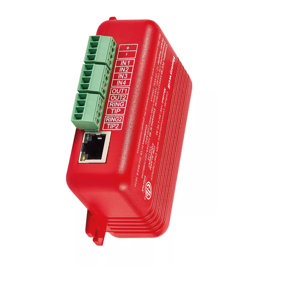
The CLSS Pathway (HW-AV-LTE-M) is a dual-path cellular communicator, which runs on a 24-volt power
from its panel. It supports both AT&T and Verizon LTE networks, and uses any of them with a stronger signal.
It transmits Contact ID data from its fire panel to the panel's central monitoring station.
This document includes instructions for mounting and wiring only. For this purpose, the guide uses the optional
enclosure HW-AV-ENC.
Other Features
The communicator also has other features, including secondary data transmission via an Ethernet connection as
well as monitoring dry-contact relay outputs.
Information Sources
For more detailed procedures and all configuration options:
Installation and Operation Manual (LS10340-000HW-E)
For quickly install and configure CLSS Pathway, refer to the Quick Start Guide (LS10339-000HW-E), which
comes with the communicator.
To access the most updated versions of all product documentation, log on to CLSS Site Manager and access
the help section.
A. Mounting the Communicator
NOTES:
Inform the central monitoring station to put your CLSS Account on test.
If installing on an existing operational panel, inform the operator and the local authority that the panel will be
a temporarily out of service.
Check that you have the communicator, 3-ft antenna, and the Quick Start Guide from the carton box.
Only a regulated UL-listed UOJZ, UTOU, or NBSX control panel or power supply should power the
communicator.
The communicator must be connected to a UL-listed control panel with power limited circuits.
For UL installations, secure the communicator to a UL-listed enclosure, such as a UL-listed junction box.
Install the communicator only at a dry indoor location.
The location and wiring methods must be in accordance with the National Electrical code, ANSI/NFPA 70.
Install in accordance with the National Fire Alarm and Signalling Code, NFPA 72.
Mount the communicator inside an enclosure, for example HW-AV-ENC, as shown in Figure 1 below.
Enclosure should be close nipple to the fire alarm control panel.
1
Advertisement
Table of Contents

Related Manuals for Honeywell HW-AV-LTE-M


Summary of Contents for Honeywell HW-AV-LTE-M
- Page 1 Product Installation Document Overview The CLSS Pathway (HW-AV-LTE-M) is a dual-path cellular communicator, which runs on a 24-volt power from its panel. It supports both AT&T and Verizon LTE networks, and uses any of them with a stronger signal. It transmits Contact ID data from its fire panel to the panel’s central monitoring station.
-
Page 2: Before Mounting
Before Mounting 01. Know whether to install CLSS Pathway for dialer capture or for panel relay monitoring. 02. If it is for dialer capture, know whether to install the CLSS Pathway with LAN (dual-path communications) or without LAN (sole path) 03. -
Page 3: Installing The Antenna
B. Installing the Antenna The antenna comes with an SMA connector, which provides easy connection with the communicator. IMPORTANT Do not use a damaged antenna with the communicator. Replace the damaged antenna immediately. Use only a manufacturer approved antenna. Non-approved antennas or modifications could impair service ... - Page 4 To Wire the Panel with the Communicator Panel’s Panel’s Terminal Connections at CLSS Pathway Connector Connect to + Connect to - RING Connect to RING Primary Dialer Connect to TIP RING2 Connect to RING2 Backup Dialer TIP2 Connect to TIP2 CAUTION DO NOT USE RESETTABLE POWER TERMINALS.
- Page 5 Wiring for Dry Contact Relay Outputs The communicator can be wired to monitor dry contact relay outputs. This wiring is done without connecting to a dialer interface. CAUTION All wiring must be within a conduit. Do not use resettable power terminals. To Wire for the Dry Contact Relay Outputs 01.
- Page 6 Figure 3: Wiring for Dry Contact Relay Monitoring Powering ON 01. Power ON the communicator and the panel. 02. Ensure that the panel and the communicator are receiving power. 03. Ensure that the Green LED on the communicator is continuously ON indicating successful connections. NOTE: Refer to the Troubleshooting section if there is an issue and to resolve it.
- Page 7 D. Programming the Connected Panel Program according to the panel’s programming document. Enable the PSTN dialer of the panel Select the DTMF mode (for tone dialing) Select the Contact ID communication format Provide any telephone number for dialing. Ex: 999999 ...
-
Page 8: Troubleshooting
Troubleshooting Connection Troubles Resolved Status Indication: The Communicator LED starts flashing. Continuous ON indicates a good connection. LED Status Possible Causes Corrective Actions The communicator is not connected to the Ensure that the wirings are as per the wiring panel. - Page 9 Go to the Device Registration screen in the CLSS App. Cellular connectivity issues Ensure that the signal strength shown on it is at least one to two bars. Reposition the antenna for higher signal strength. Honeywell Security & Fire 12 Clintonville Road Northford, CT 06472-1610 203.484.7161...
Need help?
Do you have a question about the HW-AV-LTE-M and is the answer not in the manual?
Questions and answers