
Related Manuals for Motorola NVG510


Summary of Contents for Motorola NVG510
- Page 1 Administrator’s Handbook Motorola Embedded Software Version 9.0.6 ® Motorola NVG510 Voice Gateway ®...
- Page 2 (such as translation, transformation, or adaptation) without written permission from Motorola Mobility, Inc. Motorola reserves the right to revise this publication and to make changes in content from time to time without obligation on the part of Motorola to provide notification of such revision or change. Motorola pro- vides this guide without warranty of any kind, implied or expressed, including, but not limited to, the implied warranties of merchantability and fitness for a particular pur-...
-
Page 3: Table Of Contents
....14 Set up the Motorola Gateway ......16 Accessing the Web Management Interface . - Page 4 Administrator’s Handbook Working with Packet Filters ........51 NAT/Gaming .
- Page 5 Cuidando do meio ambiente através da reciclagem ... . . 143 Var rädd om miljön genom återvinning......143 ® Motorola Gateway Captive Portal Implementation 145 Appendix A Overview .
- Page 6 Administrator’s Handbook...
-
Page 7: Chapter 1 Introduction
Gateway acts as a pass-through device and allows the workstations on your LAN to have public addresses directly on the Internet. Motorola, Inc. provides a suite of technical information for its family of intelligent enterprise and consumer Gate- ways. It consists of: Administrator’s Handbook... -
Page 8: Documentation Conventions
Denotes an area of emphasis on a Web page solid rounded rectangle with an arrow Command Line Interface Syntax conventions for the Motorola Gateway command line interface are as follows: Convention Description straight ([ ]) brackets in cmd line Optional command arguments... -
Page 9: Organization
It gives a table of conventions. ® Chapter 2, “Device Configuration” — Describes how to get up and running with your Motorola Gateway. Chapter 3, “Basic Troubleshooting” — Gives some simple suggestions for troubleshooting problems with your Gateway’s initial configuration. - Page 10 Administrator’s Handbook...
-
Page 11: Chapter 2 Device Configuration
Most users will find that the basic Quick Start configuration is all that they ever need to use. The Quick Start sec- ® tion may be all that you ever need to configure and use your Motorola Gateway. For more advanced users, a rich feature set is available. -
Page 12: Important Safety Instructions
POWER SUPPLY INSTALLATION ® Connect the power supply cord to the power jack on the Motorola Gateway. Plug the power supply into an appro- priate electrical outlet. There is no power (on / off) switch to power off the device. -
Page 13: Wichtige Sicherheitshinweise
Wichtige Sicherheitshinweise NETZTEIL INSTALLIEREN ® Verbinden Sie das Kabel vom Netzteil mit dem Power-Anschluss an dem Motorola Gateway. Stecken Sie dann das Netzteil in eine Netzsteckdose. Warnung: Das Netzteil muss an eine Steckdose, die mit einem Schutzleiter verbunden ist, angeschlos- sen werden. -
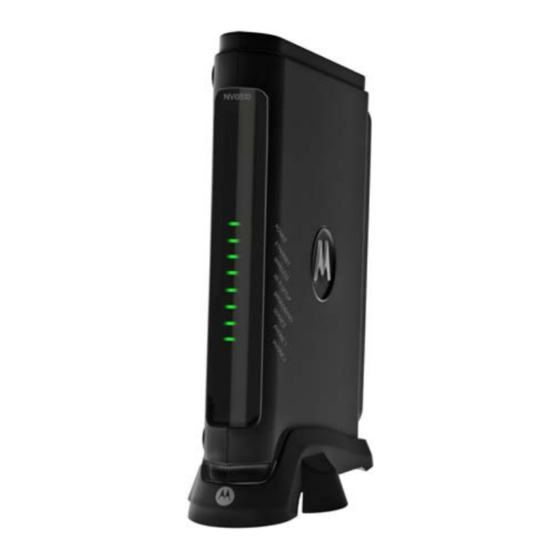
Page 14: Motorola ® Gateway Status Indicator Lights
Administrator’s Handbook ® Motorola Gateway Status Indicator Lights ® Colored LEDs on your Motorola Gateway indicate the status of various port activity. Motorola® Gateway NVG510 status indicator lights Side View Power Ethernet Wireless Wi-Fi Setup Broadband Service Phone 1 Phone 2... - Page 15 Phone 1, 2 Flashing Green = Indicates a telephone is off-hook on the associated VoIP line. Off = VoIP not in use, line not registered or Gateway power off. Motorola® Gateway NVG510 Rear View DSL Port Ethernet Ports WPS Pushbutton...
-
Page 16: Set Up The Motorola Gateway
Set up the Motorola Gateway ® Refer to your Quickstart Guide for instructions on how to connect your Motorola gateway to your power source, PC or local area network, and your Internet access point, whether it is a dedicated DSL outlet or a DSL or cable ®... - Page 17 . Windows Vista and Windows 7 obtain an IP address automatically by default. You may not need to configure it at all. To check, open the Networking Control Panel and select Internet Protocol Version 4 (TCP/IPv4). Click the Properties button. The Internet Protocol Version 4 (TCP/IPv4) Properties window should appear as shown.
- Page 18 Administrator’s Handbook Macintosh MacOS 8 or higher or Mac OS X: Step 1. Access the TCP/IP or Network control panel. . MacOS follows a path like this: Apple Control Panels TCP/IP Menu -> -> Control Panel . Mac OS X follows a path like this: Apple System Preferences Network...
-
Page 19: Accessing The Web Management Interface
Accessing the Web Management Interface Run your Web browser application, such as Firefox or Microsoft Internet Explorer, ® from the computer connected to the Motorola Gateway. Enter http://192.168.1.254 in the Location text box. The Device Status Page appears. GREEN Check to make sure the Broadband and Service LEDs are lit to verify that the connection to the Internet is active. - Page 20 Administrator’s Handbook IP Diagnostics page In the event that your connection to the Internet fails, the IP Diagnostics page displays. Follow the on-screen troubleshooting suggestions. For additional troubleshooting information, see “Basic Troubleshooting” on page...
-
Page 21: Device Status Page
Device Status page ® After you have performed the basic Easy Login configuration, any time you log in to your Motorola Gateway you ® will access the Motorola Gateway Home Page. http://192.168.1.254 You access the Home Page by typing in your Web browser’s location box. - Page 22 Administrator’s Handbook The Device Status displays the following information in the center section: Field Description Broadband Broadband Connection ‘Waiting for DSL’ is displayed while the Gateway is training. This should change to ‘Up’ within two minutes. ‘Up’ is displayed when the ADSL line is synched and the PPPoE ses- sion is established.
-
Page 23: Tab Bar
Tab Bar The tab bar is located at the top of every page, allowing you to move freely about the site. The tabs reveal a succession of pages that allow you to manage or configure several features of your Gateway. Each tab is described in its own section. -
Page 24: Links Bar
Administrator’s Handbook Links Bar The links bar at the top of each page allows you to configure different aspects of the features displayed on the page. For example, on the Home Summary page, the button bar is shown below: Click the links below to be taken to each section. “Device Status page”... -
Page 25: System Information
Link: System Information System Information link, the System Information page appears. When you click the The page displays the following information: System Information Manufacturer This is the manufacturer’s identifier name. Model Number This is the manufacturer’s model number. Serial Number This is the unique serial number of your Gateway. -
Page 26: Access Code
Administrator’s Handbook Link: Access Code Access to your Gateway is controlled through an account named Admin. The default Admin password for your Gateway is the unique Access Code printed on the label on the side of your Gateway. As the Admin, you can change this password to a different one of your own choosing up to 32 characters long. The new password must also include two characters from any these categories: alpha, number, and special char- acters. -
Page 27: Restart Device
Link: Restart Device When the Gateway is restarted, it will disconnect all users, initialize all its interfaces, and load the Operating Sys- tem Software. When you make configuration changes, you may be required restart for the changes to take effect. -
Page 28: Broadband
Administrator’s Handbook Broadband Broadband tab, the Broadband Status page appears. When you click the The Broadband Status page displays information about the Gateway’s WAN connection to the Internet. Broadband Status Line State May be Up (connected) or Down (disconnected). Broadband Connection May be Up (connected) or Down (disconnected). - Page 29 Gateway IPv4 Address Your ISP's gateway router IP address. MAC Address Your Gateway’s unique hardware address identifier. Primary DNS The IP Address of the Primary Domain Name Server. Secondary DNS The IP Address of the backup Domain Name Server, if available. Primary DNS Name The name of the Primary Domain Name Server.
-
Page 30: Configure
Administrator’s Handbook Link: Configure Configure link, the Broadband Configure screen appears. When you click the The WAN connection is automatically configured. However, you can adjust the MTU (Maximum Transmittable Unit) value, if your service provider suggests it. The default 1500 is the maximum value, but some services require other values. -
Page 31: Home Network
Home Network Home Network tab, the Home Network Status page appears. When you click the The Home Network Status page displays information about the Gateway’s local area network. - Page 32 Administrator’s Handbook Home Network Status Device IPv4 Address The Gateway’s own IP address on the network. DHCP Netmask The Gateway’s own netmask on the network. DHCPv4 Start Address The starting IP address of the DHCP range served by the Gateway. DHCPv4 End Address The ending IP address of the DHCP range served by the Gateway.
-
Page 33: Configure
ERP-PBCC Status This tells whether or not the Gateway is honoring legacy 802.11b compatibility mode. This is the wireless modulation in use. DSS if in b-only mode, OFDM other- DSSS-OFDM Status wise. May be either On or Off. If On, you can accept or block client devices from MAC Address Filtering your WLAN based on their MAC address. - Page 34 Administrator’s Handbook Link: Configure Configure link, the Configure page for the Ethernet LAN appears. When you click the For each Ethernet Port, 1 through 4, you can select: Ethernet – auto (the default self-sensing rate), 10M full- or half-duplex, 100M full- or half-duplex, or 1G full- or half-duplex.
-
Page 35: Wireless
Link: Wireless Wireless When you click the link the Wireless page appears. The Wireless page displays the status of your Wireless LAN elements. The Wireless page’s center section contains a summary of the Wireless Access Point’s configuration settings and operational status. Summary Information Field Status and/or Description... - Page 36 Administrator’s Handbook Network Name (SSID) – preset to a number unique to your unit. You can either leave it as is, or change it by entering a freeform name of up to 32 characters, for example “Hercule’s Wireless LAN”. On client PCs’ soft- ware, this might also be called the Network Name.
-
Page 37: Wireless Security
Wireless Security By default, Wireless Security is set to WPA-PSK with a pre-defined WPA-Default Key (Wireless Protected Access Pre-Shared Key). Other options are available from the Security pull-down menu: WEP - Manual: WEP Security is a Privacy option that is based on encryption between the Router and any PCs (“clients”) you have with wireless cards. - Page 38 Administrator’s Handbook Key Length: The pull-down menu selects the length of each encryption key. The longer the key, the stronger the encryption and the more difficult it is to break the encryption. Key: You enter a key using hexadecimal digits. For 40/64-bit encryption, you need ten digits; 26 digits for 128-bit WEP.
-
Page 39: Wps
Link: WPS Wireless Protected Setup (WPS) is a not a new security protocol. It is simply an easier way to use existing pro- tocols to provide greater security for your wireless network connections. By default, Privacy is set to Wireless Protected Access (WPA-PSK). WPS allows you to automatically generate a new strong WPA key for your Gateway and any client devices on your wireless network. -
Page 40: Mac Filtering
Administrator’s Handbook Link: MAC Filtering MAC Filtering link the MAC Filtering page appears. When you click the MAC Filtering allows you to specify which client PCs are allowed to join the wireless LAN by unique hardware (MAC) address. To enable this feature, select Blacklist or Whitelist from the MAC Filtering Type menu. Blacklist means that only MAC addresses you specify will be denied access;... -
Page 41: Subnets & Dhcp
Link: Subnets & DHCP Subnets & DHCP link, the Subnets & DHCP page appears. When you click the The Server configuration determines the functionality of your DHCP Settings. This functionality enables the Gate- way to assign your LAN computer(s) a “private” IP address and other parameters that allow network communica- tion. - Page 42 Administrator’s Handbook DHCP Options DHCP Lease Time: Specifies the default length for DHCP leases issued by the Router. Enter lease time in dd:hh:mm:ss (days/hours/minutes/seconds) format. Primary DHCP Pool: Choose the source of the DHCP pool IP address assignment by selecting either the Pri- vate (local to your LAN) or Public (assigned remotely) radio button.
-
Page 43: Voice
Voice Voice ink, the Voice page appears. If you click the Voice-over-IP (VoIP) refers to the ability to make voice telephone calls over the Internet. This differs from tradi- tional phone calls that use the Public Switched Telephone Network (PSTN). VoIP calls use an Internet protocol, Session Initiation Protocol (SIP), to transmit sound over a network or the Internet in the form of data packets. -
Page 44: Line Details
Administrator’s Handbook Link: Line Details Line Details link, the Line Details page appears. When you click the Register If your service provider has enabled your VoIP phone lines, you can register them by clicking the Line 1 Register Line 2 button(s). -
Page 45: Call Statistics
Link: Call Statistics Call Statistics , the Call Statistics page appears. When you click For Line 1 and Line 2:, the two available phone lines, the Call Statistics page displays the following information: Call Statistics - Line 1 and Line 2 Last Call/Cumulative –... - Page 46 Administrator’s Handbook Sum of Franc Loss Fraction Lost: The fraction of RTP data packets lost since the previous SR or RR packet was sent. This fraction is defined to be the number of packets lost divided by the number of packets expected. This will be calculated on every RTCP SR packet.
- Page 47 For Line 1 and Line 2:, the two available phone lines, the Call Summary section displays the following informa- tion: Call Summary - Line 1 and Line 2 Current Call/Last Completed Call Call Timestamp Date and Time of the current call Type May be Incoming or Outgoing Duration...
-
Page 48: Firewall
Administrator’s Handbook Firewall Firewall tab, the Firewall Status page appears. The Firewall page displays the status of your When you click the system firewall elements. All computer operating systems are vulnerable to attack from outside sources, typically at the operating system or Internet Protocol (IP) layers. -
Page 49: Packet Filter
Motorola’s packet filters are designed to provide security for the Internet connections made to and from your net- work. You can customize the Gateway’s filtersets for a variety of packet filtering applications. Typically, you use fil- ters to selectively admit or refuse TCP/IP connections from certain remote networks and specific hosts. - Page 50 Administrator’s Handbook Parts of a filter A filter consists of criteria based on packet attributes. A typical filter can match a packet on any one of the follow- ing attributes: The source IP address (where the packet was sent from) The destination IP address (where the packet is going) The type of higher-layer Internet protocol the packet is carrying, such as TCP or UDP Other filter attributes...
-
Page 51: Working With Packet Filters
Working with Packet Filters To work with filters, begin by accessing the Packet Filter pages. Packet Filter Enable Filter – Select On from the pull-down menu to enable this filter rule. Filter Rule Entry Action – Select either the drop or pass radio buttons: •... - Page 52 Administrator’s Handbook NOTE: Default Forwarding Filter If you create one or more filters that have a matching action of forward, then action on a packet matching none of the filters is to block any traffic. Therefore, if the behavior you want is to force the routing of a certain type of packet and pass all oth- ers through the normal routing mechanism, you must configure one filter to match the first type of packet and apply Force Routing.
-
Page 53: Nat/Gaming
Link: NAT/Gaming NAT/Gaming button, the NAT/Gaming page appears. When you click the NAT/Gaming allows you to host internet applications when NAT is enabled. You can host different games and software on different PCs. From the Service pull-down menu, you can select any of a large number of predefined games and software. (See “List of Supported Games and Software”... - Page 54 Administrator’s Handbook Each time you enable a software service or game your entry will be added to the list of Service names dis- played on the NAT Configuration page. To remove a game or software from the hosted list, choose the game or software you want to remove and click the Remove button.
-
Page 55: Custom Services
Custom Services Add/Edit Services button. The Custom Services page appears. To configure a Custom Service, click the Enter the following information: Service Name: A unique identifier for the Custom Service. Global Port Range: Range of ports on which incoming traffic will be received. Base Host Port: The port number at the start of the port range your Gateway should use when forwarding traf- fic of the specified type(s) to the internal IP address. - Page 56 Administrator’s Handbook List of Supported Games and Software AIM Talk Act of War - Direct Action Age of Empires II Age of Empires, v.1.0 Age of Empires: The Rise of Age of Mythology Rome, v.1.0 Age of Wonders America's Army Apache Asheron's Call Azureus...
- Page 57 Microsoft Golf 1998 Edition, v Microsoft Golf 1999 Edition Microsoft Golf 2001 Edition Midtown Madness, v 1.0 Monster Truck Madness 2, v 2.0 Monster Truck Madness, v 1.0 Motocross Madness 2, v 2.0 Motocross Madness, v 1.0 NNTP Need for Speed 3, Hot Pursuit Need for Speed, Porsche Net2Phone Operation FlashPoint...
-
Page 58: Ip Passthrough
Administrator’s Handbook Link: IP Passthrough IP Passthrough button, the IP Passthrough page appears. When you click the IP Passthrough The IP Passthrough feature allows a single PC on the LAN to have the Router’s public address assigned to it. It also provides PAT (NAPT) via the same public IP address for all other hosts on the private LAN subnet. - Page 59 NAT Default Server This feature allows you to: Direct your Gateway to forward all externally initiated IP traffic (TCP and UDP protocols only) to a default host on the LAN, specified by your entry in the Internal Address field. Enable it for certain situations: –...
-
Page 60: Firewall Advanced
Administrator’s Handbook Link: Firewall Advanced Firewall Advanced button the Firewall Advanced screen appears. When you click the All computer operating systems are vulnerable to attack from outside sources, typically at the operating system or Internet Protocol (IP) layers. Stateful Inspection firewalls intercept and analyze incoming data packets to deter- mine whether they should be admitted to your private LAN, based on multiple criteria, or blocked. -
Page 61: Diagnostics
Diagnostics Diagnostics tab, the Troubleshoot page appears. When you click the This automated multi-layer test examines the functionality of the Router from the physical connections to the data traffic being sent by users through the Router. Run Full Diagnostics You can run all the tests in order by clicking the button. - Page 62 These tests send a PING from the modem to either the LAN or WAN to verify connectivity. A PING could be either an IP address (163.176.4.32) or Domain Name (www.motorola.com). You enter a web address URL or an IP address in the respective field and Select your Preferred protocol radio button, IPv4 or IPv6.
- Page 63 Below are some specific tests: Action If PING fails, possible causes are: From the Check Connection page: Ping the internet default gateway IP address DSL is down, DSL or ATM settings are incorrect; Gateway’s IP address or subnet mask are wrong; gateway router is down.
-
Page 64: Logs
Note: ® Some browsers, such as Internet Explorer for Windows XP, require that you specify the Motorola Gateway’s URL as a “Trusted site” in “Internet Options: Security”. This is necessary to allow the “download” of the log text file to the PC. - Page 65 P0000-00-00T00:00:18 L6 sdb[306]: Wi-Fi: Adding wireless port ssid-2 (wl0.1) P0000-00-00T00:00:18 L6 sdb[306]: Wi-Fi: Adding wireless port ssid-3 (wl0.2) P0000-00-00T00:00:18 L6 sdb[306]: Wi-Fi: Adding wireless port ssid-4 (wl0.3) P0000-00-00T00:00:18 L5 sdb[306]: DSL: EOC version 157978490448:NVG510:905012 P0000-00-00T00:00:18 L7 sdb[306]: enabling vc[1] P0000-00-00T00:00:19 L5 sdb[306]: voipexe start returned ret=0 P0000-00-00T00:00:19 L5 sdb[306]: skip authorization-delay timer.
-
Page 66: Manual Update
Administrator’s Handbook Link: Manual Update Manual Update When you click , the Manual Update page appears. Operating System Software is what makes your Gateway run and occasionally it needs to be updated. Your Cur- rent version is displayed at the top of the page. To update your software from a file on your PC, you must first download the software from your Service Provider's Support Site to your PC's hard drive. -
Page 67: Resets
Link: Resets ® In some cases, you may need to clear all the configuration settings and start over again to program the Motorola Gateway. You can perform a factory reset to do this. It might also be useful to reset your connection to the Internet without deleting all of your configuration settings. - Page 68 Administrator’s Handbook...
-
Page 69: Chapter 3 Basic Troubleshooting
CHAPTER 3 Basic Troubleshooting This section gives some simple suggestions for troubleshooting problems with your Gateway’s initial configura- tion. Before troubleshooting, make sure you have read the User Manual; plugged in all the necessary cables; and set your PC’s TCP/IP controls to obtain an IP address automatically. -
Page 70: Status Indicator Lights
Administrator’s Handbook Status Indicator Lights The first step in troubleshooting is to check the status indicator lights (LEDs) in the order outlined below. Motorola® Gateway NVG510 status indicator lights Side View Power Ethernet Wireless Wi-Fi Setup Broadband Service Phone 1... - Page 71 Phone 1, 2 Flashing Green = Indicates a telephone is off-hook on the associated VoIP line. Off = VoIP not in use, line not registered or Gateway power off. Motorola® Gateway NVG510 Rear View DSL Port Ethernet Ports WPS Pushbutton...
-
Page 72: Led Function Summary Matrix
Administrator’s Handbook LED Function Summary Matrix Solid Green Flashing Flashing Red Off = The unit The device is Green = A POST fail- has no AC powered. Power-On Self- ure (not boota- power. Test (POST) is ble) or device in progress malfunction occurred. - Page 73 Solid Green Flashing Flashing Flashing Red Off = The Green Green Good broad- & = No DSL sig- device is not band connec- Attempting If the broad- nal on the line. powered. tion (i.e., good broadband con- band connec- This is only DSL Sync).
- Page 74 Administrator’s Handbook If a status indicator light does not look correct, look for these possible problems: If LED is Possible problems not Lit Make sure the power adapter is plugged into the DSL Modem properly. Power Try a known good wall outlet. If a power strip is used, make sure it is switched on.
-
Page 75: Factory Reset Switch
Factory Reset Switch Lose your Access Code? This section shows how to reset the Motorola® Gateway so that you can access the configuration screens once again. NOTE: Keep in mind that all of your settings will need to be reconfigured. - Page 76 Administrator’s Handbook...
-
Page 77: Chapter 4 Command Line Interface
The Motorola Gateway operating software includes a command line interface (CLI) that lets you access your Motorola Gateway over a telnet connection. You can use the command line interface to enter and update the unit’s configuration settings, monitor its performance, and restart it. - Page 78 Administrator’s Handbook CONFIG Commands “VoIP commands” on page 122 “System commands” on page 130...
-
Page 79: Overview
Overview The CLI has two major command modes: SHELL and CONFIG. Summary tables that list the commands are pro- vided below. Details of the entire command set follow in this section. SHELL Commands Command Status and/or Description to send ARP request atmping to send ATM OAM loopback clear... - Page 80 Administrator’s Handbook CONFIG Commands Command Verbs Status and/or Description delete Delete configuration list data help Help command option save Save configuration data script Print configuration data Set configuration data validate Validate configuration settings view View configuration data Keywords conn Connection options TCP/IP protocol options Domain Name System options igmp...
-
Page 81: Starting And Ending A Cli Session
< ip_address > You must know the IP address of the Motorola Gateway before you can make a telnet connection to it. By default, your Motorola Gateway uses 192.168.1.254 as the IP address for its LAN interface. You can use a Web browser to configure the Motorola Gateway IP address. -
Page 82: About Shell Commands
Issue administrative commands to restart Motorola Gateway functions SHELL Prompt When you are in SHELL mode, the CLI prompt is the name of the Motorola Gateway followed by a right angle bracket (>). For example, if you open a CLI connection to the Motorola Gateway named “Motorola-3000/ Motorola-3000/9437188>... -
Page 83: Shell Commands
Sends an Address Resolution Protocol (ARP) request to match the IP address to an Ethernet hardware address. clear [ yes ] Clears the configuration settings in a Motorola Gateway. You are prompted to confirm the clear command by entering yes. clear_certificate Removes an SSL certificate that has been installed. - Page 84 IP address, in dotted decimal notation, of the device for which you want DNS information. ping [-s size] [-c count ] [ hostname | ip_address ] Causes the Motorola Gateway to issue a series of ICMP Echo requests for the device with the specified name or IP address. hostname argument is the name of the device you want to ping;...
- Page 85 Clears the Address Resolution Protocol (ARP) cache on your unit. reset crash Clears crash-dump information, which identifies the contents of the Motorola Gateway registers at the point of sys- tem malfunction. reset dhcp server Clears the DHCP lease table in the Motorola Gateway.
- Page 86 Displays LAN devices that conform with the TR111 Gateway requirement. It displays - IP Address, Manufacture OUI and Serial number. show enet [ all ] Displays Ethernet interface statistics maintained by the Motorola Gateway. Supports display of individual LAN switch port statistics as well as WAN Ethernet statistics (where applicable). Example:...
- Page 87 Displays the Ethernet address resolution table stored in your Motorola Gateway. show ip igmp Displays the contents of the IGMP Group Address table and the IGMP Report table maintained by your Motorola Gateway. show ip interfaces Displays the IP interfaces for your Motorola Gateway.
-
Page 88: Show Log
Display DHCPv6 server lease table. show ipv6 statistics Display IPv6 statistics information. show log Displays blocks of information from the Motorola Gateway diagnostic log. To see the entire log, you can repeat the show log show log all. command or you can enter show memory [ all ] Displays memory usage information for your Motorola Gateway. - Page 89 Displays the current status of a Motorola Gateway, the device's hardware and software revision levels, a summary of errors encountered, and the length of time the Motorola Gateway has been running since it was last restarted. status Identical to the command.
-
Page 90: Wan Commands
Use the segment argument to ping a neighbor switch. Use the end-to-end argument to ping a remote end node. reset dhcp client release [ vcc-id ] Releases the DHCP lease the Motorola Gateway is currently using to acquire the IP settings for the specified DSL vcc-id port. The identifier is an “index”... - Page 91 show ppp [{ stats | lcp | ipcp }] Displays information about open PPP links. You can display a subset of the PPP statistics by including an optional stats ipcp show ppp , or argument for the command. start ppp vccn Opens a PPP link on the specified virtual circuit.
-
Page 92: About Config Commands
CONFIG Mode Prompt When you are in CONFIG mode, the CLI prompt consists of the name of the Motorola Gateway followed by your current node in the hierarchy and two right angle brackets (>>). For example, when you enter CONFIG mode (by config... -
Page 93: Guidelines: Config Commands
Step Mode: A CLI Configuration Technique The Motorola Gateway command line interface includes a step mode to automate the process of entering configu- ration settings. When you use the CONFIG step mode, the command line interface prompts you for all required and optional information. -
Page 94: Validating Your Configuration
Motorola-3000/9437188 (top)>> validate Error: Subnet mask is incorrect Global Validation did not pass inspection! validate You can use the command to verify your configuration settings at any time. Your Motorola Gateway automatically validates your configuration any time you save a modified configuration. -
Page 95: Config Commands
If dhcp-server-enable is set to on, specifies the first address in the DHCP address range. The Motorola Gateway can reserve a sequence of up to 253 IP addresses within a subnet, beginning with the specified address for dynamic assignment. -
Page 96: Filterset Commands
[ on | off ] Specifies whether you want the Motorola Gateway to use network address translation (NAT) when communicating with remote Gateways. NAT lets you conceal details of your network from remote Gateways. It also permits all LAN devices to share a single IP address. - Page 97 set filterset name filterset_name rule number match-eth-p-bits number Matches VLAN priority bits. set filterset name filterset_name rule number match-eth-vid number Matches VLAN id number. set filterset name filterset_name rule number match-eth-src-mac-addr mac_address Matches supplied source MAC address field. set filterset name filterset_name rule number match-eth-dst-mac-addr mac_address Matches supplied destination MAC address field.
- Page 98 Administrator’s Handbook { "CS7", 0x38 } { "BE", 0x00 } { "AF11", 0x0a } { "AF12", 0x0c } { "AF13", 0x0e } { "AF21", 0x12 } { "AF22", 0x14 } { "AF23", 0x16 } { "AF31", 0x1a } { "AF32", 0x1c } { "AF33", 0x1e } { "AF41", 0x22 } { "AF42", 0x24 }...
- Page 99 set filterset filterset_name rule number action do-filterset name Executes the supplied filterset. Default actions If a packet passes through all of a filter's rules without a match, then the filterset's default-actions come into play. These behave the same way that rule actions behave. set filterset name filterset_name default-action set-qos-marker qos_marker_string Tags the packet according to the queue marker name.
-
Page 100: Queue Commands
Administrator’s Handbook Queue commands Queue configuration typically requires a classification component to set a QoS marker to a packet and a queueing “Filterset com- component to schedule the marked packets to the link. This is accomplished using filtersets ( mands” on page 96 the following types of queue “building blocks”... -
Page 101: Ip Gateway Commands
set queue name queue_name entry number input queue_name Sets the input to a priority or weighted fair queue. set queue name queue_name entry number marker queue_marker Sets the marker with which packets must be marked to be directed to this queue entry's input queue when the type is priority or wfq. - Page 102 Administrator’s Handbook ip6 conn set ip6 conn name name enable [ on | off ] Enables/disables the IPv6 connection named name . set ip6 conn name name type [ static | autoconf | rd | dp | aiccu ] Type of connection. See below for connection types. set ip6 conn name name mtu octets Specified MTU of connection.
- Page 103 set ip6 conn name name 6rd-tunnel ipv4-conn-oid ipv4_name Sets the 6rd connection named name to tunnel over an associated IPv4 connection named ipv4_name . set ip6 conn name name 6rd-tunnel use-dhcp-values [ off | on ] If this parameter is on, 6rd-provisioned parameters are obtained via the underlying DHCPv4 client associated with IPv4 connection named ipv4-name.
- Page 104 Administrator’s Handbook Delegated Prefix Connections ip6 conn (type = dp, side = lan). A conn of type “delegated prefix” obtains its global prefix information from one or more prefix another IPv6 conn (typically a WAN conn) , if available. In order for a “dp” connection to become fully operational, its underlying link must be up AND the IPv6 connection which delegates the prefix must have created one or more prefixes from which to draw the “dp”...
- Page 105 set ip6 conn name name dhcp-server addr-count value [ 0 - 256 ] The number of IPv6 addresses available to serve to DHCPv6 stateful clients. If the addr-count parameter is set to zero, the DHCPv6 server operates in “stateless” mode. set ip6 conn name name dhcp-server start-addr-offset value [ 0 - 65536 ] If the addr-count parameter is greater than zero, the start address is an offset from the base address of the prefix which is assigned to the LAN conn.
-
Page 106: Ip Dns Commands
Administrator’s Handbook IP DNS commands set ip dns domain-name domain_name Specifies the default domain name for your network. When an application needs to resolve a host name, it appends the default domain name to the host name and asks the DNS server if it has an address for the “fully qualified host name.”... -
Page 107: Ip Igmp Commands
Other uses include updating the address books of mobile computer users in the field, or sending out company newsletters to a distribution list. Since a router should not be used as a passive forwarding device, Motorola Gateways use a protocol for forward- ing multicasting: Internet Group Management Protocol (IGMP). - Page 108 Administrator’s Handbook tion Profile. Last Member Query Interval – the amount of time in tenths of a second that the IGMP gateway waits to receive a response to a Group-Specific Query message. The last member query interval is also the amount of time in seconds between successive Group-Specific Query messages.
-
Page 109: Ntp Commands
set ip igmp snoop-entry-time seconds The snoop-entry-time is the amount of time an entry will remain in the snooping table (in seconds) after being added. An entry is added when a “JOIN” is seen from a multicast client. Any new joins (triggered by upstream que- ries) will reset the timeout back to seconds. -
Page 110: Application Layer Gateway (Alg) Commands
Administrator’s Handbook Application Layer Gateway (ALG) commands These commands allow you to enable or disable the router’s support for a variety of Application Layer Gateways (ALGs). An application layer gateway (ALG) is a NAT component that helps certain application sessions to pass cleanly through NAT. -
Page 111: Link Commands
set ip dynamic-dns service-type [ dyndns ] set ip dynamic-dns username myusername set ip dynamic-dns password mypassword set ip dynamic-dns hostname myhostname set ip dynamic-dns retries [ 1 - 64 ] Enables or disables dynamic DNS services. The default is off. If you specify dyndns.org, you must supply your hostname, username for the service, and password. - Page 112 [ instant-on | always-on ] ® Specifies whether a PPP connection is maintained by the Motorola Gateway when it is unused for extended peri- ods. If you specify always-on , the Gateway never shuts down the PPP link. If you specify instant-on , the Gate- way shuts down the PPP link after the number of seconds specified in the time-out setting (below) if no traffic is moving over the circuit.
-
Page 113: Management Commands
Specifies this particular Access Concentrator unit from all others.. Some access provider networks may have mul- tiple PPPoE servers, and having the Motorola Gateway indicate an AC Name specifies to which one the Motorola Gateway is trying to connect. - Page 114 Specifies the port number for telnet (CLI) communication with the Motorola Gateway. Because port numbers in the range 0-1024 are used by other protocols, you should use numbers in the range 1025-65534 when assigning new port numbers to the Motorola Gateway telnet configuration interface. A setting of 0 (zero) will turn the server off.
-
Page 115: Remote Access Commands
0-1024 are used by other protocols, you should use numbers in the range 1025-65534 when assigning new port numbers to the Motorola Gateway telnet configuration interface. A setting of 0 (zero) will turn the server off. Defaults to port 23. - Page 116 Specifies the maximum number of client sessions for remote telnet access management. Defaults to 4. set management remote-access ssh-port [ 1 - 65534 ] Specifies the port number for secure shell (SSH) communication with the Motorola Gateway. Defaults to port 22. set management remote-access ssh-idle-timeout [ 1...120 ] Specifies a timeout period of inactivity for remote secure shell (SSH) access to the Gateway, after which a user must re-login to the Gateway.
-
Page 117: Physical Interfaces Commands
Physical interfaces commands DSL interfaces set physical dsl enable [ off | on ] Turns the physical DSL interface off or on. Default is on. set physical dsl loopback [ off | on ] Turns the DSL loopback mode off or on. Default is off. set physical dsl modulation auto [ off | on ] Turns automatic DSL modulation off or on. - Page 118 Administrator’s Handbook set physical dsl atm vcc 2 datapath [ phy0fast | phy0interleaved ] Sets the ATM datapath, Fast Path or Interleaved. Default is phy0fast. set physical dsl atm vcc 2 encap-type [ llcsnap-eth | llcsnap-rtip | llcencaps-ppp | vcmux-eth | vcmux-ipoa | vcmux-pppoa ] Specifies the data link encapsulation type.
- Page 119 Ethernet interfaces set physical enet 1 mac-addr-override mac_addr You can override your Gateway’s Ethernet MAC address with any necessary setting. Some ISPs require your account to be identified by the MAC address, among other things. Enter your 12-character Ethernet MAC override address as instructed by your service provider, for example: 12 34 AB CD 19 64 set physical enet 1 port media [ auto | 100-fd | 100-hd | 10-fd | 10-hd ] Sets the Ethernet port’s media flow control: Automatic, 100 Mbps Full-Duplex, 100 Mbps Half-Duplex, 10 Mbps...
-
Page 120: Pppoe Relay Commands
Administrator’s Handbook set physical wireless ssid 1 access-type [ none | allow | deny ] Specifies the type of address list for defining MAC address filtering. If set to allow, only hosts with the specified addresses will be permitted to join the WLAN of the specified SSID. If set to deny, any hosts except those with the specified addresses will be permitted to join the specified SSID. -
Page 121: Nat Pinhole Commands
NAT Pinhole commands NAT pinholes let you pass specific types of network traffic through the NAT interfaces on the Motorola Gateway. NAT pinholes allow you to route selected types of network traffic, such as FTP requests or HTTP (Web) connec- tions, to a specific host behind the Motorola Gateway transparently. -
Page 122: Voip Commands
Session Initiation Protocol (SIP), to transmit sound over a network or the Internet in the form of data packets. Cer- tain Motorola Gateway models have one or more voice ports for connecting telephone handsets. These models support VoIP. If your Gateway is a VoIP model, you can configure the VoIP features. - Page 123 set voip phone n sip-registrar-server-transport [ udp | tcp ] Specifies the SIP registration server transport protocol for the specified phone. Default is UDP. set voip phone n sip-expires-time [ 5 - 65535 ] Specifies the SIP registration server time-out duration from 0 – 65535 seconds for the specified phone. Default is 3600 (1 hour).
- Page 124 Administrator’s Handbook set voip phone n codec G726_24 priority [ 1 | 2 | 3 | 4 | 5 | 6 | 7 | none ] Assigns a priority to the G726-24 codec, a common audio media type implementation at 24 kbit/s. set voip phone n codec G726_32 priority [ 1 | 2 | 3 | 4 | 5 | 6 | 7 | none ] Assigns a priority to the G726-32 codec, a common audio media type implementation at 32 kbit/s.
- Page 125 set voip phone n sip-advanced-setting sip-qos-p-bit-value [ 0 - 7 ] Sets a QoS P-bit value for the SIP session. Default is 6. set voip phone n sip-advanced-setting sip-qos-marker-value value Sets a QoS marker on the SIP session packets on the specified phone line. set voip phone n sip-advanced-setting rtp-qos-tos-value [ 0 - 255 ] Specifies the RTP Diff-Serv Type of Service (ToS) values for Quality of Service (QoS) assignment.
- Page 126 Administrator’s Handbook Codec G726_24 Codec G726_32 Codec G726_40 packetization-time jitter-max-reorder-delay jitter-max-accept-late-seq- jitter-initial-delay jitter-exe-frame-del-mode jitter-max-transit-delay jitter-peak-transit-delay jitter-delay-buff-inc jitter-transit-delay-threshold 10000 10000 10000 Syntax is as follows: set voip advanced-telephony-setting codec codec packetization-time value set voip advanced-telephony-setting codec codec jitter-max-reorder-delay value set voip advanced-telephony-setting codec codec jitter-max-accept-late-seq-num value set voip advanced-telephony-setting codec codec jitter-initial-delay value set voip advanced-telephony-setting codec codec jitter-exe-frame-del-mode...
- Page 127 Sets the start and end port values for the RTP port range. Although no ports are specified for the RTP protocol, the RTP data is to be carried on an even UDP port number. The defaults in use for the Motorola Gateway are 8024 and 8036, respectively.
- Page 128 Administrator’s Handbook set voip phone n call-feature call-forwarding-on-busy-option [ off | on ] call-forwarding-on-busy-option – turns call forwarding when line is busy on or off.. Default is off. set voip phone n call-feature call-forwarding-on-no-answer-option [ off | on ] call-forwarding-on-no-answer-option – turns call forwarding when there is no answer on or off. set voip phone n call-feature call-waiting-option [ off | on ] call-waiting-option –...
- Page 129 set voip phone n dsp-settings vad-option [ off | on ] When vad-option is set to on – enables Voice Activity Detection/Comfort Noise Generation. When speech is not present, the CNG algorithm generates a noise signal at the level sent from the transmit side.
-
Page 130: System Commands
Motorola-7000/9437188. A system name can be 1 – 255 characters long. Once you have assigned a name to your Motorola Gateway, you can enter that name in the Address text field of your browser to open a connection to your Motorola Gateway. - Page 131 high - High-level informational messages or greater; includes status messages that may be significant but do not constitute errors. The default. alerts - Warnings or greater; includes recoverable error conditions and useful operator information. failures - Failures; includes messages describing error conditions that may not be recoverable.
-
Page 132: Debug Commands
Administrator’s Handbook Debug Commands When you are in SHELL mode, the DEBUG prompt is the name of the Motorola Gateway/DEBUG followed by a right angle bracket (>). For example, if you open a CLI connection to the Motorola Gateway named “Motorola- Motorola-3000/9437188/DEBUG>... - Page 133 wireless voip...
- Page 134 Administrator’s Handbook...
-
Page 135: Chapter 5 Technical Specifications And Safety Information
(Unit with the stand) H: 210 mm, W: 77 mm, D: 166 mm, Weight: 449 grams ® Communications interfaces: The Motorola Gateways have an RJ-11 jack for DSL line connections and a 4- port 10/100Base-T Ethernet switch for your LAN connections, and a 400 mW wireless radio for Wi-Fi connections. -
Page 136: Agency Approvals
Administrator’s Handbook Agency approvals North America Safety Approvals: United States – UL 60950, Third Edition Canada – CSA: CAN/CSA-C22.2 No. 60950-00 EMC: United States – FCC Part 15 Class B Canada – ICES-003 Telecom: United States – 47 CFR Part 68 Canada –... -
Page 137: Manufacturer's Declaration Of Conformance
Technical Support for Hardware Products 1-877-466-8646 http://www.motorola.com/support Important This product was tested for FCC compliance under conditions that included the use of shielded cables and connectors between system components. Changes or modifications to this product not authorized by the manufacturer could void your authority to operate the equipment. - Page 138 Administrator’s Handbook Before installing this equipment, users should ensure that it is permissible to be connected to the facilities of the local telecommunications company. The equipment must also be installed using an acceptable method of connection. In some cases, the company’s inside wiring associated with a single line individual service may be extended by means of a certified connector assembly (telephone extension cord).
-
Page 139: Important Safety Instructions
Important Safety Instructions Caution DO NOT USE BEFORE READING THE INSTRUCTIONS: Do not connect the Ethernet ports to a carrier or carriage service provider’s telecommunications network or facility unless: a) you have the written consent of the network or facility manager, or b) the connection is in accordance with a connection permit or connection rules. Connection of the Ethernet ports may cause a hazard or damage to the telecommunication network or facility, or persons, with consequential liability for substantial compensation. -
Page 140: 47 Cfr Part 68 Information
This equipment not intended to be repaired by the end user. In case of any problems, please refer to the trouble- shooting section of the Product User Manual before calling Motorola Technical Support. i) Connection to party line service is subject to state tariffs. Contact the state public utility commission, public... -
Page 141: Electrical Safety Advisory
If your home has specially wired alarm equipment connected to the telephone line, ensure the installation of this ® Motorola Series Gateway does not disable your alarm equipment. If you have questions about what will disable alarm equipment, consult your telephone company or qualified installer. -
Page 142: Caring For The Environment By Recycling
Motorola, no lo de las prácticas vigentes en su región. Si no existen sistemas de recolección deseche junto con residuos resi- disponibles, solicite asistencia llamando el Servicio al Cliente de Motorola. denciales o comerciales. Recyclage pour le Recyclage de votre équipement Motorola Veuillez ne pas jeter ce produit avec vos ordures ménagères ou vos rebuts... -
Page 143: Milieubewust Recycleren
Jeśli w danym regionie wyrzucać do komunalnych pojem- nie istnieją systemy zbierania odpadów elektrycznych i elektronicznych, infor- ników na śmieci. macje o utylizacji należy uzyskać od biura obsługi klienta firmy Motorola (Motorola Customer Service). Cuidando do meio Reciclagem do seu equipamento Motorola Não descarte este produto junto com o lixo residencial ou comercial. - Page 144 Administrator’s Handbook Please visit http://www.motorola.com/recycle for instructions on recycling.
-
Page 145: Motorola ® Gateway Captive Portal Implementation
White List can be a combination of FQDN (Fully Qualified Domain Names) and white IP Address/ cidr. FQDNs will be resolved to IP addresses on BOOT and whenever a new list is pushed. For NVG510, Captive Portal implementation only redirects port 80 traffic.Traffic to port 443 is allowed. DNS Traffic will not be blocked... -
Page 146: Captive Portal Rpc
Administrator’s Handbook Captive Portal RPC RPC supported per 2Wire requirements that will set Captive Portal Parameters. <xs:schema xmlns:xs="http://www.w3.org/2001/XMLSchema" xmlns:soapenv="http://schemas.xmlsoap.org/soap/envelope/" xmlns:soapenc="http://schemas.xmlsoap.org/soap/encoding/" xmlns:tns="urn:dslforum-org:cwmp-1-0" targetNamespace="urn:dslforum-org:cwmp-1-0" elementFormDefault="unqualified" attributeFormDefault="unqualified"> <xs:import namespace="http://schemas.xmlsoap.org/soap/envelope/" schemaLocation="soapenv.xsd"/> <xs:import namespace="http://schemas.xmlsoap.org/soap/encoding/" schemaLocation="soapenc.xsd"/> <xs:complexType name="CaptivePortalParamStruct"> <xs:sequence> <xs:element name="Enable" type="soapenc:boolean"> <xs:annotation> <xs:documentation>If true, the Captive Portal is enabled.< xs:documentation>... -
Page 147: X_00D09E_Setcaptiveportalparams Rpc
</xs:annotation> <xs:complexType/> </xs:element> <!-- X_00D09E_GetCaptivePortalParamsResponse --> <xs:element name="X_00D09E_GetCaptivePortalParamsResponse"> <xs:annotation> <xs:documentation>X_00D09E_GetCaptivePortalParamsResponse response message for X_00D09E_GetCaptivePortalParams request.< xs:documentation> </xs:annotation> <xs:complexType> <xs:sequence> <xs:element name="CaptivePortalParamStruct" type="tns:CaptivePortalParamStruct"/> </xs:sequence> </xs:complexType> </xs:element> X_00D09E_SetCaptivePortalParams RPC: <!-- X_00D09E_SetCaptivePortalParams --> <xs:element name="X_00D09E_SetCaptivePortalParams"> <xs:annotation> <xs:documentation>X_00D09E_SetCaptivePortalParams message to set the Captive Portal parameters on a CPE.</xs:documentation> </xs:annotation>... - Page 148 Administrator’s Handbook...
-
Page 149: Index
Index Device List DHCP lease table Diagnostic log Diagnostics Symbols Documentation conventions !! command Ethernet statistics Access Code Address resolution table Administrator password filter Arguments, CLI parts Command parts of filter sets disadvantages using Broadband Status filters using firewall Firewall Advanced Call Statistics Firewall Status Captive Portal... - Page 150 Administrator’s Handbook Logs System commands System Information MAC Filtering Management commands tab bar Manual Update Telnet Memory Telnet command Test Web Access TFTP server Traceroute NAT Pinhole commands Trivial File Transfer Protocol NAT/Gaming Troubleshoot NSLookup Truncation NTP commands User name Packet Filters User password Password...
- Page 151 Motorola ® Mobility DSL Gateways Motorola Mobility, Inc. 600 North U.S. Highway 45 Libertyville, Illinois 60048 USA Telephone: +1 847 523 5000 April 19, 2011...
- Page 152 Administrator’s Handbook...
Need help?
Do you have a question about the NVG510 and is the answer not in the manual?
Questions and answers