
Related Manuals for Kohler RD 441


Summary of Contents for Kohler RD 441
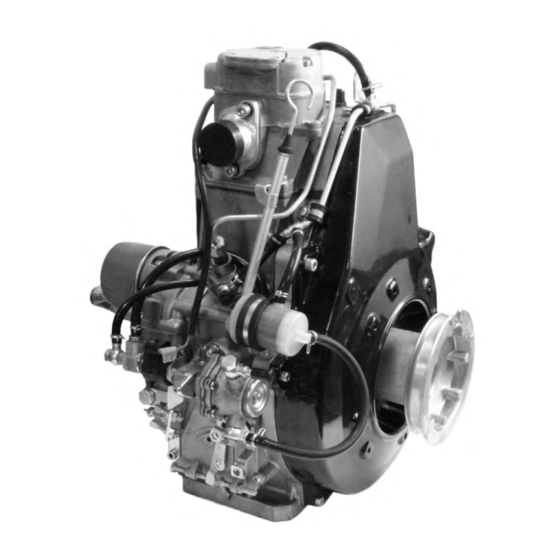
- Page 1 ERVICE ANUAL KD 441 ORIZONTAL RANKSHAFT cod. 1-5302-865 _ 2 ed._rev.01. 15 LD 441...
- Page 3 HLER. Information presented within this manual assumes the following: 1 - The person or people performing service work on KOHLER series engines is properly trained and equipped to safely and professionally perform the subject operation; 2 - The person or people performing service work on KOHLER series engines possesses adequate hand and KO- HLER special tools to safely and professionally perform the subject service operation;...
- Page 4 REGISTRATION OF MODIFICATIONS TO THE DOCUMENT Any modifications to this document must be registered by the drafting body, by completing the following table. Drafting Document Model Review Edition Revision Issue date Endorsed body code N° date CUSE/ATLO 1-5302-865 51203 2° 30-01-2009 28-05-2009 - 4 - Workshop Manual KD 441_cod. 1.5302.865_2 ed_ rev. 01.
-
Page 5: Table Of Contents
INDEX This manual contains pertinent information regarding the repair of KOHLER water-cooled, indirect injection Diesel engines type 20-04-2009 KD 441: updated TABLE OF CONTENTS GENERAL REMARKS AND SAFETY INFORMATION ....................8-9 General safety during operating phases ..........................9 Safety and environmental impact ............................9 Safety and warning decals .............................. - Page 6 Index Crankshaft, connection radius ............................39 Crankshaft, journal/crankpin diameter check, timing cover bearing internal diameters and crankshaft and big end bearing support ....................................39 Crankshaft, lubrication ducts, bore thread on flywheel side and p.t.o................39 Cylinder ..................................... 37 Cylinder head ..................................33 Cylinder roughness ................................37 Dimensions and clearance between guides and valve stems (mm) ................. 34 Dynamic balancer (on request) ............................
- Page 7 Index LUBRICATION SYSTEM ............................. 58-61 Internal strainer ................................. 59 Lubrication system ................................58 Oil pressure check ................................60 Oil pressure curve at full rotation speed ..........................60 Oil pressure curve at idle rotation speed .......................... 60 Oil pressure regulation valve ............................. 59 Oil pump ....................................
-
Page 8: General Remarks And Safety Information
− Only check belt tension when the engine is off. − Only use the eyebolts installed by KOHLER to move the engine. These lifting points are not suitable for the entire machine; in this case, the eyebolts installed by the manufacturer should be used. -
Page 9: General Safety During Operating Phases
− Variations to the functional parameters of the engine, adjustments to the fuel flow rate and rotation speed, removal of seals, demounting and refitting of parts not described in the operation and maintenance manual by unauthorized personnel shall relieve KOHLER from all and every liability for deriving accidents or for failure to comply with the laws in merit. − On starting, make sure that the engine is as horizontal as possible, unless the machine specifications differ. In the case of manual start-ups, make sure that the relative actions can take place without the risk of hitting walls or dangerous objects, also considering the movements made by the operator. -
Page 10: Technical Information
TECHNICAL INFORMATION TROUBLE SHOOTING THE ENGINE MUST BE STOPPED IMMEDIATELY WHEN: - The engine rpms suddenly increase and decrease; - A sudden and unusual noise is heard; - The colour of the exhaust fumes suddenly darkens; - The oil pressure indicator light turns on while running. TABLE OF LIKELY ANOMALIES AND THEIR SYMPTOMS The following table contains the possible causes of some failures which may occur during operation. -
Page 11: Manufacturer And Engine Identifications
Technical information MANUFACTURER AND ENGINE IDENTIFICATION Model R.P.M. Displacement (cc) Engine Serial Diesel KOHLER K version Customer code Month codification Production year (last two digits) Production month (alphabetically) January February March April June July August September October November December Workshop Manual KD 441_cod. 1.5302.865_2 ed_ rev. -
Page 12: Technical Data
Technical information TECHNICAL DATA ENGINE TYPE KD 441 Number of cylinders Bore Stroke Swept volume Compression ratio 20.5:1 R.P.M. 3600 N 80/1269/EEC-ISO 1585 Power kW (HP) NB ISO 3046 - 1 IFN 6.6(9.0) NA ISO 3046 - 1 ICXN 6.2(8.4) Max. -
Page 13: Overall Dimensions
Technical information OVERALL DIMENSIONS DIMENSIONS mm 135.8 42.4 159.5 165.5 235.5 135.5 172.2 85.5 Workshop Manual KD 441_cod. 1.5302.865_2 ed_ rev. 01. - 13 -... -
Page 14: Maintenance - Recommended Oil Type - Refilling
MAINTENANCE - RECOMMENDED OIL TYPE - REFILLING ROUTINE ENGINE MAINTENANCE Caution – Warning Failure to carry out the operations described in the table may lead to technical damage to the machine and/or system EXTRAORDINARY MAINTENANCE Interval Km OPERATION ITEM After the first 1000 km CHECK Check the valves gap Check the valves gap... -
Page 15: Acea Regualtions - Acea Sequences
Maintenance - Recommended oil type - Refilling LUBRICANT SAE Classification n the SAE classification, oils differ on the basis of their viscosity, and no other qualitative characteristic is taken into account. SAE 10W* The first number refers to the viscosity when the engine SAE 20W* is cold (symbol W = winter), while the second considers SAE 30*... -
Page 16: Engines Oil Capacity
Maintenance - Recommended oil type - Refilling PRESCRIBED LUBRICANT AGIP SUPERDIE- API CF- 4 specifications ACEA B2 - E2 MULTIGRADE MIL - L-46152 D/E 15W40 In the countries where AGIP products are not available, use oil API CF/SH for Diesel engines or oil corresponding to the military specification MIL-L-2104 C/46152 D. -
Page 17: Fuel Recommendations
Maintenance - Recommended oil type - Refilling FUEL RECOMMENDATIONS Purchase diesel fuel in small quantities and store in clean, approved containers. Clean fuel prevents the diesel fuel injectors and pumps from clogging. Do not overfill the fuel tank. Leave room for the fuel to expand. Immediately clean up any spillage during refueling. Never store diesel fuel in galvanized containers;... -
Page 18: Disassembly
- Before any intervention, the operator should lay out functional system. all equipment and tools in such a way as to enable him to carry out operations correctly and safely. Optimisation must be carried out beforehand at KOHLER - Before proceeding with operations, make sure that testing centres. -
Page 19: Rocker Arm Cover
Disassembly Hold the grip and firmly pull out the rope to start. Rocker arm cover Loosen fastening screws A and remove the rocker arm cover. Rocker arm cover breather system The crankcase breather system is located inside the rocker arm cover 1. Check that diaphragm 2 is intact ; wash with Diesel oil and blow through the small mesh element 4 with compressed air. -
Page 20: Fuelling/Injection Circuit
Disassembly Start pulley Loosen the 3 fastening screws and remove the pulley. When reassembling, tighten the screws to 23 Nm. Shroud Loosen the fastening screws and remove the conveyor. When refitting tighten shroud screws to 10 Nm. Fuelling/injection circuit Components: 1 Fuel filter return tube 2 Fuel filter Injection pump Injector pump exhaust pipe High pressure line... -
Page 21: Fuel Overflow System, Disassembly
Disassembly Fuel overflow system, Disassembly Loosen the outlet union of the injection pump and remove it. Loosen and remove the support screw of the main fuel overflow pipe. Remove the injector exhaust pipe from the main fuel overflow pipe. Disconnect the diesel fuel filter exhaust pipe and remove the whole fuel overflow pipe. Workshop Manual KD 441_cod. 1.5302.865_2 ed_ rev. 01. - 21 -... -
Page 22: Cylinder Head
Disassembly Loosen the inlet union of the injection pump. Loosen the outlet union of the injection pump. Loosen the fastening screw between the diesel fuel filter and the so- lenoid valve. Remove the fuel supply circuit complete with solenoid valve, filter and fuel pump. Injector Loosen screw A and remove the bracket fixing injector B to the cylin- der head. Remove injector C together with copper seal D. Important Caution - Warning The correct protrusion of the spray nozzle from the cylinder... -
Page 23: Connecting Rod
Disassembly Caution – Warning Do not demount when hot or the part could be deformed. Loosen the four nuts and remove the cylinder head. If the cylinder head surface is distorted, level it by removing up to 0.2 mm thickness. Always replace the seal, see fig. 130-131 on page 55 for the correct thickness. - Page 24 Disassembly Place the piston to the B.D.C.. Loosen the screws of the cap on the connecting rod big end. Rotate the crankshaft to T.D.C. position, until flywheel reference D is aligned with C on the crankcase. In T.D.C. position, the cylinder and the piston will be lifted as shown in the figure.
-
Page 25: Connecting Rod - Upward Replacement Of The Connecting Rod Half Bearings
Disassembly Remove the cap on the connecting rod big end using the unthreaded part of the special tool p/n 1460-340. Cylinder After removing the connecting rod cap, remove the cylinder, piston and connecting rod assembly from its seat. Remove the piston and the connecting rod from the cylinder by ma- nually pushing the piston downwards with respect to the cylinder. -
Page 26: Flywheel
Disassembly 9- Pull the bar outwards so as to place the connecting rod shaft on the crankshaft and make the upper connecting rod half bearing accessible. 10- Using the nylon bar, push on a half bearing side and disconnect it. 11- Using a magnet, remove the half bearing, taking care not to make it fall inside the engine. -
Page 27: Camshaft
Disassembly To remove the starter rim, it is advisable to cut it into several parts with a hacksaw and to then use a chisel. To replace, slowly heat for 15-20 minutes to a temperature of 300°C max. Fit the rim into the flywheel housing. make sure that it rests evenly against the support of the housing itself. -
Page 28: Crankshaft
Disassembly Equalizer shaft Rotate crankshaft B to remove equalizer shaft D. Crankshaft Remove the crankshaft. Speed governor gear Components: 1 Spool spacer 2 Spool 3 Weights 4 Spool guide 5 Gear 6 Oil pump driving shaft 7 Circlip 8 Thrust ring Remove drive rod 2 forcing the clamping teeth on rod collar 4 and the clearance shim 8. -
Page 29: Oil Pump
Disassembly Remove governor lock tension washer 7. Remove governor gear 5 taking care not to make drive pin 9 drop. Oil pump Components: 1 Cover 2 Oil pump driving shaft 3 Key 4 Pin 5 Internal rotor 6 External rotor Loosen the fastening screws and remove oil pump cover 1. - Page 30 Disassembly Remove oil pump drive shaft 2 with pin 3. Remove internal rotor 4. Remove outside rotor 5. For overhaul and oil pump checks, see page 59. - 30 - Workshop Manual KD 441_cod. 1.5302.865_2 ed_ rev. 01.
- Page 31 Notes ....................................................................................................................................................................................................................................................................................................................................................................................................................................................................................................................................................................................................................................................................................................................................................................................................................................................................................Workshop Manual KD 441_cod. 1.5302.865_2 ed_ rev. 01. - 31 -...
-
Page 32: Recommendations For Overhauls And Checking
OVERHAULS AND CHECKING RECOMMENDATIONS FOR OVERHAULS AND CHECKING – Information is given in a logical order in terms of timing and – Wash the components with special detergent and do not use sequence of operations. The methods have been selected, steam or hot water. -
Page 33: Valve, Springs
Overhauls and checking Cylinder head Valves - Disassembly Components: 1 Valve stem 2 Oil seal 3 Spring washer/set 4 Spring 5 Cap 6 Half collets Note: To remove half collets place a suitable plate under the valve head and press down firmly as indicated in the figure. Valve, springs Measure the free length with a caliper. -
Page 34: Dimensions And Clearance Between Guides And Valve Stems (Mm)
Overhauls and checking Valves, guides and housings Dimensions (mm) 1 Intake guide 2 Exhaust guide 11.000÷11.018 11.040÷11.055 Note: Valve guides with outer diameters increased by 0.5 mm are also available as spares. In this case, housing C must be in- creased by 0.5 mm for assembly purposes. -
Page 35: Valve Guides - Reassembly
Overhauls and checking Valve seats - Removal Important Place and clamp the cylinder head firmly onto the milling machi- Remove the valves, taking care the milling machine is aligned to the valve seats (see detail in the figure). Valve guides - Removal Important Firmly place the cylinder head under a press. Place tool A , p/n 1460-337, in the valve guide. -
Page 36: Overhauls And Checking
Overhauls and checking Valve seats - Reassembly Caution – Warning Thoroughly wash the cylinder head and the valve seats before reassembly. Place valve seat 1 onto its seat. Place the driving tool for valve seat C on the valve seat. Drive the seat in by hammering on tool C until the seat is inserted in its housing to its limit stop. -
Page 37: Cylinder
Overhauls and checking Injector protusion The end of nozzle A should protrude from the cylinder head plane : 3.00 ÷ 3.50 Adjust with copper gaskets B with thickness of 0.5, 1 and 1.5 mm Cylinder Set a bore gauge to zero with a calibrated ring. Check diameter at 1, 2 and 3;... -
Page 38: Connecting Rod, Piston Pin
Overhauls and checking Piston rings, play between the slots (mm) 0.11÷0.15 0.07÷0.11 0.03÷0.065 Replace the piston or piston rings if the value exceeds the maximum limit. Piston rings, assembly order A = 1st Nitrided plated piston ring B = 2nd piston ring (torsional) C = 3rd Nitrided plated piston ring (oil scraper) D = Chromium plated zone Note: If a word (top, or some other word) is written on the surface of... -
Page 39: Connecting Rod Alignement
Overhauls and checking Connecting rod alignement Use a dial gauge as shown in the figure. Check that axes are aligned using the piston pin; axial mis alignment A = 0.015; limit 0.03 mm. If the difference is greater, the connecting rod is not aligned, and it must be replaced with a new one. Crankshaft, lubrication ducts, bore thread on flywheel side and p.t.o. -
Page 40: Availability Of Bearings
Overhauls and checking Crankshaft - journal diameter (mm) The undersizes for the cran- kpin and main journal are 39.959÷39.975 oil seal working 0.25, 0.50 and 1 mm. area 41.984÷42.000 39.984÷40.000 39.984÷40.000 oil seal working 27.990÷27.977 area 291.500÷291.700 Crankshaft - Main bearing, big end, and crankshaft bearing inter- nal diameters, and relevant clearances. -
Page 41: Timing Cover Bearing - Reassembly
Overhauls and checking Timing cover bearing, crankshaft bearing, and thrust washer re- placement Legend 1 Thrust washer on timing cover side 2 Thrust washer on crankcase side 3 Bearing on timing cover side 4 Bearing on crankcase side. D Assembly/extraction tool for timing cover side bearing and for crankcase side bearing p/n 1460-333 Timing cover bearing - Extraction Important... -
Page 42: Crankcase Bearing - Extraction
Overhauls and checking Place bearing driving tool D on bearing 3. Operate the press and drive bearing 3 in until tool D touches thrust washer 1. Crankcase bearing - Extraction Important Place the crankcase firmly on a press, flywheel side facing up- wards. -
Page 43: Gearbox Extension, Bearing And Oil Seal Replacement
Overhauls and checking Oil seal ring on crankcase - Reassembly After lubricating the oil seal ring 2a (see detail), place it on the bea- ring making sure its internal channel (see figure on the side) is facing downwards. Operate the press and drive the oil seal ring in until tool J reaches its stop. -
Page 44: Oil Seal Ring - Reassembly
Overhauls and checking Once assembled, roller bearing 3 should be at the same level of the reference ridge on the gearbox extension. Oil seal ring - Reassembly Caution – Warning Lubricate the oil seal ring before reassembly. Place oil seal ring 2 on the gearbox extension opening making sure the channel is facing upwards (see figure on the side). -
Page 45: Camshaft Journals And Bore
Overhauls and checking Camshaft journals and bore Use an inside dial gauge to measure the camshaft pin housing dia- meters. Camshaft, pin and housing dimensions, and relevant clearances (mm) 17.966÷17.984 15.957÷15.984 16.000÷16.018 18.00÷18.018 (D-A) 0.016÷0.052 (D-A) Limit 0.100 (C-B) 0.016÷0.061 (C-B) 0.120 Limit... -
Page 46: Valve Timing - Angles
Overhauls and checking Valve timing - Angles Angle values are measured by turning the crankshaft clockwise. S = Piston at top dead centre I = Piston at bottom dead centre α = Intake valve opening β = Intake valve closing γ... - Page 47 Notes ....................................................................................................................................................................................................................................................................................................................................................................................................................................................................................................................................................................................................................................................................................................................................................................................................................................................................................Workshop Manual KD 441_cod. 1.5302.865_2 ed_ rev. 01. - 47 -...
-
Page 48: Piston
REASSEMBLY RECOMMENDATIONS FOR REASSEMBLING – Information is given in a logical order in terms of timing and – Before any intervention, the operator should lay out all equi- sequence of operations. pment and tools in such a way as to enable him to carry out The methods have been selected, tested and approved by operations correctly and safely. -
Page 49: Connecting Rod Big End Cap
Reassembly Rings Important Generously lubricate the rings. Offset the ring tips by 120°. Use compression pliers to insert the piston into the cylinder. Cylinder After lubricating the connecting rod big end bearing, insert the cylin- der, piston and connecting rod assembly from its seat into the cran- kcase, taking care the cylinder keeps its correct position, as shown in figure 106. -
Page 50: Connecting Rod, Tightening
Reassembly Connecting rod, tightening Insert the connecting rod cap screws without tightening too firmly. Tighten the connecting rod cap screws alternately by using a torque wrench until they have been tightened to the specified torque of 35 Valve tappets Insert the tappets after lubricating them in their seat in the crankcase. Injection pump and tappet fitting in the crankcase Fit tappets 3 so that screw 6 is introduced into guide 4. -
Page 51: Equalizer Shaft
Reassembly Camshaft Caution – Warning Lubricate the camshaft bearing on the crankcase. Match the reference tip on crankshaft gear A with the 2 ones on camshaft gear B (see circled area 1). Insert the camshaft. Equalizer shaft Caution – Warning Lubricate the equalizer shaft support bearing. -
Page 52: Speed Governor Gear
Reassembly Insert internal rotor 4 with pin seat 3 facing the assembler. Insert oil pump drive shaft 2 together with pin 3, which should be in- serted in its seat on internal rotor 4. Assemble oil pump cover 1 and tighten the screws alternately to 10 Speed governor gear Components: 1 Spool spacer... -
Page 53: Gear Cover On Timing Side
Reassembly Assemble governor gear 5 by inserting drive pin 9 into its seat on the gear. Assemble governor lock tension washer 7. Insert drive rod 2 with clearance shim 8 forcing the clamping teeth on drive collar 4. Gear cover on timing side Proper sealing between gear cover and crankcase is ensured by the liquid sealant "Loctite 5205". Carefully clean the two sealing surfaces and spread the sealant uniformly. -
Page 54: Camshaft End Play
Reassembly Camshaft end play Temporarily fit camshaft 1 complete with washer; tighten gear cover 2 to 25 Nm. Check end play by moving the camshaft back and forth using a sui- table tool; the end play value is 0.10÷0.25 mm and is not adjustable. In case of excessive clearance, replace the camshaft and the timing cover. -
Page 55: Assessing Head Gasket Thickness
Reassembly Oil seals, crankshaft - Replacement It is possible to replace the oil seal rings if the crankshaft is assem- bled by following the instructions below. Caution – Warning A warped oil seals may allow the introduction of air into the engine thus causing crankcase ventilation problems. -
Page 56: Flywheel
Reassembly Having chosen the required thickness, mount the gasket as shown in the figure. Together with the head gasket, assemble the pushrod gasket. Head tightening Caution – Warning Lubricate the nuts and the washers with engine oil. Follow the order shown in the figure to tighten the 4 nuts M9 at diffe- rent stages with a torque wrench. phase: tighten all nuts cross way to 5 Nm phase: tighten all nuts in the same order to 20Nm phase: tighten all nuts in the same order to 30Nm... -
Page 57: Injector
Reassembly Valve/rocker arm clearance Caution – Warning Adjust the valve/rocker arm clearance when the engine is cold. Turn the engine clockwise and place the piston at the TDC. Loosen lock nut A while locking lock nut B in its position, as shown in the figure. -
Page 58: Lubrication System
LUBRICATION SYSTEM Danger – Attention The engine can be damaged if allowed to operate with insufficient oil. It is also dangerous to add too much oil because its combu- stion may lead to a sharp increase in the rotation speed. Use suitable oil in order to protect the engine. Nothing more than lubrication oil can influence the performances and life of an engine. Use of an inferior quality oil or failure to regularly change the oil will increase the risk of piston seizure, will cause the piston rings to jam and will lead to rapid wear on the cylinder liner, the bearings and all other moving parts. -
Page 59: Internal Strainer
Lubrication system Oil pump Components: 1 Cover 2 Shaft 3 Key 4 Pin 5 Internal rotor 6 External rotor Oil pump delivery at 3000 rpm is 5.8 l/min. Oil pump - Clearance between rotors Measure clearance as shown in the figure; the max. value is 0.13 mm;... -
Page 60: Oil Pressure Check
Lubrication system Oil pressure check Connect a 10 bar pressure gauge to the oil filter fitting. Start the engine and check pressure as a function of the oil tempera- ture (see below). Oil pressure curve at idle rotation speed The curve is obtained with engine running at a constant speed of 1200 r.p.m. - Page 61 Notes ................................................................................................................................................................................................................................................................................................................................................................................................................................................................................................................................................................................................................................................................................................................................................................................................................................................................................................................................................Workshop Manual KD 441_cod. 1.5302.865_2 ed_ rev. 01. - 61 -...
-
Page 62: Fuel Lift Pump
FUEL SYSTEM Fuelling/injection circuit Components: 1 Fuel filter return tube 2 Fuel filter Injection pump Injector pump exhaust pipe High pressure line Fuel lift pump Fuel pump suction (to be connected to the tank) Fuel feeding tubes Solenoid valve 10 Injector 11 High pressure line 12 Injector leak-off line 13 Fuel overflow pipe (to be connected to the tank) Fuel filter... -
Page 63: Fuel Lift Pump - Filter Cleaning
Fuel system Fuel pump, drive rod protrusion Components: 1 Fuel pump 2 Crankcase 3 Drive rod 4 Eccentric Check while eccentric 4 is at rest (lowest point of travel). Protrusion A of drive rod 3 is 1.5÷1.9 mm; it is not adjustable. Replace the drive rod if it does not comply with tolerance. -
Page 64: Injection Pump
Fuel system Solenoid valve Dimensions (mm) Characteristics: 12 V 0.9 A. Injection pump This is of the simplified QLC type; it is housed in the crankcase and is controlled by the camshaft via tappets. Injection pump fitting in the crankcase Fit pad 2 into the tappet so that recess B points downwards as shown in the figure. -
Page 65: Injection Pump Components And Disassembly
Fuel system Injection pump components and disassembly 1 Delivery union 2 Filler 3 Spring 4 Gasket 5 Delivery valve 6 Gasket 7 Spring retainer 8 Spring 9 Sleeve 10 Rack 11 Piston (pumping element) 12 Pin Fuel exhaust union screw with non-return valve Fuel inlet union screw Fastening Plunger barrel (in the injection pump case) -
Page 66: Static Injection Timing
Fuel system Injection pump non-return valve In the exhaust union screw there is a non-return valve. The purpose of this valve is to improve the injection phase by expelling the air in the fuel and preventing it from being sucked in by the pump during the in- take phase. - Page 67 Fuel system References on the flywheel A = Reference of fixed TDC on crankcase B = Injection lead reference on the flywheel C = TDC reference on flywheel α = Reference in degrees between B and C. Injection advance specified value Conversion table from millimetres into degrees α A/C mm A/C mm α 13.61 Motor type with external Ø flywheel 15.87 18.14 20.41...
-
Page 68: Injector
Fuel system Injector Components: 1 Body 2 Union 3 Adjusting shim 4 Spring 5 Pressure rod 6 Pin 7 Nozzle 8 Nozzle cup 9 Needle valve 10 Tip 11 Duct 12 Return hole After re-assembly, tighten ring nut 8 to a 50 Nm torque value. Bar filter Bar filter A is a filter inside the injector inlet union. -
Page 69: Injector Calibration
Fuel system Fuel system Nozzles The set-up between the needle and the guide must leave the needle free to fall and merely as a result of its own weight, when lifted 7mm from its seat and rotated in different directions, with the nozzle kept at a 45°... -
Page 70: V, 17A Electric Ignition Diagram
ELECTRICAL SYSTEM 12V, 17A electric ignition diagram Components: 1 Alternator 2 Starter motor 3 Voltage regulator 4 Battery 5 Oil pressure switch 6 Oil pressure light 7 Key switch 8 Battery charging light 9 Capacity bank 10 Push button switch Note: The battery, which is not supplied, should have 12V nominal voltage rating and a capacity of not less than 44 Ah / 210 Amp. -
Page 71: Connection Diagram
Electrical system Voltage regulator 14.5V, 20A: for 12V, 17A alternators with 2 output wires The tabs are in different sizes to prevent incorrect connections. Caution – Warning When the engine is running do not disconnect battery cables or switch key to "off" position. Do not place the governor near heat sources , but in well ventila- ted areas above 75°C. -
Page 72: Testing Voltage Regulator For Proper Operation
Electrical system Testing voltage regulator for proper operation Check that connections correspond to the schematic. Disconnect the terminal from the battery positive pole. Connect a d.c. voltmeter between the battery poles. Fit an ammeter between the positive pole and the B+ on voltage regu- lator. -
Page 73: Characteristic Curves For Starting Motor Type Bosch Dw (L) 12V, 1.2 Kw
Electrical system Starting motor - BOSCH Anti-clockwise rotation direction (viewed from pinion side) A = 17.5÷19.5 mm Distance from flywheel rim surface to starter motor flange surface. Note: Contact Bosch service centers for repair operations. Characteristic curves for starting motor type BOSCH DW (L) 12V, 1.2 KW The curves were obtained at a temperature of -20°C with 66 Ah battery. U = Motor terminal voltage in Volts n = Motor speed in r.p.m. -
Page 74: Adjustments
ADJUSTMENTS Accelerator lever for speed governor with min/max speed system A Internal governor lever into control group B Nut C Internal accelerator lever into control group D Lock ring E Max. speed spring F Min. speed spring Assembly procedure for accelerator lever of speed governor with min/max speed system Insert the pin in the hole on the internal accelerator lever. -
Page 75: Setting The Fast Idle (Standard) Rotation Speed
Adjustments With a special tool matr.1460-342, mount the nut on the threaded pin Keeping lever C displaced, close the hole with plug A and gasket B. Setting the slow idle (standard) rotation speed After having filled the engine with oil and fuel, start it and allow it to warm up for 10 minutes. -
Page 76: Injection Pump Delivery Approximate Setting
Adjustments Fasten lock nut 4 keeping adjusting screw 3 in its position. Injection pump delivery limiting and torque adapter Delivery limiting device C has the function of limiting the injection pump max. delivery. The same mechanism acts also as a torque gearing device. Indeed, under torque, spring E inside the limiter is compressed when subject to the action of the governor levers, by exploiting the opposed forces of the accelerator spring and of the centrifugal weights of the speed governor. -
Page 77: Injection Pump Delivery Setting For Engines With Dynamometric Brake
Adjustments Injection pump delivery setting for engines with dynamometric brake 1 - Start engine to idling speed 2 - Unscrew delivery limiting device C ( see fig.187) 3 - Accelerate the engine and load the dynamometric brake until obtaining power at the rpm required by the application manufacturer. -
Page 78: Storage
STORAGE ENGINE STORAGE - When the engines are not in use for more than 6 months, they have to be protected performing the operations descri- bed in the following pages. If the engine is not to be used for extensive periods, check the storage area conditions and the type of packaging and make sure that these are suitable for correct storage. -
Page 79: Preparing The Engine For Operation After Protective Treatment
Storage PREPARING THE ENGINE FOR OPERATION AFTER PROTECTIVE TREATMENT After the storage period and before starting up the engine and preparing it for operation, you need to perform certain operations to ensure maximal efficiency conditions. 1 - Remove the protective sheet. 2 - Remove any sealing devices from the exhaust and intake ducts. 3 - Use a cloth soaked in degreasing product to remove the protective treatment from the external parts. -
Page 80: Use Of Sealant
MAIN TORQUE SPECIFICATIONS AND USE OF SEALANTS MAIN TORQUE SPECIFICATIONS Diam. and pitch POSITION Torque ( Nm ) ( mm ) Re-coil starting Connecting rod Rocker arm adjusting screw lock nut 6x0.5 Rocker arm adjusting screw pin 8x1.25 Shroud Rocker arm cover Control arm cover Bottom cap Exhaust manifold... - Page 81 Main torque specifications and use of sealants Table of tightening torques for standard screws (coarse thread) Resistance class (R) 10.9 12.9 Quality/ Dimensions R>400N/mm R>500N/mm R>600N/mm R>800N/mm R>1000N/mm R>1200N/mm Diameter 1000 1200 1050 1500 1800 1088 1450 2000 2400 Table of tightening torques for standard screws (fine thread) Resistance class (R) 10.9 12.9...
-
Page 82: Special Tools
SPECIAL TOOLS SPECIAL TOOLS DESCRIPTION Part N°. Gasket selection tool 1460-343 Timing tool 1460-344 Flywheel puller 1460-120 Flywheel clamping tool 1460-330 Bancer shaft bearing pressing tool 1460-327 Bancer shaft bearing extractor tool 1460-345 Oil seal pressing tool flywheel side 1460-328 Oil seal pressing tool PTO side 1460-346 Roller bearing assembly/disassembly and 1460-347... -
Page 83: Special Tools
Special tools SPECIAL TOOLS DESCRIPTION Part N°. Oil seal protection tool flywheel side 1460-331 Fuel pipe assembly tool 1460-023 Assembly/extraction tool for timing cover 1460-333 side bearing and for crankcase side bearing Tool for valve stem O-ring assembly 1460 - 047 Tool for valve cotters assembly/disassembly 1460 - 113 Valve guide removal tool 1460-337... - Page 84 FORM NO.: 1-5302-865 ISSUED: 30/01/2009 REVISED: 28/05/2009 REV.01 LOMBARDINI INDIA P.L. Plot No. J-2/1 MIDC Industrial Area - Chikaltana - (AURANGABAD) – 431210 Maharashtra - INDIA Tel. (+91) 240 2471415 Fax. (+91) 0240 2486234 E-MAIL: marketing@lombardini.it...
Need help?
Do you have a question about the RD 441 and is the answer not in the manual?
Questions and answers