Table of Contents
Advertisement
Quick Links
Advertisement
Table of Contents

Subscribe to Our Youtube Channel
Related Manuals for LevelOne MSL-3S79


Summary of Contents for LevelOne MSL-3S79
- Page 1 MSL-3S79 3-Slot Gigabit Modular L2 Managed Switch User Manual V1.0...
- Page 2 FCC Warning This Equipment has been tested and found to comply with the limits for a Class-A digital device, pursuant to Part 15 of the FCC rules. These limits are designed to provide reasonable protection against harmful interference in a residential installation. This equipment generates uses and can radiate radio frequency energy and, if not installed and used in accordance with the instructions, may cause harmful interference to radio communications.
-
Page 3: Table Of Contents
Content 0 B C hapter 1 Introduction ....................1 8 B 1 .1 Hardware Features ....................2 9 B 1 .2 Software Feature ....................4 1 0 B 1 .3 Package Contents ....................6 1 B C hapter 2 Hardware Description ..................8 1 1 B 2 .1 Physical Dimension .................... - Page 4 7 9 B 6 .4.5.3 TFTP Restore Configuration ............. 23 5 6 B 6 .4.6 System Event Log ..................23 8 0 B 6 .4.6.1 LOG Configuration ................23 8 1 B 6 .4.6.2 Logging Events Level ............... 25 8 2 B 6 .4.6.3 Logging RAM Table ................26 8 3 B 6 .4.6.4 Logging Flash Table .................
- Page 5 9 7 B 6 .6.6.2 IGMP Static Configuration ..............46 7 0 B 6 .6.7 LLDP......................47 9 8 B 6 .6.7.1 LLDP Configuration ................47 9 9 B 6 .6.7.2 LLDP Neighbor Table ............... 48 2 8 B 6 .7 Security ......................... 48 7 1 B 6 .7.1 802.1x/ RADIAS ..................
- Page 6 4 6 B D HCP Server Commands Set ..................77 4 7 B S ecurity IP Commands Set ..................78 4 8 B 8 02.1X Commands Set ....................78 4 9 B L LDP Commands Set ....................79 5 0 B A CL Commands Set ....................80...
-
Page 7: C Hapter 1 Introduction
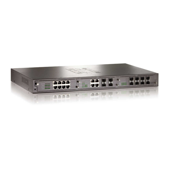
C hapter 1 Introduction The MSL-3S79 is a modular switch that can be used to build high-performance switched workgroup networks. This switch is a store-and-forward device that offers low latency for high-speed networking. The Switch is targeted at workgroup, department or backbone computing environment. -
Page 8: .1 Hardware Features
1 .1 Hardware Features IEEE 802.3 10BASE-T IEEE 802.3u 100BASE-TX IEEE 802.3z Gigabit fiber IEEE 802.3ab 1000Base-T IEEE 802.3x Flow control and Back pressure IEEE 802.3ad Port trunk with LACP Standards IEEE 802.1d Spanning tree protocol IEEE 802.1w Rapid spanning tree IEEE 802.1p Class of service IEEE 802.1q VLAN Tagging IEEE 802.1x User authentication... - Page 9 48Gbps. Packet buffer 6Mbits Dimensions 440mm(W) x 280mm(D) x 44mm(H) MAC Address -40℃~70℃, 5%~95%RH Storage Temp. 0℃~45℃, 5%~95%RH Operational Temp. AC 100~240V 50/60Hz, Power Supply Redundant Power: DC 12~48V Power 35 Watts Consumption Ventilation 2 fan at the rear Compliance with FCC Class A, CE Safety Compliance with UL, cUL, CE/EN60950-1...
-
Page 10: .2 Software Feature
1 .2 Software Feature Management SNMP v1/v2c, Telnet, RMON1, CLI and Web management. RFC 2863 Interface Group MIB, RFC 1213 MIBII, RFC 1493 Bridge MIB, RFC 2674 VLAN MIB, RFC 1643 Ethernet Like MIB, RFC 1215 Trap MIB, RFC 1757 RMON MIB, Private MIB Cold start/Warm start trap, SNMP Trap... - Page 11 Port based VLAN, up to 24 groups IEEE802.1Q Tag VLAN Static VLAN groups up to 256 entries and dynamic VLAN VLAN groups up to 2048, the VLAN ID can be assigned from 1 to 4094. GVRP Per port 8 priority queues and support strict and WRR priority rule.
-
Page 12: 0 B 1 .3 Package Contents
Packet filter Broadcast storm control LLDP Support IEEE 802.1ab Link Layer Discovery Protocol 1 .3 Package Contents 1 0 B Unpack the contents of the and verify them against the checklist MSL-3S79 below. One MSL-3S79 Four Rubber Feet... - Page 13 Power Cord Rack-mounted kit RS-232 Cable CD Manual Compare the contents of your MSL-3S79 package with the standard checklist above. IF any item is missing or damaged, please contact your local dealer for service.
-
Page 14: C Hapter 2 Hardware Description
This section mainly describes the hardware of the MSL-3S79. 2 .1 Physical Dimension 1 1 B The physical dimensions of the MSL-3S79 is 440mm(W) x 280mm(D) x 44mm(H) 2 .2 LED Indicators 1 2 B The LED Indicators gives real-time information of systematic operation status. The LED indicators are located in every module. - Page 15 Green Ethernet Link connected LK/ACT Blink The port is receiving or transmitting data. No device attached or Link is disconnected 4-port 1000Base-T + 4-port Mini GBIC module Meaning L ED S tatus 1 0 8 B 1 0 9 B Gigabit Copper Green Link on 1000Mbps mode...
-
Page 16: 3 B 2 .3 Rear Panel
2 .3 Rear Panel 1 3 B The 3-pronged power plug is located at the Rear Panel of the MSL-3S79 as shown in figure. The Switches will work with AC in the range 100-240V AC, 50-60Hz. The DC redundant power jack is optional. -
Page 17: C Hapter 3 Hardware Installation
C hapter 3 Hardware Installation 3 .1 Desktop Installation 1 4 B Set the switch on a sufficiently large flat space with a power outlet nearby. The surface where you put your Switch should be clean, smooth, level, and sturdy. Make sure there is enough clearance around the Switch to allow attachment of cables, power cord and air circulation. -
Page 18: 6 B 3 .3 Power On
3 .3 Power On 1 6 B Connect the power cord to the power socket at the rear panel of the Switch. The other side of power cord connects to the power outlet. The internal power can work with AC in the voltage range of 100-240VAC/ frequency 50~60Hz or 12-48VDC (It’s optional). -
Page 19: C Hapter 4 Network Application
This section provides you a few samples of network topology in which the switch is used. In general, the MSL-3S79 is designed as a segment switch. That is, with its large address table (16K MAC address) and high performance, it is ideal for interconnecting networking segments. - Page 20 You can use any of the RJ-45 port of the MSL-3S79 to connect with another Switch or Hub to interconnect each of your small-switched workgroups to form a larger switched network.
-
Page 21: C Hapter 5 Console Management
C hapter 5 Console Management 5 .1 Connecting to the Console Port 1 9 B The Console port is a female DB-9 connector that enables a connection to a PC or terminal for monitoring and configuring the Switch. Use the supplied RS-232 cable with a male DB-9 connector to connect a terminal or PC to the Console port. -
Page 22: 1 B 5 .3 Cli Management
The settings of communication parameters After finishing the parameter settings, click “OK“. When the blank screen shows up, press Enter key to get into command line mode. Please see below figure for login screen. 5 .3 CLI Management 2 1 B The system supports console management (CLI command). -
Page 23: C Hapter 6 Web-Based Management
C hapter 6 Web-Based Management This section introduces the configuration and functions of the Web-Based management. 6 .1 About Web-based Management 2 2 B On CPU board of the switch there is an embedded HTML web site residing in flash memory, which offers advanced management features and allow users to manage the switch from anywhere on the network through a standard browser such as Microsoft Internet Explorer. -
Page 24: 4 B 6 .3 System Login
6 .3 System Login 2 4 B Launch the Internet Explorer on the PC Key in “http:// “+” the IP address of the switch”, and then Press “Enter”. The login screen will appear right after Key in the user name and password. The default user name and password are the same as “admin”... -
Page 25: 2 B 6 .4.2 Switch Information
System information interface 6.4.2 Switch Information 5 2 B 6.4.2.1 Main Board 7 5 B Hardware Version: display the hardware version Fan 1 Status: display the status of Fan 1 Fan 2 Status: display the status of Fan 2 6.4.2.2 Management Software 7 6 B Firmware Version: display the firmware version Configure Data version: display the configure data version... -
Page 26: 3 B 6 .4.3 Ip Configuration
6.4.3 IP Configuration 5 3 B User can configure the IP Settings. IP Address Mode: Static: It means the IP address of this switch will be assigned by user. DHCP: It means the IP address of this switch will be assigned by the network DHCP server. - Page 27 switch system will be a DHCP server. DHCP Server Settings DHCP Server: Enable or disable the DHCP Server function. Enable – the switch will be a DHCP server on your local network. DHCP IP Address Pool: User has to set a range of IP addresses for the DHCP server assigning an IP address to the DHCP client by giving the starting IP address and how many IP addresses within this address pool.
-
Page 28: 5 B 6 .4.5 Firmware Update
DHCP Server Configuration interface DHCP Client Information Display the DHCP Client information which has gotten an IP address from the DHCP server. 6.4.5 Firmware Update 5 5 B 6.4.5.1 TFTP Download Firmware 7 7 B It provides the functions to allow a user to update the switch firmware. Before updating, make sure you have your TFTP server ready and the firmware image is on the TFTP server. -
Page 29: 9 B 6 .4.5.3 Tftp Restore Configuration
TFTP-Configuration Backup interface 6.4.5.3 TFTP Restore Configuration 7 9 B User can restore EEPROM value from TFTP server, but user must put back the backup file in TFTP server, switch will download it back. TFTP Server IP Address: Fill in the TFTP server IP. Restore File Name: Fill in the correct restore file name. - Page 30 Remote Logging: Mark this check box for enabling to set Facility Level, Trap Level, Log Server IP 1, and Log Server IP 2. Facility Level: Set the level range of 16 to 23. Trap Level: Set the level range of 0 to 7. Log Server IP 1: Assign a remote log server IP address.
-
Page 31: 1 B 6 .4.6.2 Logging Events Level
LOG Configuration interface 6.4.6.2 Logging Events Level 8 1 B User can select the system log events and SMTP events. When selected events occur, the system will send out the log information. The range of Logging Event Level is from level 0 to level 7. -
Page 32: 2 B 6 .4.6.3 Logging Ram Table
Remote Logging, and SMTP Logging, the system will issue a log record to location where user has designated. After configuring, click Apply Logging Event Level: 4 events – Cold Start Event, Warm Start Event, Auth Failure Event, and Port Link Change Event. Pull down the right side item menu to select the event level. -
Page 33: 3 B 6 .4.6.4 Logging Flash Table
Logging RAM Table interface. 6.4.6.4 Logging Flash Table 8 3 B Logging Flash Table displays the logs which have been sent to Flash ROM. Logging ROM Table interface 6.4.7 Security Manager 5 7 B Change login user name and password for the management security issue User Name: Key in the new user name (The default is “admin”) New Password: Key in the new password (The default is “admin”) Confirm Password: Re-type the new password... -
Page 34: 6 B 6 .5 Port
6 .5 Port 2 6 B 6.5.1 Port Statistics 5 8 B Display the port statistic information. Port Statistic interface 6.5.2 Port Information 5 9 B The following information provides the current port statistic information... -
Page 35: 0 B 6 .5.3 Port Control
Port Information interface 6.5.3 Port Control 6 0 B In Port configuration, user can view every port status that depended on user setting and the negotiation result. Port: select the port that user wants to configure. State: Current port status. The port can be set to disable or enable mode. If the port setting is disabled, it will not receive or transmit any packet. -
Page 36: 1 B 6 .5.4 Port Trunk
Port Configuration interface 6.5.4 Port Trunk 6 1 B The Link Aggregation Control Protocol (LACP) provides a standardized means for exchanging information between Partner Systems on a link to allow their Link Aggregation Control instances to reach agreement on the identity of the Link Aggregation Group to which the link belongs, move the link to that Link Aggregation Group, and enable its transmission and reception functions in an orderly manner. -
Page 37: 5 B 6 .5.4.2 Trunk Information
Click Remove button to remove the port from a trunk group To delete Trunk Group, select the Group Id and click Delete button. Trunk Configuration interface 6.5.4.2 Trunk Information 8 5 B After setting up the trunk group, user will see the related information as below. Trunk Information interface 6.5.4.3 Port Activity 8 6 B... -
Page 38: 2 B 6 .5.5 Port Mirror
Port Activity interface 6.5.5 Port Mirror 6 2 B The port mirror is a method for monitor traffic in switched networks. Traffic through ports can be monitored by specific port. That means traffic goes in or out monitored ports will be duplicated into analysis port. - Page 39 Port Mirror Configuration interface Port Mirroring State: enable or disable the port mirror function Analysis Port: Select a port for analyzing all monitor port traffic. User can connect mirror port to LAN analyzer or Netxray. Monitor Port: The ports which user wants to monitor. All monitored port traffic will be copied to analysis port.
-
Page 40: 3 B 6 .5.6 Rate Limiting
Click Apply 6.5.6 Rate Limiting 6 3 B User can set up the bandwidth rate and packet limitation type of each port. Input State: There are 4 check boxes of Bc, Mc, UnkUc, KnownUc for selecting. Rate (1~1526)(Rate*655Kbps): Type in the input rate limit in number between 1~1526. -
Page 41: 7 B 6 .6.1.1 Vlan Mode Configuration
physically. 6.6.1.1 VLAN Mode Configuration 8 7 B The switch supports port-based and 802.1Q (tagged-based) VLAN. The default configuration of VLAN operation mode is “802.1Q”. VLAN Mode Configuration interface 6.6.1.2 Port VLAN Id Configuration 8 8 B Port: Select the port number in the table list. VLAN ID: Key in the VLAN ID. -
Page 42: 9 B 6 .6.1.3 Vlan Entry
6.6.1.3 VLAN Entry 8 9 B Edit the existing VLAN Group. Select the VLAN group in the table list. Click Edit VLAN Table Configuration interface User can add/ remove the ports from a VLAN group. Click Next VLAN Table Configuration - Edit interface Mark the check box to tag the ports of a VLAN group. -
Page 43: 5 B 6 .6.2 Rapid Spanning Tree
Click Apply VLAN Table Configuration - Edit interface 6.6.2 Rapid Spanning Tree 6 5 B The Rapid Spanning Tree Protocol (RSTP) is an evolution of the Spanning Tree Protocol and provides for faster spanning tree convergence after a topology change. The system also supports STP and the system will auto detect the connected device that is running STP or RSTP protocol. - Page 44 Spanning-tree Protocol configuration messages before attempting a reconfiguration. Enter a value between 6 through 40 Hello Time (1-10): the time that controls switch sends out the BPDU packet to check RSTP current status. Enter a value between 1 through 10 Forward Delay Time (4-30): the number of seconds a port waits before changing from its Rapid Spanning-Tree Protocol learning and listening states to the forwarding state.
-
Page 45: 1 B 6 .6.2.2 Stp Port Configuration
6.6.2.2 STP Port Configuration 9 1 B User can configure path cost and priority of every port. 1. Select the port in Port column. 1. Priority: Decide which port should be blocked by priority in LAN. Enter a number 0 through 240. -
Page 46: 6 B 6 .6.3 Snmp
RSTP Port Configuration interface 6.6.3 SNMP 6 6 B Simple Network Management Protocol (SNMP) is the protocol developed to manage nodes (servers, workstations, routers, switches and hubs etc.) on an IP network. SNMP enables network administrators to manage network performance, find and solve network problems, and plan for network growth. -
Page 47: 7 B 6 .6.4 Qos
SNMP Trap managers A trap manager is a management station that receives traps, the system alerts generated by the switch. If no trap manager is defined, no traps will issue. Create a trap manager by entering the IP address of the station and a community string. To define management stations as trap manager and enter SNMP community strings and selects the SNMP version. -
Page 48: 2 B 6 .6.4.1 Qos Configuration
6.6.4.1 QoS Configuration 9 2 B Queue Profile: Select the queue profile from the column list. Priority Precedence: There are 4 priority precedence selections available. Click Adpply QoS Configuration interface 6.6.4.2 Port-bace Configuration 9 3 B Port: Select the number port from the column list. Default Port Priority (0-7): Assign the priority level. -
Page 49: 4 B 6 .6.4.3 Cos Configuration
6.6.4.3 COS Configuration 9 4 B Set up the COS priority level. COS priority: Set up the COS priority level 0~7, 7 is the highest priority. Click Apply COS Configuration interface 6.6.4.4 DSCP Configuration 9 5 B Set up the DSCP priority. Mapping DSCP priority: The system provides 0~63 DSCP priority level. -
Page 50: 8 B 6 .6.5 Sntp
DSCP Configuration interface 6.6.5 SNTP 6 8 B User can configure the SNTP (Simple Network Time Protocol) settings. The SNTP allows user to synchronize switch clocks in the Internet. SNTP Server Link Status: Display the link status of SNTP server. Switch Current Time: Display the current time of the switch. -
Page 51: 9 B 6 .6.6 Igmp
SNTP Configuration interface 6.6.6 IGMP 6 9 B The Internet Group Management Protocol (IGMP) is an internal protocol of the Internet Protocol (IP) suite. IP manages multicast traffic by using switches, routers, and hosts that support IGMP. Enabling IGMP allows the ports to detect IGMP queries and report packets and manage IP multicast traffic through the switch. -
Page 52: 7 B 6 .6.6.2 Igmp Static Configuration
information. IP multicast addresses range from 224.0.0.0 through 239.255.255.255. IGMP Snoop: Enable or disable the IGMP snoop. IGMP Query: The IGMP query function has 3 modes - Enable, Disable or Auto - for selection. The IGMP query information will be displayed in IGMP status section. -
Page 53: 0 B 6 .6.7 Lldp
Port ID: Select the port number in the specific multicast group IP address. VLAN ID: Input the value of VLAN ID. IP Address: Assign a multicast group IP address in the range of 224.0.0.0 ~ 239.255.255.255. Click "Add". If you want to delete an entry from table, select the entry and click "Delete". IGMP Static Configuration interface 6.6.7 LLDP 7 0 B... -
Page 54: 9 B 6 .6.7.2 Lldp Neighbor Table
LLDP Configuration interface 6.6.7.2 LLDP Neighbor Table 9 9 B User will see all information of port by LLDP enable. LLDP Neighbor Table interface 6 .7 Security 2 8 B 6.7.1 802.1x/ RADIAS 7 1 B 802.1x is an IEEE authentication specification that allows a client to connect to a wireless access point or wired switch but prevents the client from gaining access to the port until it provides authority, like a user name and password that are verified by a separate server. - Page 55 Supplicant Timeout: Set the period of time the switch waits for a supplicant response to an EAP request. Server Timeout: Set the period of time the switch waits for a server response to an authentication request. ReAuthMax: Set the number of authentication that must time-out before authentication fails and the authentication session ends.
-
Page 56: 0 1 B 6 .7.1.2 Port Configuration
6.7.1.2 Port Configuration 1 0 1 B Port Configuration interface You can configure 802.1x authentication state for each port. The State provides Disable, Authorize, Accept and Reject. Disable: This function is disabled. Authorize: The specified port is set to the Authorized or Unauthorized state in accordance with the outcome of an authentication exchange between the supplicant and the authenticator. -
Page 57: 2 B 6 .7.2 Port Security
specified Radius Server. Shared Key: Set an encryption key for using during authentication sessions with the specified radius server. This key must match the encryption key used on the Radius Server. NAS Identifier: A string used to identify this switch. Click Apply 6.7.2 Port Security... -
Page 58: 0 4 B 6 .7.2.2 Filter Mac Address Table
User can add static MAC address in switch MAC table. MAC Address Port VLAN ID: list the MAC Address Port. VLAN ID MAC Address: Specify the destination MAC address to add to the address table. Port.No: pull down the selection menu to select the port number. Vid: enter the Vid of the MAC address, it has to be between 1 to 4094. -
Page 59: 0 5 B 6 .7.2.3 Mac Address Table Aging
If user wants to delete the MAC address from filtering table, select the MAC address and click Delete 6.7.2.3 MAC Address Table Aging 1 0 5 B Aging Status: Pull-down menu to enable MAC address table aging function. Aging Time (20~620): Assign the aging time in second. Address Aging interface 6.7.3 IP Security 7 3 B... -
Page 60: 4 B 6 .7.4 Acl
HTTP: mark the check box to enable the access via HTTP for the assigned IP TELNET: mark the check box to enable the access via TELNET for the assigned Click Clear button to clear IP address and all the check box. And then, click Apply 6.7.4 ACL... -
Page 61: 9 B 6 .8 Factory Default
Access Control Configuration Interface 6 .8 Factory Default 2 9 B Reset switch to default configuration. Click to reset all configurations to the PART default value or to reset all configuration except reserved IP, user name and password. Factory Default interface 6 .9 Save Configuration 3 0 B Save all configurations that user has made in the system. -
Page 62: 1 B 6 .10 System Reboot
6 .10 System Reboot 3 1 B Reboot the switch in software reset. Click Reboot to reboot the system. System Reboot interface... -
Page 63: T Roubleshooting
T roubleshooting This section is intended to help you solve the most common problems on MSL-3S79. Incorrect connections The switch port can automatically detect straight or crossover cable when you link switch with other Ethernet device. As for RJ-45 connection, you should use correct UTP or STP cable that 10/100/1000Mbps port uses 2-pairs twisted cable and Gigabit 1000T port uses 4 pairs twisted cable. - Page 64 nodes. In addition, you should make sure that your network topology contains no data path loops. Between any two ends nodes, there should be only one active cabling path at any time. Data path loops will cause broadcast storms that will severely impact your network performance.
-
Page 65: A Ppendix A- Command Sets
A ppendix A- Command Sets C ommands Set List 3 2 B Modes Access Method Prompt Exit Method About This Model The user commands available at the user level are a subset of those available at the privileged Begin a session with Enter logout or User EXEC switch>... -
Page 66: 3 B S Ystem Commands Set
S ystem Commands Set 3 3 B Commands Command Description Defaults Example Level system name Set switch system name string switch(config)# Global [system name] system name xxx configuration mode system location Set switch system location switch(config)# Global [system Location] string system location xxx configuration mode... -
Page 67: 4 B P Ort Commands Set
mode console-timeout Global Set console timeout. The range 180 sec switch(config)#console-timeout [time(sec)] configuration of timeout is 30 sec ~ 600 sec. mode show system-info Privileged Show system information switch#show system-info EXEC show ip Privileged Show ip information of switch switch#show ip EXEC show admin Privileged... - Page 68 switch(config-if)#speed 100 switch(config-if)#speed 10 switch(config-if)#speed auto flowcontrol Interface switch(config)#interface Use the flowcontrol configuration command on [enable|disable] configuration gigaethernet 1 Ethernet ports to control traffic mode switch(config-if)#flowcontrol rates during congestion. Use the no form of this enable command to disable security on the port.
-
Page 69: 5 B M Ac / Filter Table Commands Set
limit. no rate-limit output-mode rate-limit Interface Set rate-limit output rate Disable switch (config)#interface output-rate configuration gigaethernet 1 value. [value] mode Range is 1~3130 for 312Kbps switch (config-if)# unit on the port. rate-limit output-rate 1000 Output rate limit must be between 1~3130 shutdown Interface Use the shutdown... - Page 70 dynamic entry remains in the mac-address-table MAC address table after the (Disable) aging-time entry is used or updated. switch(config)# Range: 0-300 seconds; 0 to mac-address-table aging-time disable aging) (Default) Use the no form of this switch(config)# command to use the default no mac-address-table aging-time interval.
-
Page 71: 6 B P Ort Mirroring Commands Set
mac-address-table switch#show filter mac-address-table all show mac-address-table show Privileged switch#show S how current aging time setup mac-address-table EXEC mode mac-address-table aging-time aging-time P ort Mirroring Commands Set 3 6 B Command Commands Description Default Example Level monitor Interface Use the port monitor interface switch(config)#interface configuration [port number]... -
Page 72: 8 B Q Os Commands Set
upgrade Global Upgrade firmware by TFTP and switch(config)#upgrade flash:upgrade_fw configuration need to specify the IP of TFTP lash:upgrade_fw mode server and the file name of image. Q OS Commands Set 3 8 B Command Commands Description Default Example Level show qos Privileged Show QoS settings switch#show qos... -
Page 73: 9 B S Panning Tree Commands Set
switch(config)# qos priority no qos priority precedence dscp-only precedence switch(config)# qos priority precedence dscp-first (Default) switch(config)# no qos priority precedence S panning Tree Commands Set 3 9 B Command Commands Description Default Example Level show Privileged Display a summary of the switch#show spanning-tree spanning-tree EXEC... - Page 74 data units (BPDUs). spanning-tree Global Use the spanning-tree 15 sec. switch(config)#spanning-tree forward-time configuration forward-time global forward-time 20 [4~30seconds] mode configuration command to set the forwarding-time for the specified spanning-tree instances. The forwarding time determines how long each of the listening and learning states last before the port begins forwarding.
-
Page 75: 0 B V Lan Commands Set
stp-admin- stp Interface Use the stp-admstp interface Enable switch (config)#interface [disable|enable] configuration configuration command to gigaethernet 1 mode configure a port controlled by switch(config-if)# stp-admin stp stp protocol. enable V LAN Commands Set 4 0 B Command Commands Description Default Example Level vlan database... - Page 76 gigaethernet state active active Delete port base group ID switch(vlan)#no vlan 8021q 2 no vlan 8021q [VLAN ID] switchport Interface Add port to the VLAN witch(config)#interface allowed vlan configuration gigaethernet 1 8021q add [VLAN mode switch(config-if)# switchport allowed vlan 8021q [tagged|untagged] add 2 tagged switchport...
-
Page 77: 1 B S Ystem Log Commands Set
show vlan Privileged Show VLAN of Group Name or switch#show vlan id [id|name] EXEC VLAN ID information [VLAN ID | Name] vlanid: 1 ~ 4094 show interfaces Privileged show Port PVID and ingress switch# switchport EXEC filter & accept frame type show interfaces switchport [gigaethernet|port- gigaethernet 1... - Page 78 logging-events Global Set the level of each logging Level 7 Switch(config)# [coldstart | configuration events. logging-events coldstart 3 warmstart | mode authfailure | Switch(config)# portlinkchange] no logging-events coldstart [level] no logging-events [coldstart | warmstart | authfailure | portlinkchange] Logging-host Global Add or delete the remote server Switch(config)# [server]...
-
Page 79: 2 B S Ntp Commands Set
sendmail sendmail host-0 192.168.16.5 {host-0|host-1} logging sendmail Global Set system log SMTP level Switch(config)# level [value] configuration logging sendmail level 4 mode no logging Switch(config)# no logging sendmail level sendmail level 4 logging sendmail Global Set system log SMTP Switch(config)# {src-0|src-1} configuration logging sendmail src-0... -
Page 80: 3 B I Gmp Commands Set
calendar set Global Set system time switch(config)# calendar set 15 [hour] [min] [sec] configuration 03 30 29 4 2006 [day] [mon] [year] mode sntp timezone Global Set timezone index, use “show switch(config)# sntp timezone hours [hours] configuration sntp timezone” command to hours 9 minute 0 after-UTC minute [min] mode... -
Page 81: 4 B T Runk Commands Set
configuration service. mode no igmp Global Disable IP IGMP Snooping switch(config)#no igmp configuration service to default disable. mode igmp-query Global Set IP IGMP query mode. disable switch(config)#igmp-query auto {enable |disable configuration |auto} mode igmp vlan [vid] Global Adds a static multicast group switch(config)# igmp vlan 1 static [ipaddr] configuration... -
Page 82: 5 B S Nmp Commands Set
[group id] mode trunk mode Interface Configure the mode of the static switch(config)# interface [lacp|static] configuration trunk group. port-channel 1 mode switch(config-if)# no trunk mode trunk mode static switch(config-if)# no trunk mode channel-group Interface Adds a port to a trunk. switch(config)# interface [group id] configuration... - Page 83 snmp Global Add SNMP community string. switch(config)#snmp public, private community-string configuration community-strings public s [Community] mode right rw right [RO/RW] no snmp Global Remove the specified switch(config)#no snmp community-string configuration community. community-strings public s [Community] mode snmp-server host Global Configure SNMP trap manager switch(config)#snmp-server [IP address] configuration...
-
Page 84: X Commands Set
S ecurity IP Commands Set 4 7 B Command Commands Description Default Example Level security [entry id] Global Enable and add security ip. switch(config)# security 1 ip ip [ip address] http configuration Entry id: 1 - 10 192.168.16.5 http on telnet on [on/off] telnet mode [on/off]... - Page 85 requests. 8021x misc Global Use the 802.1x misc reauth 3600 switch(config)# 8021x misc reauthperiod configuration period global configuration reauthperiod 3000 [sec.] mode command to set the reauth period. 8021x portstate Interface Use the 802.1x port state Disable switch(config)# interface [disable | reject | configuration interface configuration gigaethernet 1...
- Page 86 show lldp remote Privileged Show LLDP remote table. switch# show lldp remote EXEC lldp-port [disable Interface switch(config)# interface Use those commands to set Disable |rx|tx|both] configuration lldp port tx and rx mode. gigaethernet 1 mode switch(config-if)# lldp-port disable switch(config-if)# lldp-port rx ACL Commands Set 5 0 B Command...
Need help?
Do you have a question about the MSL-3S79 and is the answer not in the manual?
Questions and answers