
Related Manuals for LevelOne ProCon GSW-2476


Summary of Contents for LevelOne ProCon GSW-2476
-
Page 1: User Manual
LevelOne GSW-2476 24-Port Gigabit w/ 4-Port SFP Web Smart Switch User Manual Version 1.0-0608... - Page 3 OMPLIANCES FCC - Class A This equipment has been tested and found to comply with the limits for a Class A digital device, pursuant to part 15 of the FCC Rules. These limits are designed to provide reasonable protection against harmful interference when the equipment is operated in a commercial environment.
-
Page 4: Ce Mark Declaration Of Conformance For Emi And Safety (Eec)
OMPLIANCES CE Mark Declaration of Conformance for EMI and Safety (EEC) This information technology equipment complies with the requirements of the Council Directive 89/336/EEC on the Approximation of the laws of the Member States relating to Electromagnetic Compatibility and 73/23/EEC for electrical equipment used within certain voltage limits and the Amendment Directive 93/68/EEC. -
Page 5: Safety Compliance
Faserkabelenden schauen, während diese eingeschaltet sind. Power Cord Safety Please read the following safety information carefully before installing this switch: Warning: Installation and removal of the unit must be carried out by qualified personnel only. • The unit must be connected to an earthed (grounded) outlet to comply with international safety standards. - Page 6 OMPLIANCES Important! Before making connections, make sure you have the correct cord set. Check it (read the label on the cable) against the following: Power Cord Set U.S.A. and Canada Denmark Switzerland U.K. Europe The cord set must be UL-approved and CSA certified. The minimum specifications for the flexible cord are: - No.
-
Page 7: Warnings And Cautionary Messages
Warning: This switch uses lasers to transmit signals over fiber optic cable. The lasers are compliant with the requirements of a Class 1 Laser Product and are inherently eye safe in normal operation. However, you should never look directly at a transmit port when it is powered on. -
Page 8: Related Publications
This guide is for system administrators with a working knowledge of network management. You should be familiar with switching and networking concepts. Related Publications As part of the switch firmware, there is an online web-based help that describes all management related features. viii... -
Page 9: Table Of Contents
Overview ..........1-1 Switch Architecture ........1-2 Network Management Options . - Page 10 Displaying System Name ......5-13 Setting the Switch’s IP Address ......5-14 Configuring the Logon Password .
- Page 11 Troubleshooting ......A-1 Diagnosing Switch Indicators ....... . . A-1 Power and Cooling Problems .
- Page 12 ABLE OF ONTENTS...
- Page 13 Table 5-2 Switch Main Menu ........5-4...
- Page 14 Upgrade Firmware ......5-17 Figure 5-10 Restart Switch ....... . . 5-18 Figure 5-11 Set boot Image .
- Page 15 Figure 5-19 Trunk Membership ......5-27 Figure 5-20 Trunk Configuration ......5-28 Figure 5-21 VLAN Settings .
- Page 16 IGURES...
-
Page 17: Figure 1-1 Front Panel
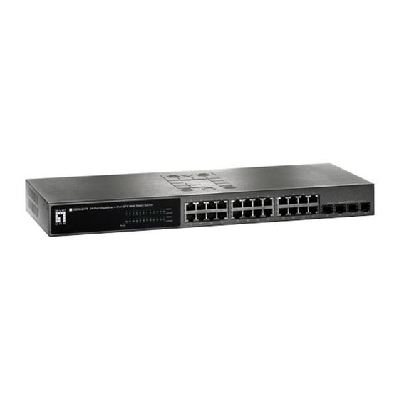
Overview LevelOne GSW-2476 is an intelligent Layer 2 switch with 24 10/100/ 1000BASE-T ports, four of which are combination ports with four SFP transceiver slots (see Figure 1-1, Ports 21-24). Port Status Indicators level GSW-2476 24 Port Gigabit w 4 Port SFP Web Smart Switch... -
Page 18: About Gsw-2476
The switch employs a wire-speed, non-blocking switching fabric. This permits simultaneous wire-speed transport of multiple packets at low latency on all ports. The switch also features full-duplex capability on all ports, which effectively doubles the bandwidth of each connection. The switch uses store-and-forward switching to ensure maximum data integrity. -
Page 19: Description Of Hardware
(purchased separately) is installed in a slot and has a valid link on its port, the associated RJ-45 port is disabled and cannot be used. The switch can also be configured to force the use of an RJ-45 port or SFP slot, as required. -
Page 20: Table 1-1 Port Status Leds
GSW-2476 BOUT 4 Port SFP Web Smart Switch Power Status LED Fast Ethernet Ports (Ports 1-24) Link/Act (Link/Activity) 1000 Mbps Condition Power Green 13 14 15 16 17 18 19 20 21 22 23 24 Power Port Status LEDs Figure 1-3 Port LEDs and Power LED... -
Page 21: Power Supply Socket
Power Supply Socket The power socket is located on the rear panel of the switch. The standard power socket is for the AC power cord. Features and Benefits Connectivity • 24 10/100/1000 Mbps ports for easy Gigabit Ethernet integration and for protection of your investment in legacy LAN equipment. -
Page 22: Expandability
GSW-2476 BOUT Expandability • 4 Small Form Factor Pluggable (SFP) transceiver slots (shared with 1000BASE-T ports) • Supports 1000BASE-SX, 1000BASE-LX and 1000BASE-ZX SFP transceivers. Performance • Transparent bridging. • Provides store-and-forward switching • Supports Jumbo frames up to 9.6 Kbytes •... -
Page 23: Network Planning
When networks are based on repeater (hub) technology, the distance between end stations is limited by a maximum hop count. However, a switch turns the hop count back to zero. So subdividing the network into smaller and more manageable segments, and linking them to the larger network by means of a switch, removes this limitation. -
Page 24: Application Examples
When the time comes for further expansion, just connect to another hub or switch using one of the Gigabit Ethernet ports built into the front panel, or a Gigabit Ethernet port on a plug-in SFP transceiver. -
Page 25: Central Wiring Closet
Central Wiring Closet With 24 parallel bridging ports (i.e., 24 distinct collision domains), this switch can collapse a complex network down into a single efficient bridged node, increasing overall bandwidth and throughput. In the figure below, the 1000BASE-T RJ-45 ports on the switch are providing 1 Gbps full-duplex connections for up to 24 local segments. -
Page 26: Remote Connections With Fiber Cable
A 1000BASE-SX (MMF) link can connect to a site up to 550 meters away, a 1000BASE-LX (SMF) link up to 10 km, and a 1000BASE-ZX link up to 70 km. This allows a switch stack to serve as a collapsed backbone, providing direct connectivity for a widespread LAN. -
Page 27: Making Vlan Connections
Making VLAN Connections The switch supports VLANs that can be used to organize any group of network nodes into separate broadcast domains. VLANs confine broadcast traffic to the originating group, and can eliminate broadcast storms in large networks. This provides a more secure and cleaner network environment. -
Page 28: Application Notes
1. Full-duplex operation only applies to point-to-point access (such as when a switch is attached to a workstation, server or another switch). When the switch is connected to a hub, both devices must operate in half-duplex mode. 2. For network applications that require routing between dissimilar network types, you can attach the switch directly to a multi-protocol router. -
Page 29: Installing The Switch
NSTALLING THE Selecting a Site GSW-2476 can be mounted in a standard 19-inch equipment rack or on a flat surface. Be sure to follow the guidelines below when choosing a location. • The site should: - be at the center of all the devices you want to link and near a power outlet. -
Page 30: Ethernet Cabling
1000BASE-T. • Protection from radio frequency interference emissions • Electrical surge suppression • Separation of electrical wires (switch related or other) and electromagnetic fields from data based network wiring • Safe connections with no damaged cables, connectors or shields RJ-45 Connector... -
Page 31: Equipment Checklist
GSW-2476 can be mounted in a standard 19-inch equipment rack or on a desktop or shelf. Mounting instructions for each type of site follow. Rack Mounting Before rack mounting the switch, pay particular attention to the following factors: QUIPMENT HECKLIST... - Page 32 NSTALLING THE WITCH • Temperature: Since the temperature within a rack assembly may be higher than the ambient room temperature, check that the rack-environment temperature is within the specified operating temperature range (see page C-2). • Mechanical Loading: Do not place any equipment on top of a rack-mounted unit.
-
Page 33: Figure 3-2 Attaching The Brackets
P o r t Figure 3-2 Attaching the Brackets 2. Mount the device in the rack, using four rack-mounting screws (not provided). Figure 3-3 Installing the Switch in a Rack S h a r e d S F P P o r t... -
Page 34: Desktop Or Shelf Mounting
2. Set the device on a flat surface near an AC power source, making sure there are at least two inches of space on all sides for proper air flow. 3. If installing a single switch only, go to “Connecting to a Power Source” at the end of this chapter. -
Page 35: Installing An Sfp Transceiver
3. Slide the transceiver into the slot until it clicks into place. Note: SFP transceivers are hot-swappable. The switch does not need to be powered off before installing or removing a transceiver. -
Page 36: Connecting To A Power Source
NSTALLING THE WITCH Connecting to a Power Source To connect a device to a power source: 1. Insert the power cable plug directly into the socket located at the back of the device. 2. Plug the other end of the cable into a grounded, 3-pin, AC power source. -
Page 37: Making Network Connections
Category 3 or better for 10BASE-T connections. Cabling Guidelines The RJ-45 ports on the switch support automatic MDI/MDI-X pinout configuration, so you can use standard straight-through twisted-pair cables to connect to any other network device (PCs, servers, switches, routers, or hubs). -
Page 38: Connecting To Pcs, Servers, Hubs And Switches
Figure 4-1 Making Twisted-Pair Connections 2. If the device is a PC card and the switch is in the wiring closet, attach the other end of the cable segment to a modular wall outlet that is connected to the wiring closet. (See “Network Wiring Connections”... -
Page 39: Network Wiring Connections
1. Attach one end of a patch cable to an available port on the switch, and the other end to the patch panel. 2. If not already in place, attach one end of a cable segment to the back of the patch panel where the punch-down block is located, and the other end to a modular wall outlet. -
Page 40: Fiber Optic Sfp Devices
50/125 or 62.5/125 micron multimode fiber optic cabling with an LC connector at both ends. Warning: the switch use lasers to transmit signals over fiber optic cable. The lasers are compliant with the requirements of a Class 1 Laser Product and are inherently eye safe in normal operation. -
Page 41: Figure 4-3 Making Connections To Sfp Transceivers
3. Connect one end of the cable to the LC port on the switch and the other end to the LC port on the other device. Since LC connectors are keyed, the cable can be attached in only one orientation. -
Page 42: Connectivity Rules
However, note that because switches break up the path for connected devices into separate collision domains, you should not include the switch or connected cabling in your calculations for cascade length involving other devices. -
Page 43: 100 Mbps Fast Ethernet Collision Domain
Table 4-3 Maximum 1000BASE-LX Fiber Optic Cable Length Fiber Diameter 9/125 micron single-mode fiber Table 4-4 Maximum 1000BASE-ZX Fiber Optic Cable Length Fiber Diameter 9/125 micron single-mode fiber 100 Mbps Fast Ethernet Collision Domain Table 4-5 Maximum Fast Ethernet Cable Length Type Cable Type 100BASE-TX... -
Page 44: Cable Labeling And Connection Records
For each piece of equipment, identify the devices to which it is connected. • Note the length of each cable and the maximum cable length supported by the switch ports. • For ease of understanding, use a location-based key when assigning prefixes to your cable labeling. -
Page 45: Configuring The Switch
(Internet Explorer 5.5 or above, or Mozilla Firefox 1.0 or above). Prior to accessing the switch from a web browser, be sure you have first performed the following tasks: 1. Configure the switch with a valid IP address, subnet mask, and default gateway. -
Page 46: Navigating The Web Browser Interface
Home Page When your web browser connects with the switch’s web agent, the home page is displayed as shown below. The home page displays the Main Menu on the left side of the screen and System Information on the right side. -
Page 47: Configuration Options
“Every visit to the page.” Panel Display The web interface displays an image of the switch's ports. A port turns green when the corresponding front-panel port is connected to another device. To show port numbers, place the mouse pointer over the port. -
Page 48: Main Menu
ONFIGURING THE WITCH Main Menu Using the onboard web agent, you can define system parameters, manage and control the switch, and all its ports, or monitor network conditions. The following table briefly describes the selections available from the web-browser interface. Menu... - Page 49 Table 5-2 Switch Main Menu (Continued) Menu PORTS Settings Storm Control Port Mirroring Cable Diagnostic TRUNKS Membership Settings VLANS VLAN Membership VLAN Port Config Settings Security IGMP Snoop Settings Status LOGOUT AVIGATING THE Description Configure the speed and duplex mode of the port.
-
Page 50: Web Configuration
• Gateway IP Address – IP address of the gateway router between the switch and management stations that exist on other network segments. (Default: 0.0.0.0) • MAC Address – The physical layer address of the switch. Port Information • Type – Indicates the port type. - Page 51 • Trunk – The trunk label. “T1” through “T8” are used as trunk labels. • Type – All trunks and ports on this switch are 10/100/1000Mbps • Trunk Status – Indicates the speed and duplex setting of the trunk. This can be changed on the TRUNKS >...
-
Page 52: Figure 5-3 Switch Information
ONFIGURING THE WITCH Web – Click STATUS, Overview. Figure 5-3 Switch Information... -
Page 53: Showing Port Statistics
Showing Port Statistics You can display statistics on network traffic from the ports. These statistics can be used to identify potential problems with the switch (such as a faulty port or unusually heavy loading). All values displayed have been accumulated since the last system reboot, but can be reset to zero by clicking the CLEAR button. - Page 54 ONFIGURING THE WITCH Parameter Received Multicast Packets The number of packets, delivered by this sub-layer to Received Broadcast Packets Transmitted Octets Transmitted Unicast Packets Transmitted Errors Received Medium Priority Packets Received Low Priority Packets Transmitted Medium Priority Packets Transmitted Low Priority Packets RMON Statistics Drop Events...
- Page 55 Table 5-3 Port Statistics (Continued) Parameter Undersize Frames Fragments Collisions Received Bytes Broadcast Frames CRC/Alignment Errors Oversize Frames Jabbers Description The total number of frames received that were less than 64 octets long (excluding framing bits, but including FCS octets) and were otherwise well formed.
- Page 56 ONFIGURING THE WITCH Parameter 64 Bytes Frames 65-127 Byte Frames 128-255 Byte Frames 256-511 Byte Frames 512-1023 Byte Frames 1024-1518 Byte Frames 5-12 Table 5-3 Port Statistics (Continued) Description The total number of frames (including bad packets) received and transmitted that were 64 octets in length (excluding framing bits but including FCS octets).
-
Page 57: Displaying System Name
ONFIGURATION Web – Click STATUS, Statistics. Figure 5-4 Port Statistics Displaying System Name You can easily identify the system by displaying the device name. Field Attributes • Switch Name – Name assigned to the switch system. 5-13... -
Page 58: Setting The Switch's Ip Address
Setting the Switch’s IP Address This section describes how to configure an IP interface for management access over the network. The IP address for this switch is 192.168.2.10 by default. To manually configure an address, you need to change the switch’s default settings (IP address 192.168.2.10 and netmask 255.255.255.0) to... -
Page 59: Manual Configuration
Web – Click System, LAN Settings. Enter the IP address, subnet mask and gateway, then click APPLY. Note that if you change the switch IP address, you must close the web interface and start a new session using the new IP address. -
Page 60: Tools
APPLY. Tools On the Tools page, you can restore the switch to default settings, upgrade the firmware of the switch, or restart the switch. Reset to Factory Defaults Force the switch to restore the original factory settings. -
Page 61: Figure 5-8 Reset To Factory Defaults
To Upgrade the switch system firmware, select “Upgrade Firmware” from the Tools drop-down list then click on the “Browse” button to select the firmware file. Click the APPLY button to upgrade the selected switch firmware file. Web – Click System, Tools, Upgrade Firmware. -
Page 62: Upload/Download Configuration
"Download", and then click on the "Browse" button to select the file. Set boot Image Web – Click SYSTEM, Tools, Set boot Image. To set the bootimage, click either “Image0“ or “Image1“to decide the active image, and then click APPlY. 5-18 Figure 5-10 Restart Switch Figure 5-11 Set boot Image... -
Page 63: Static Mac
You can also manually configure static MAC addresses that are assigned to specific ports on the switch. A static MAC address is bound to a specific port and will not be moved or aged out. You can define up to 24 static MAC addresses on the switch. -
Page 64: Counter Config
ONFIGURING THE WITCH Web – Click System, Static MAC. Enter the MAC address, VLAN ID, then click ADD button to add a new static MAC address. Figure 5-13 Static MAC Address Configuration Counter Config This page allows specific statistics to be selected for monitoring. It is possible to monitor up to five transmit counters and five receive counters, as well as 1 transmit byte counter and receive byte counter. -
Page 65: Port Configuration
Web – Click System, Counter Config Port Configuration You can use the Port Configuration page to manually fix the speed, duplex mode, and flow control. Field Attributes • Enable Jumbo Frames– Click to enable or disable Jumbo Frames. • Speed/Duplex – Allows you to manually set the port speed and duplex mode. -
Page 66: Figure 5-15 Port Configuration
ONFIGURING THE WITCH Web – Click PORTS, Settings. Figure 5-15 Port Configuration 5-22... -
Page 67: Storm Control
• Rate(number of frames per second) – The Rate field is set by a single drop-down list. The same threshold is applied to every port on the switch. When the threshold is exceeded, packets are dropped, irrespective of the flow-control settings. -
Page 68: Port Mirroring
WITCH Web – Click PORTS, Storm Control. This page enables you to set the broadcast storm control parameters for every port on the switch. Port Mirroring You can mirror traffic from any source port to a target port for real-time analysis. -
Page 69: Cable Diagnostic
Input rate-limiting in conjunction with port flow-control should be used to ensure that the total ingress bandwidth never exceeds the egress bandwidth. Web – Click PORTS, Port Mirroring. -
Page 70: Trunks Membership
ONFIGURING THE WITCH • Cable Status – Shows the cable length, operating conditions and isolates a variety of common faults that can occur on Category 5 twisted pair cabling. Web – Click PORTS, Port Mirroring. Trunks Membership This page allows you to create a maximum of eight trunks of up to eight ports each. -
Page 71: Trunk Configuration
• Trunk T1-T8 – These columns correspond to the eight trunks that are supported by the switch. To assign a port to a trunk, click on the radio button in the corresponding column, then click APPLY. Web – Click TRUNKS, Membership. To assign a port to a trunk, click the required trunk number, then click APPLY. -
Page 72: Vlan Settings
ONFIGURING THE WITCH • Flow Control – Allows flow control to be enabled or disabled. When the box is checked, flow control is enabled. • Ports – Indicates which ports belong to the trunk. Web – Click TRUNKS, Settings. VLAN Settings This page allows you to create and delete VLANs (Virtual LANs) and to change the VLAN membership and behaviour of individual ports. - Page 73 VLAN space by using this VLAN-in-VLAN hierarchy, preserving the customer’s original tagged packets, and adding SPVLAN tags to each frame (also called double tagging). Ports on the switch can be set to support QinQ when providing a direct link to a service provider's network.
- Page 74 ONFIGURING THE WITCH For QinQ operation, a customer port should be set to VLAN unaware and a provider port (trunk port) should be set to VLAN aware. • QinQ – A QinQ enabled port will accept packets up to 1526 bytes in length, which means double tag header frames can be accepted.
-
Page 75: Figure 5-21 Vlan Settings
Web – Click VLANS, VLAN Settings. Fill in the required settings for each interface, click Apply. Figure 5-21 VLAN Settings VLAN Memembership You can create up to 255 VLANs based on 802.1Q standard and delete VLANs (Virtual LANs) to change the VLAN membership and behaviour of individual ports. -
Page 76: Figure 5-22 802.1Q Vlan Configuration
ONFIGURING THE WITCH Web – Click VLANS, VLAN Membership. To add a new , type into the VLAN ID (1-4095) of the VLAN group you want the new group to be, then click Add to open up the 802.1Q VLAN Group window, on which you can configure VLAN membership. -
Page 77: Qos Settings
QoS (Quality of Service) is a mechanism that is used to prioritize certain traffic as it is forward through the switch. Traffic can be classified as High or Normal priority and, when the switch is heavily loaded, it is the Normal priority packets that are dropped first. -
Page 78: Security
DSCP to configure the related parameters. Security This page enables you to set up a management access filter on the switch. With the Management Access Filter Configuration table, you can create a list of up to 8 IP addresses or IP address groups that are allowed management access to the switch through the web interface or SNMP. -
Page 79: Figure 5-25 Management Access Filter Configuration
If anyone tries to access a management interface on the switch from an invalid address, the switch will reject the connection. Note: Invalid frames will not be able to access management interface, but normal forwarding is not impacted. -
Page 80: Igmp Snoop
Settings Field Attributes IGMP Snooping Configuration • IGMP Enabled - When enabled, the switch will monitor network traffic to determine which hosts want to receive multicast traffic. • Router Ports - Set if ports are conneting to the IGMP administrative routers. -
Page 81: Figure 5-26 Igmp Snooping Configuration
ONFIGURATION Web – Click IGMP Snoop, Settings. Figure 5-26 IGMP Snooping Configuration IGMP Status Show the IGMP Snooping statistics for the whole switch Field Attributes • VLAN ID - VLAN ID number. • Querier - Show whether Querying is enabled. -
Page 82: Figure 5-27 Igmp Snoop Status
ONFIGURING THE WITCH Web – Click IGMP Snoop, Status. Figure 5-27 IGMP Snoop Status 5-38... -
Page 83: Troubleshooting
Contact LevelOne Technical Support. • Verify that the switch and attached device are powered • Be sure the cable is plugged into both the switch and corresponding device. • If the switch is installed in a rack, check the connections to the punch-down block and patch panel. -
Page 84: Power And Cooling Problems
Then verify that you entered the correct IP address. Also, be sure the port through which you are connecting to the switch has not been disabled. If it has not been disabled, then check the network cabling that runs between your remote location and the switch. -
Page 85: Reset The Switch
ESET THE WITCH Reset the Switch As situation requires, you might want to reset the switch and to restore to the default settings. To reset the switch: 1. Unplug the power cord from the power socket. 2. Unplug all cables from the ports. - Page 86 ROUBLESHOOTING...
-
Page 87: Cables
Twisted-Pair Cable and Pin Assignments For 10BASE-T/100BASE-TX connections, a twisted-pair cable must have two pairs of wires. For 1000BASE-T connections the twisted-pair cable must have four pairs of wires. Each wire pair is identified by two different colors. For example, one wire might be green and the other, green with white stripes. -
Page 88: 10Base-T/100Base-Tx Pin Assignments
1, 2, 3, and 6, at one end of the cable, are connected straight through to pins 1, 2, 3, and 6 at the other end of the cable. When using any RJ-45 port on the switch, you can use either straight-through or crossover cable. -
Page 89: Straight-Through Wiring
(MDI-X), the two pairs of wires must be straight-through. (When auto-negotiation is enabled for any RJ-45 port on the switch, you can use either straight-through or crossover cable to connect to any device type.) You must connect all four wire pairs as shown in the following diagram to support Gigabit Ethernet connections. -
Page 90: Crossover Wiring
“X” (which indicates MDI), a crossover must be implemented in the wiring. (When auto-negotiation is enabled for any RJ-45 port on the switch, you can use either straight-through or crossover cable to connect to any device type.) You must connect all four wire pairs as shown in the following diagram to support Gigabit Ethernet connections. -
Page 91: 1000Base-T Pin Assignments
1000BASE-T Pin Assignments All 1000BASE-T ports support automatic MDI/MDI-X operation, so you can use straight-through cables for all network connections to PCs or servers, or to other switches or hubs. The table below shows the 1000BASE-T MDI and MDI-X port pinouts. These ports require that all four pairs of wires be connected. -
Page 92: Adjusting Existing Category 5 Cabling To Run 1000Base-T
ABLES Note that when testing your cable installation, be sure to include all patch cables between switches and end devices. Adjusting Existing Category 5 Cabling to Run 1000BASE-T If your existing Category 5 installation does not meet one of the test parameters for 1000BASE-T, there are basically three measures that can be applied to try and correct the problem: 1. -
Page 93: Specifications
Physical Characteristics Ports 20 10/100/1000BASE-T, with auto-negotiation 4 10/100/1000BASE-T shared with 4 SFP transceiver slots. Network Interface Ports 1-24: RJ-45 connector, auto MDI/X 10BASE-T: RJ-45 (100-ohm, UTP cable; Category 3 or better) 100BASE-TX: RJ-45 (100-ohm, UTP cable; Category 5 or better) 1000BASE-T: RJ-45 (100-ohm, UTP or STP cable;... -
Page 94: Switch Features
Power Supply Internal, auto-ranging transformer: 100 to 240 VAC, 50 to 60 Hz Power Consumption 28 Watts Maximum Current 0.25 A @ 115 VAC 0.12 A @ 230 VAC Switch Features Forwarding Mode Store-and-forward Throughput Wire speed Management Features In-Band Management... -
Page 95: Standards
Software Loading HTTP in-band Standards IEEE 802.3-2005 Ethernet, Fast Ethernet, Gigabit Ethernet IEEE 802.1Q Virtual LAN IEEE 802.1X, Port-Based Network Access Control, 2001 ISO/IEC 8802-3 Compliances CE Mark Emissions FCC Class A TANDARDS... - Page 96 PECIFICATIONS...
-
Page 97: Auto-Negotiation
10BASE-T IEEE 802.3 specification for 10 Mbps Ethernet over two pairs of Category 3 or better UTP cable. 100BASE-TX IEEE 802.3u specification for 100 Mbps Fast Ethernet over two pairs of Category 5 or better UTP cable. 1000BASE-LX IEEE 802.3z specification for Gigabit Ethernet over two strands of 50/125, 62.5/125 or 9/125 micron core fiber cable. - Page 98 LOSSARY Bandwidth The difference between the highest and lowest frequencies available for network signals. Also synonymous with wire speed, the actual speed of the data transmission along the cable. Collision A condition in which packets transmitted over the cable interfere with each other.
-
Page 99: Gigabit Ethernet
Full Duplex Transmission method that allows two network devices to transmit and receive concurrently, effectively doubling the bandwidth of that link. Gigabit Ethernet A 1000 Mbps network communication system based on Ethernet and the CSMA/CD access method. IEEE Institute of Electrical and Electronic Engineers. IEEE 802.3 Defines carrier sense multiple access with collision detection (CSMA/CD) access method and physical layer specifications. -
Page 100: Network Diameter
LOSSARY Layer 2 Data Link layer in the ISO 7-Layer Data Communications Protocol. This is related directly to the hardware interface for network devices and passes on traffic based on MAC addresses. Light emitting diode used for monitoring a device or network condition. Link Segment Length of twisted-pair or fiber cable joining a pair of repeaters or a repeater and a PC. -
Page 101: Virtual Lan (Vlan)
Redundant Power Supply (RPS) A backup power supply unit that automatically takes over in case the primary power supply should fail. RJ-45 Connector A connector for twisted-pair wiring. Switched Ports Ports that are on separate collision domains or LAN segments. Telecommunications Industry Association Transmission Control Protocol/Internet Protocol (TCP/IP) Protocol suite that includes TCP as the primary transport protocol, and IP... - Page 102 LOSSARY Glossary-6...
-
Page 103: Index
Numerics 10 Mbps connectivity rules 4-7 100 Mbps connectivity rules 4-7 1000 Mbps connectivity rules 4-6 1000BASE-LX fiber cable lengths 4-7 1000BASE-SX fiber cable lengths 4-6 1000BASE-T pin assignments B-5 ports 1-3 1000BASE-ZX fiber cable lengths 4-7 100BASE-TX cable lengths 4-7 ports 1-3 10BASE-T ports 1-3 10BASE-T/100BASE-TX pin... - Page 104 NDEX installation connecting devices to the switch 4-2 desktop or shelf mounting 3-6 port connections 4-1 power requirements 3-1 problems A-2 rack mounting 3-3 site requirements 3-1 wiring closet connections 4-7 IP address setting 5-14 laser safety 4-4 LC port connections 4-4...
- Page 105 1-2 switching, introduction to 2-1 temperature within a rack 3-4 troubleshooting in-band access A-2 power and cooling problems A-2 switch indicators A-1 twisted-pair connections 4-1 user password 5-15 VLANs tagging 2-5 Web interface access requirements 5-1 configuration buttons 5-3...
- Page 106 NDEX Index-4...
- Page 108 GSW-2476 E082006-JC-R01 149100011100H...
Need help?
Do you have a question about the ProCon GSW-2476 and is the answer not in the manual?
Questions and answers