
Related Manuals for LevelOne FEP-0840


Summary of Contents for LevelOne FEP-0840
-
Page 1: Quick Guide
FEP-0840 8-Port Web Smart PoE Switch Quick Guide & User Manual V1.0 Digital Data Communications Asia Co., Ltd. http://www.level1.com http://www.level1.com... - Page 2 Quick Guide Step1. Connect POE SWITCH with AC power cord to 100~240VAC. Step2. Connect the PoE AP device to LAN port 1, and your PC to LAN port 8 as the following connection. Step3. Turn on the power switch, it will light on the PWR LED, and perform self- diagnostic test.
- Page 3 Click the icon “PoE”, and then select “PoE Step6. Setting”. Select “Enable” and c lick on Port Step7. No.1 Update to power on the connected PoE AP “PoE Scheduling” to select time schedule for device for Port 1. You may also click Power on/off scheduling control.
-
Page 4: Table Of Contents
Table of Contents Introduction ........................ 7 Features ........................8 Power on Switch ....................8 LED Indicators ....................8 Switch Installations ..................... 9 Package Contents ....................9 Hardware Overview ..................9 Preparations for Site Installation..............11 Desktop Installation ..................11 Cabling Requirements ..................12 Power Connection ................... - Page 5 Port Management .................... 26 4.5.1 Port Configuration ................26 4.5.2 Port Mirroring ..................27 4.5.3 Bandwidth Control ................28 4.5.4 Broadcast Storm Control ..............34 VLAN Setting ....................35 4.6.1 VLAN Mode ..................35 4.6.2 VLAN Member ................... 36 Per Port Counter ..................... 39 QoS Setting .......................
- Page 6 Appendix B: Troubleshooting ..................54 B.1 Can NOT Access Web Page? ................54 B.2 Forget IP Address, User ID, and Password? ..........54 http://www.level1.com...
-
Page 7: Introduction
1 Introduction The POE SWITCH is an 8-Port Web-Smart Midspan PoE Switch with power on/off scheduling control. The web smart features are designed to deliver high levels of performance that are commensurate with Fast Ethernet networking, and to provide simple and easy installation in an environment where the power over Ethernet (PoE) are required for remote PoE devices. -
Page 8: Features
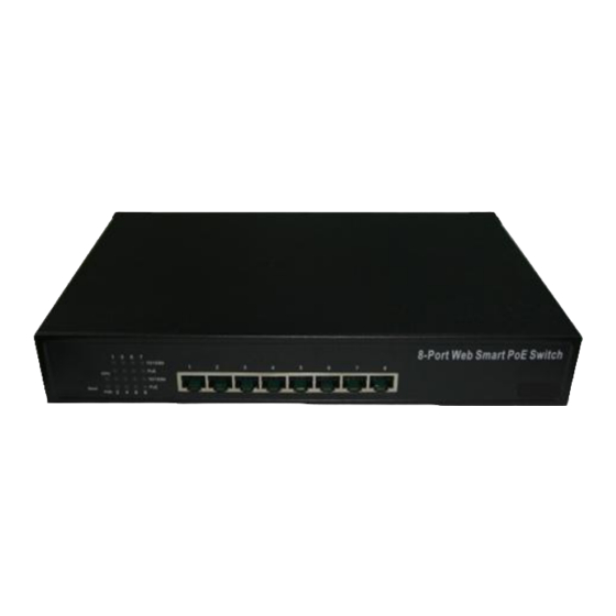
2 Features The POE SWITCH web smart PoE switch is equipped with an 8-port RJ45 connector for Fast Ethernet, and the corresponding LED indicators for each port. In addition, a built-in push button is provided for default reset, which is useful to reset back to the default IP address, user ID, and password. -
Page 9: Switch Installations
3 Switch Installations This chapter lists the package contents, and describes the hardware and detailed procedures for installation of the web management switch. For a quick setup, please refer to the quick guide at the beginning of this manual. 3.1 Package Contents Make sure that you have all the necessary accessories that come with your package, before you start the installation of the web management switch. -
Page 10: Reset Button
LED Indicators: LED indicators display the network connection and PoE status of the switch. 100BASE-TX Fast Ethernet with PoE Ports (Port 1~8): These ports are with passive PoE capabilities, and will supply power to the connected PoE device under the control of the web management. This feature allows users to freely and safely mix legacy and PoE compatible devices on their network. -
Page 11: Preparations For Site Installation
3.3 Preparations for Site Installation You can mount POE SWITCH either on desktop or on a 19-inch rack. If you plan to mount the switch on desktop, please choose a steady, level surface in a well-ventilated area that is free from excessive dust. In any case, the installation site chosen for your switch has to comply with the following requirements: ... -
Page 12: Cabling Requirements
They also allow adequate ventilation space when you place the switch on top of another device. The location you choose to install your switch and the way you configure your network may greatly affect its performance. Do not place more than 1.5kg (6.6lbs) of weight on the top of the switch. Leave at least 10cm of space around the switch to allow proper heating dissipation. -
Page 13: Power Connection
3.6 Power Connection The POE SWITCH is equipped with an internal power supply unit, which allows a power connection to a wide range of input voltages from 100 to 240 VAC with 50 ~ 60Hz. To establish its power connection, simply plug the female end of the power cord into the power connector on the rear of the switch and the male end of the power cord into a suitable power outlet. -
Page 14: Reset To Default
Step7. Install the rack mount kit on the 19" rack if needed. Step8. Refer to Chapter 4 for further networking configurations. 3.8 Reset to Default When forgot the web management IP address, user ID, or password, you may use the reset button for the factory default settings. - Page 15 Step5. Enter "192.168.2.1" from PC web browser to connect to web management. Step6. Enter "admin" for username and "system" for password, and click OK button to login to web management. http://www.level1.com...
-
Page 16: Web Management
4 Web Management The POE SWITCH can be configured on web page, including administrator, bandwidth management, VLAN setting, per port counter, trunk setting, QoS setting, security filter configuration, backup/recovery, miscellaneous, logout, etc. The web browsers, such as IE 6.0~7.0, Firefox 2.0~3.0, can be used to configure t he web smart switch. All the web management functions will be illustrated in t his chapter. - Page 17 To set your computer IP address in the same subnet as the switch, please follow the steps to change the computer IP address: Step 1. Double click on the network connection status icon on the task bar. This should bring up a window showing the status of the current network connection. If there is no network status icon on the task bar, please go to the “Start ->...
- Page 18 Click on “Use the following IP address” button and enter the computer‟s IP Step 4. address manually. This IP address must be on the same subnet as the switch but different from the switch‟s IP. Please make sure the IP is not used by other network device.
-
Page 19: Web Management
4.2 Web management After you have properly configured the computer and switch‟s IP, you can get into the web management by the following steps: Step 1. Run the Internet Explorer Step 2. Enter “192.168.2.1” for the web management IP address. Step 3. -
Page 20: Administrator
4.3 Administrator The Administrator section includes the management functions as the following: Authentication Configuration System IP Configuration System Status Load Default Setting Firmware Update Reboot Device 4.3.1 Authentication Configuration This page shows the information for authentication configuration. User can set new Username and Password in this page. -
Page 21: System Ip Configuration
4.3.2 System IP Configuration This page shows system configuration including the current IP address, Subnet mask, and Gateway. User can configure the IP settings, Subnet Mask, Gateway as below: IP address: The default IP is 192.168.2.1 Subnet Mask: The default is 255.255.255.0. Gateway: Assign the network gateway for the web smart switch. -
Page 22: Load Default Setting
Comment: Comment note for the switch. System Version: Displays the switch‟s firmware version. Click Update button for exit. 4.3.4 Load Default Setting The switch can be set to the default values by clicking the “Load” button. *Note: This will NOT change the user ID, password, and IP configurations. It only restore all default settings related to switch behavior. -
Page 23: Poe
4.3.6 Reboot Device Click “Confirm" button to reboot the device. *Note: The reboot is for software base instead of hardware base 4.4 PoE This PoE section describes the PoE functions, and display the power on/off status of each port. 4.4.1 PoE Setting http://www.level1.com... -
Page 24: Poe Power Delay
4.4.2 PoE Power Delay This PoE power on/off will be delayed in accord with the delay mode. http://www.level1.com... -
Page 25: Poe Scheduling
4.4.3 PoE Scheduling The PoE on/off control will be scheduling in accord with the schedule mode. http://www.level1.com... -
Page 26: Port Management
4.5 Port Management The Port Management section includes the management functions as the following: Port Configuration, Port Mirroring, Bandwidth Control, Broadcast Storm Control, POE. 4.5.1 Port Configuration In Port Configuration, you can set and view the operation mode for each port. Auto: Enable and Disable. -
Page 27: Port Mirroring
Click "Update" to make the configuration effective. Current Status: Displays current port status. Setting Status: Displays current status. Click "Update" to make the configuration effective 4.5.2 Port Mirroring The port mirroring function is accomplished by setting the following items. Destination port: The port mirroring function will lower the network throughput, and it‟s recommended to set “only one”... -
Page 28: Bandwidth Control
This means all packets received at port 1 ~ port 4 will be copied to port 5, port 6, port 7 and port 8. Note that the more source ports and destination ports is set, the lower network throughput is available for normal traffic. 4.5.3 Bandwidth Control This page allows the bandwidth setting for each port. - Page 29 (a) Low bandwidth for TX Example 1: The TX number of the port1~4 is set to 10, 20, 30, 40 respectively, and Speed base is set to “low”. The real bandwidth comes from the formula of 32Kbps*10, 32Kbps*20, 32Kbps*30 and 32Kbps*40 respectively. After the “update” button is executed, the real bandwidth will show up in TX fields.
- Page 30 (b) High bandwidth for TX xample 2: The TX number of the port1~4 is set to 10, 20, 30, 40 respectively, and Speed base is set to “High”. The real bandwidth comes from the formula of 512Kbps*10, 512Kbps*20, 512Kbps*30, and 512Kbps*40 respectively. After the “update” button is executed, the real bandwidth will show up in TX fields.
- Page 31 (c) Low bandwidth for RX Example 3: The RX bandwidth number of the port 5~ port 8 is set to 50, 60, 70, 80 respectively, and Speed base is set to “low”. The real bandwidth comes from the formula of 32Kbps*50, 32Kbps*60, 32Kbps*70, and 32Kbps*80 respectively after the “update”...
- Page 32 (d) High bandwidth for RX Example 4: The RX bandwidth number of the port 5~ port 8 is set to 50, 60, 70, 80 respectively, and Speed base is set to “high”. The real bandwidth comes from the formula of 512Kbps*50, 512Kbps*60, 512Kbps*70 and 512Kbps*80 respectively.
- Page 33 Limitation of the bandwidth control The actual bandwidth should be less than the cable link speed. For 100Mbps link speed, the bandwidth setting should be less than 196 if the bandwidth is set to “high”. For 10Mbps link speed, the bandwidth setting should be less than 20 if the bandwidth base is set to “high”.
-
Page 34: Broadcast Storm Control
4.5.4 Broadcast Storm Control The switch implements a broadcast storm control mechanism. Tick the check boxes to have them beginning to drop incoming broadcast packets if the received broadcast packet counts reach the threshold defined. Each port‟s broadcast storm protection function can be enabled individually by ticking the check boxes. -
Page 35: Vlan Setting
4.6 VLAN Setting A Virtual LAN (VLAN) is a logical network grouping that limits the broadcast domain, which would allow you to isolate network traffic, so only the members of the same VLAN will receive traffic from the ones of the same VLAN. Basically, creating a VLAN from a switch is logically equivalent of reconnecting a group of network devices to another Layer 2 switch. -
Page 36: Vlan Member
VLAN Mode: Port based/Tag based VLAN mode can be switched back and forth. Add tag means the outgoing packet of the selected port will be inserted a 802.1Q tag. Use this setting for your Uplink/Downlink Ports in your VLAN Tagged Network. Original means the outgoing packet of the selected port keep the original packet received at the source port. - Page 37 VLAN Member in Tag Based Mode In Tag Based Mode you need to define and configure your VLAN groups. Since you want the handover to other switches take place smoothly, the VLAN IDs (Numbers) need to be alike on the rest of your network. On other switches you may have the chance to configure names for your reference, but only the numbers are meaningful.
-
Page 38: Multi To 1 Setting
4.6.3 Multi to 1 Setting Multi-to-1 VLAN is used in CPE side of Ethernet-to-the-Home and is exclusive from VLAN member setting for VLAN setting. When VLAN member setting is updated, multi- to-1 setting will be void and vice versa. The “Disable port” means the port will be excluded in this setting. -
Page 39: Per Port Counter
4.7 Per Port Counter This page provides port counter for each port. There are 4 groups of statistics in total. These 4 categories cannot work simultaneously. Once you change the counter category, the counter will be cleared automatically. Transmit packet& collision: This category shows the packets outgoing from the switch and the count of collision. -
Page 40: Qos Setting
4.8 QoS Setting The Quality of Service(QoS) Setting includes Priority Mode and Class of Service (CoS) Configuration. QoS refers to mechanisms in the network software that make the actual determination of which packets have priority. CoS refers to feature sets, or groups of services, that are assigned to users based on company policy. -
Page 41: Class Of Service Configuration
4.8.2 Class of Service Configuration There are 4 types of CoS for this setting; TCP/UDP port, TOS/DS, 802.1p, and physical port. The user can select more than one item for each port. Note that if more than one type of CoS is selected, the switch will arrange the packet to the assigned queue according the following priority: TCP/UDP port the first, ToS/DS the second, 802.1p the third, and physical port the last. - Page 42 http://www.level1.com...
-
Page 43: Security
4.9 Security The Security section describes the functions of MAC Address Binding, MAC Address Scan, TCP/UDP Filter, and Web Security. 4.9.1 MAC Address Binding This function specifies the relationship between the physical port and the MAC address. Only the packet with specified source MAC address can be forwarded. By assigning the MAC address to each port, the network administrator can prevent the unauthorized user from accessing the switch. -
Page 44: Mac Address Scan
4.9.2 MAC Address Scan This shows the MAC addresses for packets through the selected port. 4.9.3 TCP/UDP Filter By selecting the TCP/UDP port, the network administrator can optionally block some specific functions. There are two kinds of protocol filter functions. The Forward function forwards packets of the selected protocol and drops other protocols. -
Page 45: Web Management Filter
4.9.4 Web Management Filter 4.10 Spanning Tree http://www.level1.com... -
Page 46: Stp Bridge Settings
4.10.1 STP Bridge Settings 4.10.2 STP Port Settings 4.10.3 Loopback Detection Settings http://www.level1.com... - Page 47 http://www.level1.com...
-
Page 48: Trunk Setting
4.11 Trunk Setting Trunk setting is used to set trunk group for load balance and auto-backup. The switch supports two trunk group, and each trunk consists of 2~4 ports. Trunk hash algorithm can be selected according to 4 different options. Port ID: Among the trunk member ports, the packet will be distributed based on the port Among the trunk member ports, the packet will be distributed based on the source MAC address. -
Page 49: Dhcp Relay Agent
4.12 DHCP Relay Agent 4.13 NTP Setting http://www.level1.com... -
Page 50: Backup/Recovery
4.14 Backup/Recovery This function is used to backup/recovery the switch configuration. The user can save the configuration file to a specified file name. If the user wants to recover the original configuration, which is saved at the specified path, just enter the password and then press the “Update”... -
Page 51: Miscellaneous
4.15 Miscellaneous Miscellaneous setting is used to configure output queue aging time, VLAN stride and IGMP snooping. Output queue aging: This function is used to avoid the poor utilization of the switch. When a packet is stored in a switch for a long time, it will expire from the allowable time defined by the protocol and become a useless packet. -
Page 52: Appendix A: Product Specifications
Appendix A: Product Specifications IEEE 802.3 10BaseT IEEE 802.3u 100BaseTX IEEE Standards IEEE 802.3x Flow Control Interface: 8 port x 10/100BaseT(X) Switch with PoE Control Hardware MAC Address: 1K Buffer Memory: 512K bits Transmission Packet Store and Forward 10BaseT Cat. 3, 4, 5 UTP/STP Transmission Media 100BaseTX Cat. - Page 53 Dimensions 266 × 160 × 44 mm (L x W x H) Humidity 10 to 90% RH (non-condensing) Weight 1.6 kg Operating: 0 to 60℃ Temperature Storage: -20 to 90℃ http://www.level1.com...
- Page 54 Appendix B: Troubleshooting This appendix is to help identify and solve the problems. If the web smart switch is not working correctly with your network, check the items as the following; Make sure the Power is ON (Check the Power LED). ...
Need help?
Do you have a question about the FEP-0840 and is the answer not in the manual?
Questions and answers