
Subscribe to Our Youtube Channel
Related Manuals for LevelOne GSW-5270


Summary of Contents for LevelOne GSW-5270
-
Page 1: User Manual
LevelOne GSW-5270 48-Port TP Fast Ethernet and 4-Port TP Gigabit w/ 2-Port shared SFP Web Smart Switch User Manual... - Page 3 Safety FCC Warning This equipment has been tested and found to comply with the regulations for a Class A digital device, pursuant to Part 15 of the FCC Rules. These limits are designed to provide reasonable protection against harmful interference when the equipment is operated in a commercial environment.
-
Page 4: Table Of Contents
Table of Content INTRODUCTION...............1 1.1..............2 EATURES 1.2............3 ACKAGE ONTENT HARDWARE DESCRIPTION ...........5 2.1...............5 RONT ANEL LED Indicators:..............5 100BASE-TX Fast Ethernet Ports (Port 1~48):....5 1000BASE-T Gigabit Ethernet Ports (Port 49~52):...5 Combo mini-GBIC Ports (Port 49~50).......5 Reset: ................6 2.2. LED I ............7 NDICATORS... - Page 5 Trunk Setting ..............30 Mirror Setting..............31 IEEE 802.1p Default Priority ...........32 Broadcast Storm Control Setting........32 5.2............33 YSTEM ETTING System Information ............33 System Setting ..............34 Trap Setting ..............35 Password Setting ............36 Statistic ................37 Factory Reset ..............38 Backup Setting ..............38 Firmware Upload .............39 System Reboot..............39 Logout ................39 APPENDIX ..............41...
-
Page 6: Introduction
1. INTRODUCTION GSW-5270 is a high-density smart switch that provides the ultimate bandwidth and versatile features for large workgroups or backbones with the aggregated 17.6Gbps bandwidth. We offer outstanding connectivity by providing different 48-port TP 10/100Mbps with 4-port Gigabit TP and 2-Port mini-GBIC SFP... -
Page 7: Features
1.1. Features 48 x 100BASE-TX Auto-negotiation Fast Ethernet ports 4 x 1000BASE-T Auto-negotiation Gigabit Ethernet ports 2 x 1000BASE-T Combo mini-GBIC (Auto-Sense) Gigabit Ethernet for optional mini-GBIC transceiver to extend distance, share with 2 1000BASE-T ports All ports support auto MDI/MDIX, so there is no need to use cross-over cables or an up-link port Half duplex transfer mode for connection speed 10Mbps and 100Mbps... -
Page 8: Package Content
1.2. Package Content Open the shipping cartons of the Switch and carefully unpacks its contents. The carton should contain the following items: - GSW-5270 Web Smart Switch - Power Cord - Rack-mount Kit - Rubber Feet - CD Manual/Utility GSW-5270... -
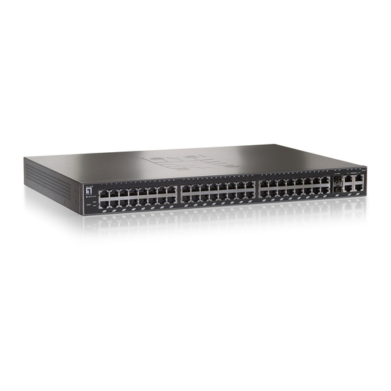
Page 10: Hardware Description
2. HARDWARE DESCRIPTION 2.1. Front Panel LED Indicators: Comprehensive LED indicators display the status of the switch and the network (see the LED Indicators chapter below). 100BASE-TX Fast Ethernet Ports (Port 1~48): These ports support network speeds of either 10Mbps or 100Mbps, and can operate in half- and full- duplex transfer modes. -
Page 11: Reset
Reset: The Reset button is to reset all the setting back to the factory default. Note: Note 1. When the port was set to “Forced Mode”, the Auto MDI/MDIX will be disabled. 2. Be sure that you recorded the setting of your device, else all the setting will be erased when pressing the “Reset”... -
Page 12: Led Indicators
2.2. LED Indicators The front panel LEDs provides instant status feedback, and, helps monitor and troubleshoot when needed. Power and System PWR: Power Indicator When the Power LED lights on, the Switch is receiving power. When the Power turns off or the power cord has improper connection. -
Page 13: Mini-Gbic Port 49~50 Status
mini-GBIC Port 49~50 Status Link/ACT: Link/Activity When the Link/ACT LED lights on, the respective port is successfully connected to a Gigabit Ethernet network. Blinking : When the Link/ACT LED is blinking, the port is transmitting or receiving data on the Gigabit Ethernet network. -
Page 14: Rear Panel
2.3. Rear Panel The rear panel of the Switch consists of an AC power connector and Reset button. The following shows the rear panel of the Switch. AC Power Connector: This is a three-pronged connector that supports the power cord. Plug in the female connector of the provided power cord into this connector, and the male into a power outlet. -
Page 16: Installation
3. INSTALLATION The site where you install the hub stack may greatly affect its performance. When installing, consider the following pointers: Install the Switch in a fairly cool and dry place. See Technical Specifications for the acceptable temperature and humidity operating ranges. Install the Switch in a site free from strong electromagnetic field generators (such as motors), vibration, dust, and direct exposure to sunlight. -
Page 17: Rack Mounting
3.1. Rack Mounting The switch can be mounted in an EIA standard-size, 19-inch rack, which can be placed in a wiring closet with other equipment. Attach the mounting brackets at the switch’s front panel (one on each side), and secure them with the provided screws. -
Page 18: Connecting Network Cable
3.2. Connecting Network Cable The Switch supports 48-port 10Mbps Ethernet or 100Mbps Fast Ethernet and it runs both in half and full duplex mode using two pair of Category 5 cable. The Switch also supports 4-port 1000Mbps Gigabit Ethernet that runs in Auto-negotiation mode and 10Mbps Ethernet or 100Mbps Fast Ethernet that runs both in half and full duplex mode and 1000Mbps Gigabit Ethernet runs in full duplex mode using four pair of Category 5 Cable. -
Page 20: Web Management Utility
4. WEB MANAGEMENT UTILITY Through the Web Browser you can configure the Switch such as VLAN, Port Trunking, and Broadcast Storm … etc. With the attached Web Management Utility, you can easily discover all the Web Management Switch, assign the IP Address, changing the password and upgrading the new firmware. -
Page 21: Discovery List
Discovery List This is the list where you can discover all the Web management devices in the entire network. By pressing the “Discovery” button, you can list all the Web Management devices in the discovery list. Double click or press the “Add to monitor list” button to select a device from the Discovery List to the Monitor List. -
Page 22: Monitor List
Monitor List All the Web Smart Device in the Monitor List can be monitored; you can also receive the trap and show the status of the device. System word definitions in the Monitor List: S: Shows the system symbol of the Web-Smart device, represent for device system is not alive. - Page 23 View Trap: The Trap function can receive the events that happen from the Web Management Switch in the Monitor List. There is a light indicator behind the “View Trap” button, when the light indicates in green, it means that there is no trap transmitted, and else when it indicates in red, it means that there is new trap transmitted, this is to remind us to view the trap.
-
Page 24: Device Setting
Device Setting You can set the device by using the function key in the Device Setting Dialog box. Configuration Setting: In this Configuration Setting, you can set the IP Address, Subnet Mask, Gateway, Set Trap to (Trap IP Address), System name, Location and DHCP function. Select the device in the Discovery list or Monitor List and press this button, then the Configuration Setting window will pop out, after filling up the data that you want to change, you must fill up... - Page 25 Firmware Upgrade: When the device has a new function, there will be a new firmware to update the device, use this function to update. Firmware Upgrade Access Web: Double click the device in the Monitor List or select a device in the Monitor List and press this “Web Access”...
-
Page 26: Toolbar
Toolbar The toolbar in the Web Management Utility have four main tabs, File, View, Options and Help. In the “File TAB”, there are Monitor Save, Monitor Save As, Monitor Load and Exit. Monitor Save: To record the setting of the Monitor List to the default, when you open the Web Management Utility next time, it will auto load the default recorded setting. -
Page 27: Configuring The Switch
4.2. Configuring the Switch The 48+4-Port 10/100/1000Mbps Gigabit Ethernet Web Smart Switch has a Web GUI interface for smart switch configuration. The Switch can be configured through the Web Browser. A network administrator can manage, control and monitor the switch from the local LAN. This section indicates how to configure the Switch to enable its smart functions Default Setting Default IP Address: 192.168.0.1... - Page 28 Or through the Web Management Utility, you do not need to remember the IP Address, select the device shown in the Monitor List of the Web Management Utility to settle the device on the Web Browser. When the following dialog page appears, remain enter the default password "admin"...
-
Page 30: Web Configuration
5. WEB CONFIGURATION When the main page appears, find the Configuration menu in the left side of the screen. Click on the setup item that you want to configure. There are fifteen options: Port Setting, IEEE 802.1Q VLAN Settings, Trunk Setting, Mirror Setting, IEEE 802.1p Default Priority, Broadcast Strom Control Setting, System Information, System Setting, Trap Setting, Password Setting, Statistics, Factory Reset, Backup Setting, Firmware... -
Page 31: Setup
5.1. Setup Find that there are eight items, including Port Setting, IEEE 802.1Q VLAN Settings, Trunk Setting, Mirror Setting, IEEE 802.1p Default Priority and Broadcast Strom Control Setting in Setup menu. Port Settings In Port Settings menu, this page will show each port’s status, selected drop down menu to set each port’s Speed, and QoS priority then press “Apply”... - Page 32 Speed: The 1~48 100BASE-TX port connections can operate in Forced Mode settings (100M Full, 100M Half, 10M Full, 10M Half), Auto, or Disable. The default setting for all ports are Auto. The 49~52 1000BASE-T port connections can operate in Forced Mode settings (1000M Full, 100M Full, 100M Half, 10M Full, 10M Half), Auto, or Disable.
-
Page 33: Ieee 802.1Q Vlan
IEEE 802.1Q VLAN A VLAN is a group of ports that can be anywhere in the network, but communicate as though they were in the same area. VLANs can be easily organized to reflect department groups (such as R&D, Marketing), usage groups (such as e-mail), or multicast groups (multimedia applications such as video conferencing), and therefore help to simplify network management by allowing users to move devices to a new... - Page 34 Delete: Click to delete selected VID. Delete VID To change exist IEEE 802.1Q VLAN setting, press the VID to modify that IEEE 802.1Q VLAN setting. Modify VID Modify VID Asymmetric VLAN: If asymmetric is enabled and port 1, for example, receives an untagged packet, the switch will apply the PVID of port 1 to tag this packet, the packet then will be forwarded.
-
Page 35: Trunk Setting
Trunk Setting The Trunking function enables the cascading of two or more ports for a combined larger bandwidth. Up to six Trunk groups may be created, each supporting up to 8 ports. Add a Trunking Name and select the ports to be trunked together, and click Apply to activate the selected Trunking groups. -
Page 36: Mirror Setting
Mirror Setting Port Mirroring is a method of monitoring network traffic that forwards a copy of each incoming and/or outgoing packet from one port of the Switch to another port where the packet can be studied. This enables network managers to better monitor network performances. -
Page 37: Ieee 802.1P Default Priority
IEEE 802.1p Default Priority This feature displays the status Quality of Service priority levels of each port, and for packets that are untagged, the switch will assign the priority in the tag depending on your configuration. IEEE 802.1p Default Priority Setting Broadcast Storm Control Setting The Broadcast Storm Control feature provides the ability to control the receive rate of broadcasted packets. -
Page 38: System Setting
5.2. System Setting Find that there are nine items, including System Information, System Setting, Trap Setting, Password Setting, Statistics, Factory Reset, Backup Setting, Firmware Upload and System Reboot in System menu. System Information Press on the “System Information” to present the system information status on this screen, it will show the Product Name, Firmware Version, Protocol Version, MAC Address, System Name, Location Name, IP Address, Subnet Mask, Default... -
Page 39: System Setting
System Setting The System Setting includes IP Information and System information. There are two ways for the switch to attain IP: Static and DHCP (Dynamic Host Configuration Protocol). When using static mode, the IP Address, Subnet Mask and Gateway can be manually configured. When using DHCP mode, the Switch will first look for a DHCP server to provide it with an IP address, network mask, and default gateway before using the default or previously entered settings. -
Page 40: Trap Setting
Trap Setting By configuring the Trap Setting, it allows Web Management Utility to monitor specified events on this Web-Smart Switch. By default, Trap Setting is Disabled. When the Trap Setting is Enabled, enter the Destination IP address of the managing PC that will receive trap information. -
Page 41: Password Setting
Password Setting Setting a password is an invaluable tool for managers to secure the Web Smart Switch. After entering the old password and the new password two times, press Apply for the changes to take effect. If you forget the password, press the “Reset” button in the front panel of the Switch, the current setting includes VLAN, Port Setting…... -
Page 42: Statistic
Statistic The Statistic Menu screen will show the status of each port packet count. Statistics Refresh: To renew the details collected and displayed. Clear Counter: To reset the details displayed. To view the statistics of individual ports, click one of the Port ID Port Statistics... -
Page 43: Factory Reset
Factory Reset The Factory Reset helps you to reset the device back to the default setting from the factory. All of the configuration will be reset, the IP address of the device will be set to default setting 192.168.0.1. Factory Reset Backup Setting The backup setting help you to backup the current setting of the Switch. -
Page 44: Firmware Upload
Firmware Upload The Firmware Upload helps you to backup or upload firmware from/to the Switch. Once you need to backup the current firmware of the Switch, press the “Backup” button to save the current firmware of the Switch; To restore or upgrade firmware to the Switch, you must specify the firmware file and press “Upload”... -
Page 46: Appendix
6. APPENDIX 6.1. Technical Specifications General IEEE 802.3 10BASE-T Ethernet IEEE 802.3u 100BASE-TX Fast Ethernet Standards IEEE 802.3ab 1000BASE-T Gigabit Ethernet IEEE 802.3z 1000BASE-SX/LX Gigabit Ethernet Protocol CSMA/CD Ethernet: 10Mbps (half-duplex), 20Mbps (full-duplex) Data Transfer Fast Ethernet: 100Mbps (half-duplex), 200Mbps (full-duplex) Rate Gigabit Ethernet: 2000Mbps (full-duplex) Topology... -
Page 47: Glossary
6.2. Glossary Gigabit Ethernet Technology Gigabit Ethernet is an extension of IEEE 802.3 Ethernet utilizing the same packet structure, format, and support for CSMA/CD protocol, full duplex, flow control, and management objects, but with a tenfold increase in theoretical throughput over 100-Mbps Fast Ethernet and a hundredfold increase over 10-Mbps Ethernet. -
Page 48: Fast Ethernet Technology
Fast Ethernet Technology The growing importance of LANs and the increasing complexity of desktop computing applications are fueling the need for high performance networks. A number of high-speed LAN technologies have been proposed to provide greater bandwidth and improve client/server response times. Among them, 100BASE-T (Fast Ethernet) provides a non-disruptive, smooth evolution from the current 10BASE-T technology. -
Page 49: Switching Technology
Switching Technology Another approach to pushing beyond the limits of Ethernet technology is the development of switching technology. A switch bridges Ethernet packets at the MAC address level of the Ethernet protocol transmitting among connected Ethernet or Fast Ethernet LAN segments. Switching is a cost-effective way of increasing the total network capacity available to users on a local area network. -
Page 50: Vlan (Virtual Local Area Network)
VLAN (Virtual Local Area Network) A VLAN is a group of end-stations that are not constrained by their physical location and can communicate as if a common broadcast domain, a LAN. The primary utility of using VLAN is to reduce latency and need for routers, using faster switching instead.
Need help?
Do you have a question about the GSW-5270 and is the answer not in the manual?
Questions and answers