
Related Manuals for Honeywell HEN04111


Summary of Contents for Honeywell HEN04111
-
Page 1: User Guide
Embedded Network Video Recorder HEN04111(X) HEN04121(X) User Guide Document 800-18160 – Rev A – 06/2014... - Page 3 User Guide...
- Page 4 Revisions Issue Date Revisions 06/2014 New document.
- Page 5 Cautions and Warnings Installation and servicing should be performed only by qualified and experienced technicians to conform to all local codes and to maintain your warranty. WARNING Use only with the supplied power converters. The Ethernet connection is not intended to be connected to an exposed (outside plant) network.
- Page 6 Correct Disposal of this Product (applicable in the European Union and other European countries with separate collection systems). This product should be disposed of, at the end of its useful life, as per applicable local laws, regulations, and procedures. www.honeywell.com/security...
-
Page 7: Safety Instructions
Safety Instructions BEFORE OPERATING OR INSTALLING THE UNIT, READ AND FOLLOW ALL INSTRUCTIONS. AFTER INSTALLATION, retain the safety and operating instructions for future reference HEED WARNINGS - Adhere to all warnings on the unit and in the operating instructions. INSTALLATION •... - Page 8 Honeywell will repair or replace, at its sole option, free of charge, any defective products returned prepaid. In the event you have a problem with any Honeywell product, please call Customer Service at 1.800.323.4576 for assistance or to request a Return Merchandise Authorization (RMA) number.
-
Page 9: Table Of Contents
Contents | 9 Contents About This Document ..........Overview of Contents. - Page 10 Honeywell Configuration Tool ........
- Page 11 Contents | 11 Enabling and Disabling Alarms ........157 Configuring Settings .
- Page 12 Index ............231 www.honeywell.com/security...
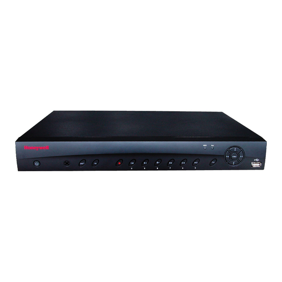
- Page 13 Figures | 13 Figures Figure 1-1 NVR Front Panel ......... . 27 Figure 1-2 NVR Back Panel .
- Page 14 Channel Settings Configuration Interface ......120 Figure 3-67 Abnormality Configuration Interface ....... . 122 www.honeywell.com/security...
- Page 15 Figure 4-1 Honeywell Config Tool Wizard ........132 Figure 4-2 User License Agreement Page .
- Page 16 Figure 5-64 Add Group Configuration Interface ....... . 202 www.honeywell.com/security...
- Page 17 Figures | 17 Figure 5-65 Modify Group Configuration Interface ....... 203 Figure 5-66 GUI Configuration Interface .
- Page 18 18 | Embedded Network Video Recorder User Guide www.honeywell.com/security...
- Page 19 Tables | 19 Tables Table 1-1 Embedded Network Video Recorder Features......26 Table 1-2 NVR Front Panel Components .
- Page 20 Specifications ..........227 www.honeywell.com/security...
-
Page 21: About This Document
About This Document This document introduces the Honeywell Embedded Network Video Recorder. It explains how to install and operate the Embedded Network Video Recorder. This document is intended for installers and users. Overview of Contents This document contains the following chapters and appendixes: •... -
Page 22: Related Documents
“enter” is used if you must type text and then press Enter Return key. Menu titles and other items you select Double-click Open from the File menu. Buttons you click to perform actions Click Exit to close the program. www.honeywell.com/security... - Page 23 | 23 Font What it represents Example Italic Placeholders: words that vary depending on the Enter your user name. situation Cross-reference to external source Refer to the Embedded NVR Quick Installation Guide. Cross-reference within document Chapter 2, Configuration. 800-18160 - A - 06/2014...
- Page 24 24 | Embedded Network Video Recorder User Guide www.honeywell.com/security...
-
Page 25: Introduction
Introduction This chapter covers: • An overview of the Embedded Network Video Recorder and its features. • An overview of the USB mouse. Overview of the Embedded NVR Bundle IP Cameras The Embedded Network Video Recorder is a high-performance network video recorder. It supports: •... -
Page 26: Features Of The Embedded Network Video Recorder
Internet connection. Backup • Supports backing up video, through the network, to a USB 2.0 device. The recorded files can be saved on the network storage server, on a peripheral USB 2.0 device, or to a burner, for example. www.honeywell.com/security... -
Page 27: Network Video Recorder Components
Introduction | 27 Table 1-1 Embedded Network Video Recorder Features Category Features Network Management • Supports NVR configuration and management through the Ethernet. • Supports device management through the Internet. Peripheral Equipment • Supports peripheral equipment management such as Management protocol setup and port connection. - Page 28 Left/Right • Shift the currently active control, then move left or right. • Playback mode: Click to control the playback bar. Enter ENTER • Confirm the current operation. • Go to the Default button. • Go to the Menu. www.honeywell.com/security...
- Page 29 Introduction | 29 Table 1-2 NVR Front Panel Components Component Name Icon Function USB 2.0 Port Connect to a USB 2.0 storage device, USB 2.0 mouse or CD/DVD burner. HDD Abnormal Lights to indicate an HDD error or when the Indication Light HDD capacity is below the specified threshold.
- Page 30 MIC OUT Audio Output Port Audio output port. It outputs the analog audio signal to devices such as an alarm. • Bi-directional communication output. • Audio output on a 1-window video monitor. • Audio output on a 1-window video playback. www.honeywell.com/security...
-
Page 31: Usb 2.0 Mouse Components And Functions
Introduction | 31 USB 2.0 Mouse Components and Functions Single-click the Left Mouse Button Table 1-4 Single-click Left Mouse Button Functions View menu content when you have selected a menu item. Modify a checkbox or motion detection status. Pop up a dropdown list. Input box: Select an input method for an input box. -
Page 32: Single-Click The Right Mouse Button
Number input mode: Increase or decrease the number’s value. Enable/disable a check box. Page up or down. Other Mouse Functions • Move the mouse to select the current control or move control. • Define a motion detection zone. • Define a privacy mask zone. www.honeywell.com/security... -
Page 33: Installation
Installation This chapter includes: • An overview of connections for alarms and bi-directional communication. • Instructions for HDD installation. • Network connections. Alarm Connection Connect the alarm input device to the alarm input port. Connect the alarm output device to the alarm output port. The NO and NC alarm output device can connect to the NO/C/NC port. -
Page 34: Bi-Directional Communication Connection
Connect the microphone or the pickup to the audio output port in the PC Connect the earphone or the sound box to the audio output port on your PC. Open web client and log in. Enable the desired channel in the web client’s live view monitor. Figure 2-1 for enabling bi-directional communication. www.honeywell.com/security... -
Page 35: Configuring To Hear Audio From The Pc
Installation | 35 Configuring to Hear Audio from the PC At the PC end, speak through the microphone or the pickup. Then you can get the audio from the speaker or earphone from the NVR. Figure 2-3 Configuring to Hear from the PC Hard Disk Drive Installation CAUTION Disconnect power if your NVR is connected to a power... -
Page 36: Figure 2-4 Removing The Nvr Cover
Loosening the Four Screws in the HDD Housing Align the HDD with the four holes in the bottom of the NVR housing. Figure 2-6 Placing the HDD Turn the NVR upside down, and then turn the screws to firmly attach the HDD to the NVR housing. www.honeywell.com/security... -
Page 37: Figure 2-7 Securing The Hdd To The Nvr Housing
Installation | 37 Figure 2-7 Securing the HDD to the NVR Housing Connect the HDD cable and power cable. Figure 2-8 Connecting the HDD and the Power Cable Replace the NVR cover. Figure 2-9 Replacing the NVR Cover Secure the NVR cover in place by turning the screws in the rear and side panels. Figure 2-10 Securing the NVR Cover 800-18160 - A - 06/2014... -
Page 38: Network Connection
38 | Embedded Network Video Recorder User Guide Network Connection Follow this diagram to connect your NVR to the network. Figure 2-11 Network Connections www.honeywell.com/security... -
Page 39: Nvr Configurations
NVR Configurations This chapter includes: • Logging into the NVR. • An overview of the NVR GUI, including live viewing, searching, and playing back. • Instructions on configuring the NVR. Logging In to Your NVR Before you can open the GUI for your NVR, you must do the following: Connect your NVR to a monitor. -
Page 40: Logging In
Icon Status Icon Status Recording status Video loss Motion detection Camera lock Logging In Left-click anywhere on the GUI. The System Login window appears. Figure 3-2 System Login Window Click to select the Password field. An electronic keyboard appears. www.honeywell.com/security... -
Page 41: Figure 3-3 Electronic Keyboard
NVR Configurations | 41 Figure 3-3 Electronic Keyboard Enter a password by using the mouse to select characters on the GUI keyboard. Click to switch between numbers, letters (uppercase/lowercase), and punctuation/symbols. The NVR has four default accounts. Table 3-2 Default Accounts Username Password Profile... -
Page 42: Live View
If you fail five times at logging within 30 minutes, you will be locked out of your account. Restart the NVR to unlock it. Live View Preview Control With the preview control, you can do the following: www.honeywell.com/security... -
Page 43: Preview Control Interface
NVR Configurations | 43 Preview Playback • While in the preview desktop, the NVR can play back the previous 5 to 60 minutes of recorded video from the current channel. Go to the Main Menu Setting General to configure the real-time playback settings. -
Page 44: Playback Control
Click to control a PTZ camera. Click to configure the video color settings. Click to search for recorded video. Main Menu After you have logged in to the NVR, the NVR’s main menu appears. www.honeywell.com/security... -
Page 45: Search And Playback
NVR Configurations | 45 Figure 3-7 Main Menu Search and Playback Click to open the Search interface. Figure 3-8 Search Interface 800-18160 - A - 06/2014... - Page 46 In the single-window playback mode, you can select one channel from the four available. In the 4-channel playback mode, you can select whatever four channels you require. The time bar changes when you modify the playback mode or the channel option. www.honeywell.com/security...
- Page 47 NVR Configurations | 47 Table 3-4 Search GUI Number Name Function File List Switch Button Double-click to view the snapshot/recorded file for the currently selected day. The file displays the recorded file for the first channel. The system can display up to 128 files at a time. Use ...
- Page 48 When in full-screen playback, you can switch to When Playing Back another channel either by using the drop-down list or by scrolling your mouse. This function is not available if there is no recorded file or if the NVR is conducting a Smart Search. www.honeywell.com/security...
-
Page 49: Figure 3-9 Card Number Search Interface
NVR Configurations | 49 Figure 3-9 Card Number Search Interface Table 3-5 Playback Controls Button Name Function Play/Pause There are three ways to begin playback: • Click , the play button. • Double-click a time on the time bar. •... -
Page 50: Information
50 | Embedded Network Video Recorder User Guide Information You can view the following information on the Information tab: • HDD INFO (hard disk information) • BPS (data stream statistics) • • Version • Online Users • Remote Device • Network Figure 3-10 Information Tab www.honeywell.com/security... -
Page 51: Hdd Information
NVR Configurations | 51 HDD Information Figure 3-11 HDD Information Tab This page shows the hard disk type, the total space, the free/available space, and the status of the HDD. You can have up to two HDDs. Table 3-6 HDD Drive Status Symbols Symbol Meaning The currently selected HDD is normal. -
Page 52: Bps
Click to view the HDD recording information, such as the file start Time time and file end time. View HDD Type and Click to view the HDD properties such as status, type, total space, Capacity free space, and S.M.A.R.T. Click BPS in the INFO tab to open the BPS interface. www.honeywell.com/security... -
Page 53: Log
NVR Configurations | 53 Figure 3-13 BPS Interface View the current video data stream (in KB/s) and the stored hard disk storage (MB/h). Click LOG in the INFO tab to open the LOG interface. The LOG tab displays system log information. Figure 3-14 Log Tab 800-18160 - A - 06/2014... -
Page 54: Version
Previous/Next to view other log information. For alarm events such as video loss, you can click the Playback button at the bottom right corner to play the alarm event-recorded video. Version Click VERSION in the INFO tab to open the VERSION interface. www.honeywell.com/security... -
Page 55: Online Users
NVR Configurations | 55 Figure 3-16 Version Tab On the Version tab, you can see the following information about your NVR: • The channel • Alarm in • Alarm out • System version • Build date • Web client software build number •... -
Page 56: Remote Device Information Tab
On this tab, you can view the channel status of the remote device, the connection log, etc. Channel Status: View the IP camera (IPC) status for the corresponding channel, such as motion detection, video loss, camera masking, and alarms. Figure 3-18 Channel/Device Status www.honeywell.com/security... -
Page 57: Network Information
NVR Configurations | 57 Connection Log: Search the IP camera log information for the corresponding channel. This includes the IP cameras that are online and offline. Figure 3-19 Connection Log Network Information Click NETWORK in the INFO tab to open the NETWORK interface. In the Network Test tab, you can test your network connection, and see the average delay and packet loss rate. -
Page 58: Figure 3-20 Network Test Tab
The NVR/system will save the packets to the specified path. The file name is Network adapter name+time. Opening the Packets Use software such as Wireshark to open the packets on the PC so that a professional engineer can solve the problem. www.honeywell.com/security... -
Page 59: Settings
NVR Configurations | 59 Network Load Click the NET LOAD on the Network Information configuration interface. View and follow the statistics for the device’s network adapter. Click to select a network adapter in the found network adapters table. Figure 3-21 Network Load Interface Statistics appear here. -
Page 60: Configuring The General Settings
60 | Embedded Network Video Recorder User Guide Figure 3-22 Setting Interface Note You need to have the proper rights to configure the Settings. Configuring the General Settings Click the GENERAL icon to open the General Settings interface. www.honeywell.com/security... -
Page 61: Figure 3-23 General Settings Interface
NVR Configurations | 61 Figure 3-23 General Settings Interface Table 3-8 General Settings Setting Description System time Configure the system time. Date format Select from three formats: YYYY-MM-DD, MM-DD-YYYY, or DD-MM-YYYY. Date separation Select from three formats: dot (.), hyphen (-), or slash (/). format Daylight Saving Configure the DST time and date. - Page 62 There is no year setup on the Holiday setting. This might be confusing for holidays that do not fall on the same date each year. For example, if you set a holiday for October 30, 2014, October 30th will be considered a holiday for every year after. www.honeywell.com/security...
-
Page 63: Configuring The Encoding Settings
NVR Configurations | 63 Table 3-8 General Settings Setting Description Mouse properties Click MouseSet to open the mouse setup interface. You can configure the mouse double-click speed. Click Default to restore the mouse settings to the default setup. Startup wizard If you check to enable the Startup wizard, then the next time the NVR restarts, it will open to the Startup wizard. -
Page 64: Figure 3-24 Encode Interface
Select from CBR and VBR. If you select VBR, then you can configure the video quality. Bit Rate Select from 4096, 6144, 8192, or customize the Bit Rate setting. If you choose Customize, you must enter a bit rate value. Audio/video Enable or disable the audio/video. www.honeywell.com/security... - Page 65 NVR Configurations | 65 Table 3-9 Encode Configurations Setting Description Overlay Click Overlay to open the Overlay interface. Cover area (privacy mask): Configure the privacy mask to block certain areas of the video. Drag the mouse to select the area. When in 1-channel mode, the NVR supports up to 4 privacy mask zones.
-
Page 66: Configuring The Schedule
All. Click OK twice (once in the Copy interface, once in the Encode interface) to save the settings and complete the setup. Configuring the Schedule Click the Schedule icon in the Setting interface to open the Schedule interface. www.honeywell.com/security... -
Page 67: Figure 3-25 Schedule Interface
NVR Configurations | 67 Figure 3-25 Schedule Interface Table 3-10 Schedule Configurations Parameter Function Channel Select a channel number. Select All for all channels. Week day Select a day of the week, or All. Pre-record The NVR has a buffer that allows it to "record" video that happens before an event occurs. -
Page 68: Configuring Rs232
Note If you select All, then the recording setup for all channels is the same, and then the Copy button disappears. Configuring RS232 Click the RS232 icon in the Setting interface to open the RS232 configuration interface. www.honeywell.com/security... - Page 69 NVR Configurations | 69 RS232 Configuration Interface Table 3-11 RS232 Configurations Parameter Function Function Select from six devices. Console: Use the COM or mini-end software to upgrade or debug the program. Control Keyboard: Use the special keyboard to control the NVR.
-
Page 70: Configuring The Network
Enter the default gateway. Note The system needs to check the validity of all IPv6 addresses. The IP address and the default gateway must be in the same IP section. The specified length of the subnet prefix must have the same string. www.honeywell.com/security... - Page 71 NVR Configurations | 71 Table 3-12 Network Configurations Parameter Function DHCP Used to automatically search for the IP address. When the DHCP function is enabled, you can not modify the IP address, Subnet mask, or Gateway. If you have not enabled DHCP, the IP address, Subnet mask, and Gateway are all 0 by default.
-
Page 72: Figure 3-28 Network Setting Configuration Interface
Configuring Network Settings Click NETWORK SETTING on the Network configuration interface. The Network Setting configuration interface opens. Figure 3-28 Network Setting Configuration Interface Click to enable a network setting configuration. Double-click to a configuration window for each network setting configuration. www.honeywell.com/security... -
Page 73: Figure 3-29 Ip Filter Configuration Interface
NVR Configurations | 73 Configuring the IP Filter Figure 3-29 IP Filter Configuration Interface You can add safe ID addresses which the NVR can safely access. You can add up to 64 IP addresses. Note The NVR needs to check the validity of all IPv6 addresses. 800-18160 - A - 06/2014... - Page 74 Configuring the NTP Setup Before you can use NTP, you must first install an SNTP server (such as Absolute Time Server) in your PC. In Windows XP OS, you can use command net start 232 time to boot up an NTP service. www.honeywell.com/security...
-
Page 75: Figure 3-30 Ntp Configuration Interface
NVR Configurations | 75 Figure 3-30 NTP Configuration Interface Table 3-14 NTP Configurations Parameter Function Host IP Enter your PC’s IP address. Port This NVR supports TCP transmission only. The default port value is 123. Update Period The minimum value is 1. The maximum value is 65535. (Units=minute) Time Zone Select the time zone here. -
Page 76: Figure 3-31 Multicast Configuration Interface
• Use for multiple cast broadcast in limited space You can use any IP address except for the IP addresses mentioned in Table 3-16. For example, you can use the following: • Multiple cast IP: 235.8.8.36 • Multiple cast port: 3666 www.honeywell.com/security... -
Page 77: Figure 3-32 Pppoe Configuration Interface
NVR Configurations | 77 After you have logged onto the web client, the web client can automatically get the multiple cast address, and add it to the multiple cast groups. You can enable the real-time monitor function to view the view. Configuring the PPPoE Settings Figure 3-32 PPPoE Configuration Interface... -
Page 78: Figure 3-33 Ddns Configuration Interface
DDNS function. Select the Honeywell DDNS server (which is free) to enable the DDNS function. Server IP This is the DDNS server IP address. Under Honeywell DDNS, the default server address is www.hennvr-ddns.com. Mode Select Auto or Manual. The default is Auto. If you select Manual, then you must enter a domain name. -
Page 79: Figure 3-34 Upnp Configuration Interface
NVR Configurations | 79 Note The NNDS type can include: Honeywell DDNS, CN99 DDNS, NO-IP DDNS, Quick DDNS, and Dyndns DDNS. All of these types of DDNS can be valid at the same time. Select which one you need. Note Do not register frequently. -
Page 80: Figure 3-35 Port Info Configuration Interface
Double-click the UPnP item in the list to configure it. A configuration window appears. Figure 3-35 Port Info Configuration Interface Configuring the WIFI Settings The Network Settings interface shows the WIFI connection status. The interface shows the current connection status and the IP address, if there is a connection. www.honeywell.com/security... -
Page 81: Figure 3-36 Wifi Connection Status
NVR Configurations | 81 Figure 3-36 WIFI Connection Status Double-click WIFI Setting to open the WIFI Setting interface. 800-18160 - A - 06/2014... -
Page 82: Figure 3-37 Wifi Setting Interface
Check to enable Auto Connect WIFI. The NVR automatically connects to the previous hotspot. Refresh Click to refresh the list of found hotspots. When the list is refreshed, the system automatically adds any previously configured information such as a password. www.honeywell.com/security... - Page 83 NVR Configurations | 83 Table 3-19 WIFI Setting Functions/Control Button/Control Description Disconnect Click to disconnect from the hotspot. Connection Click to connect to the hotspot. The NVR needs to turn off the current connection and then connect to a new hotspot, if you have selected a new one.
-
Page 84: Figure 3-38 Viewing Wifi Settings
User Name Enter the user name for logging in to the sender’s email box. Password Enter the login password here. Sender Enter the sender’s email address. Title Enter an email subject. You can use up to 32 letters or numbers. www.honeywell.com/security... -
Page 85: Figure 3-40 Configuring Ftp
NVR Configurations | 85 Table 3-20 Email Configurations Parameter Description Receiver Enter the receiver’s email address. You can enter up to 3 email addresses. SSL enable The NVR supports an SSL encryption box. Event Interval The interval for sending ranges from 0 to 3600 seconds. 0 means that there is no interval. -
Page 86: Figure 3-41 Testing The Ftp Setup
The system FTP server also supports uploading to multiple NVRs on one FTP server. You can Multiple NVRs create multiple folders under this FTP. onto an FTP Double-click FTP in the Network Setting configuration window. Server Figure 3-42 Network Setting Configuration Interface The FTP configuration interface appears. www.honeywell.com/security... -
Page 87: Figure 3-43 Ftp Configuration Interface
NVR Configurations | 87 Figure 3-43 FTP Configuration Interface Click to enable the FTP function. Enter an FTP server address, port, and remote directory. Table 3-21 FTP Configurations Parameter Description User Name The same user name that you used for logging in to the FTP. Password The same password that you used for logging in to the FTP. -
Page 88: Figure 3-44 Message Indication Ftp Connection Failure
Use the corresponding software tool (MIB Builder and MG-SOFT MIB Browser, plus two MIB files: BASE-SNMP-MIB, and NVR-SNMP-MIB) to connect to the NVR. The corresponding device configuration information appears after you have successfully connected. Double-click SNMP in the Network Setting configuration window. The SNMP configuration interface appears. www.honeywell.com/security... -
Page 89: Figure 3-45 Snmp Configuration Interface
NVR Configurations | 89 Figure 3-45 SNMP Configuration Interface Click to enable SNMP. Enter in the Trap Address field the IP address for the PC that is running the software. You can use the default settings for the other items. Compile the two MIB files. -
Page 90: Configuring Alarms
The server IP address can also be the domain. However, you need to register the domain name before you can run the proxy device server. Configuring Alarms Click the Alarms icon in the Setting interface to open the Alarms configuration interface. www.honeywell.com/security... -
Page 91: Figure 3-47 Alarms Configuration Interface
NVR Configurations | 91 Figure 3-47 Alarms Configuration Interface Table 3-22 Alarm Configurations Parameter Description Event Type Select from four types: Local input alarm: The alarm signal system detects from the alarm input port. Network input alarm: An alarm signal from the network. IPC external alarm: The on/off alarm signal from the camera, which activates the local NVR to receive the IP camera’s alarm if there is an alarm occurring at the camera. - Page 92 Days with an alarm period from 8:30 to 17:30, and then Configure a Monday alarm period for 7:10 to 18:00, the Monday alarm period overrides the Work Day alarm period. So on Mondays, the alarm period will be 7:10 to 18:00. www.honeywell.com/security...
- Page 93 NVR Configurations | 93 Table 3-22 Alarm Configurations Parameter Description Anti-dither Select an anti-dither time, from 5s to 600s. The anti-dither time starts when a second alarm is detected, and it determines what happens when a second alarm is detected. It determines if a second alarm will trigger another alarm action such as showing a screen alert, sending an email, starting a buzzer, flashing a light, activating a PTZ tour, taking a snapshot, or...
- Page 94 Set the alarm record and encoder parameters. • Go to Main Menu Setting Encode. Set the alarm input as the local alarm, and then select the recording channel. The NVR will record this channel when an alarm is detected. www.honeywell.com/security...
-
Page 95: Figure 3-48 Alarm Configuration Interface
NVR Configurations | 95 Note The system begins the alarm-triggered recording instead of motion detection-triggered recording if the local alarm and the motion detection event occur at the same time. Configuring PTZ Activation Set the video channel, speed dome protocol, and other parameters in the Pan/Tilt/Zoom configuration interface. -
Page 96: Configuring Detection Settings
Click OK to save the currently selected region. Right-click the mouse to exit the current interface. Click the Detect icon in the Setting interface to open the Detect configuration interface. Configuring Motion Detection Settings Select Motion Detection from the Event Type drop-down list. www.honeywell.com/security... -
Page 97: Figure 3-50 Detect Configuration Interface
NVR Configurations | 97 Figure 3-50 Detect Configuration Interface Table 3-23 Motion Detection Configurations Configuration Description Event Type Select the event detection type. Select from Motion Detection, Video Loss, or Camera Masking. Channel Select a channel. Enable Click to enable event detection. 800-18160 - A - 06/2014... - Page 98 3. Click ENTER on the NVR’s front panel to save the configuration, or click ESC to exit the area selection interface without saving the configuration. Sensitivity Select from 6 levels. Level 6 is the highest sensitivity. www.honeywell.com/security...
- Page 99 NVR Configurations | 99 Table 3-23 Motion Detection Configurations Configuration Description Period Configure when the event detection area is active. 1. Click Set. The Set configuration interface appears. 2. Select a day of the week, or Work Day or Free Day. Note If you select Work Day or Free Day, a Set button appears so you can configure which days are Work...
- Page 100 Display interface. If there is no alarm, the system implements the tour setup in the Display interface. Snapshot Click to enable the Snapshot function. A snapshot will be taken when an event occurs. Note You must click Save after configuring the settings to save them. www.honeywell.com/security...
- Page 101 NVR Configurations | 101 Note In the Detection interface, the copy-and-paste function is only valid for the same type of event detection. You can not copy a channel setup in video loss mode to camera masking mode. Configuring Video Loss Settings The Video Loss function allows you to be informed when video loss has occurred.
- Page 102 Latch When a video loss event is complete, the system automatically delays, for a specified time, the NVR from detecting new video loss detection events. www.honeywell.com/security...
- Page 103 NVR Configurations | 103 Table 3-24 Video Loss Detection Configurations Configuration Description Show message Configure the system to automatically pop up a message in the local view screen when an alarm occurs. Alarm upload Click to enable the system to upload the alarm signal to the network (including an alarm center and the web client).
-
Page 104: Figure 3-52 Camera Masking Configuration Interface
Figure 3-52 Camera Masking Configuration Interface Table 3-25 Camera Masking Detection Configurations Configuration Description Event Type Select the event detection type. Select from Motion Detection, Video Loss, or Camera Masking. Channel Select a channel. Enable Click to enable event detection. www.honeywell.com/security... - Page 105 NVR Configurations | 105 Table 3-25 Camera Masking Detection Configurations Configuration Description Period Configure when the event detection area is active. 1. Click Set. The Set configuration interface appears. 2. Select a day of the week, or Work Day or Free Day. Note If you select Work Day or Free Day, a Set button appears so you can configure which days are Work...
- Page 106 You must click Save after configuring the settings to save them. Note In the Detection interface, the copy-and-paste function is only valid for the same type of event detection. You can not copy a channel setup in video loss mode to camera masking mode. www.honeywell.com/security...
-
Page 107: Configuring Ptz Settings
NVR Configurations | 107 Configuring PTZ Settings Note All the operations here are based on the PELCOD protocol. For other protocols, there might be slight differences. Cable Connection Before You Begin Ensure that the following are connected: • Connect the camera’s RS485 port to the NVR’s 485 port. •... -
Page 108: Figure 3-53 Pan/Tilt/Zoom Configuration Interface - Local
Check Select from Odd, Even, or None. The default is None. Note The above configurations are available only if you choose Local for the PTZ type. If you choose Remote, you can only select the channel. See Figure 3-54. www.honeywell.com/security... -
Page 109: Figure 3-54 Ptz Configuration Interface - Remote
NVR Configurations | 109 Figure 3-54 PTZ Configuration Interface - Remote Note You must click Save after configuring the settings to save them. Controlling PTZ Cameras Go to the single window viewing mode. Open the PTZ camera controller by: • Right-clicking in the window. -
Page 110: Configuring Display Settings
110 | Embedded Network Video Recorder User Guide Table 3-27 PTZ Controls Control Function Function Shortcut Function Function Shortcut Zoom Wide Focus Near Iris Close Open Configuring Display Settings Click the DISPLAY icon in the Setting interface to open the Display configuration interface. www.honeywell.com/security... -
Page 111: Figure 3-56 Display Configuration Interface
NVR Configurations | 111 Figure 3-56 Display Configuration Interface Table 3-28 Display Configurations Configuration Description Transparency Adjust the transparency of the GUI overlay. Select from 128 to 255. Channel Name Customize the channel name. You can enter up to 31 characters. -
Page 112: Configuring Default Settings
In the Default interface, you can click to select what parameters are returned to their default settings. Choose from: • Select All • General • Remote Device • Schedule • RS232 • Network • Alarm • Detect • Pan/Tilt/Zoom • Display • Channel Name www.honeywell.com/security... -
Page 113: Connecting To And Configuring The Remote Devices/Cameras
8Mbps. It supports 100/120 @ 1080p. The delay time for each channel is below 500 ms. Your NVR supports IP cameras from many popular manufacturers such as Honeywell, Sony, Hitachi, Dynacolor, Axis, Samsung, Arecont, Dahua, and Onvif. Just enter the camera’s URL address, user name, and password to log in to the camera. -
Page 114: Configuring The Remote Device/Camera
Switch Settings Configuration Interface Enter values for the IP Address, Subnet Mask, and Gateway. Click OK to save these settings. Configuring the Remote Device/Camera Click the REMOTE DEVICE icon in the Main Menu to open the Remote Device configuration interface. www.honeywell.com/security... -
Page 115: Figure 3-59 Remote Device Configuration Interface
NVR Configurations | 115 Figure 3-59 Remote Device Configuration Interface Table 3-29 Remote Device Configurations Configuration Description IP Search Click to search for an IP address. Click to connect to the selected, found IP device (camera), and add it to the Added device list. -
Page 116: Figure 3-60 Manual Add Configuration Interface
If there is no IP camera connected, the GUI shows Figure 3-61. Figure 3-61 Short-cut to Remote Device Configuration Interface Click the + in the center of the Preview interface for the channel which is not connected to an IP camera. The Remote Device configuration interface appears. www.honeywell.com/security... -
Page 117: Advanced Configurations
NVR Configurations | 117 Figure 3-62 Remote Device Configuration Interface Advanced Configurations Click the ADVANCED icon in the Main Menu to open the ADVANCED configuration interface. The ADVANCED configuration interface appears. Figure 3-63 Advanced Configuration Interface 800-18160 - A - 06/2014... -
Page 118: Configuring Hdd Management
118 | Embedded Network Video Recorder User Guide Configuring HDD Management In the HDD MANAGE configuration window, you manage the Hard Disk Drive and view its current HDD type, status, capacity, and record time. Figure 3-64 HDD MANAGE Configuration Interface www.honeywell.com/security... - Page 119 NVR Configurations | 119 When the HDD is working properly, you see an O. When an HDD error has occurred, you see an X. Table 3-30 HDD MANAGE Configurations Configuration Description Alarm Set Click Alarm Set. The Alarm Set configuration interface appears.
-
Page 120: Figure 3-65 Hdd Setting Configuration Interface
Configure the HDDs for the main stream, the extra stream, and for snapshots as well. The main and extra stream configurations for one channel can be saved to different groups. Channel: Displays the actual channel number for the current NVR. www.honeywell.com/security... -
Page 121: Configuring Abnormality Settings
NVR Configurations | 121 HDD Group: The SN of the HDD Group management. See Configuring HDD Group Settings on page 119. Note Ensure that you have set the HDD Group for each channel. If you fail to set the HDD Group for a channel, then you will not be able to save the current setup. Note When you change the HDD Group settings, the system will save the recorded video and snapshots, then reboot. -
Page 122: Figure 3-67 Abnormality Configuration Interface
Go to Main Menu Setting Network Email to configure the email settings. See Configuring the Email Settings on page Buzzer Click to enable the Buzzer function. When an alarm occurs, the buzzer beeps. www.honeywell.com/security... -
Page 123: Configuring Alarm Output
NVR Configurations | 123 Configuring Alarm Output Click ALARM OUTPUT in the ADVANCED configuration interface. The ALARM OUTPUT configuration interface appears. Figure 3-68 ALARM OUTPUT Configuration Interface Click to make your selections, and then click OK to save the changes. Configuring Manual Recording Settings Note You must have proper rights to configure the Recording settings. -
Page 124: Configuring Account Settings
In the ACCOUNT configuration interface, you can do the following: • Add a new user • Modify a user • Add a group • Modify a group • Modify a password Click ACCOUNT in the ADVANCED configuration interface. The ACCOUNT configuration interface appears. www.honeywell.com/security... -
Page 125: Figure 3-70 Account Configuration Interface
NVR Configurations | 125 Figure 3-70 ACCOUNT Configuration Interface Account Naming Conventions The maximum length for the account name and user name is 6 bytes. There cannot be a space at the beginning or the end of the name string. But there can be a space in the middle. -
Page 126: Figure 3-71 Add Group Configuration Interface
The procedures for adding a user and modifying a user are similar. The Add User configuration interface is shown in this example. Click Add User or Modify User in the ACCOUNT configuration interface. The Add User or Modify User configuration interface opens. www.honeywell.com/security... - Page 127 NVR Configurations | 127 Figure 3-72 Add User Configuration Interface Enter a User name, a Password (twice), and Memo information, if required. Click Reuseable to enable the Reuseable function. See Reusable Function on page 125. Click to enable privileges for this user. TIP! We recommend that general user account rights are less than administrator account user rights.
-
Page 128: Configuring Automatic Maintenance Settings
Figure 3-74 AUTO MAINTAIN Configuration Interface Select from the drop-down lists a day and time for automatically rebooting the system. Select from Never, Every day, Every Sunday, Every Monday, Every Tuesday, Every Wednesday, Every Thursday, Every Friday, or Every Saturday. www.honeywell.com/security... -
Page 129: Configuring Backup
NVR Configurations | 129 Select from the drop-down lists when the system automatically deletes the old files. Select either Never or Customized. If you select Customized, then you can enter how many days until the system next automatically deletes the old files. Click OK to save the new settings. -
Page 130: Figure 3-76 Shutdown Dialog Box
If you shut down the device, a process bar appears for your reference. The system waits for 3 seconds and then shuts down. You can not cancel the shut down sequence after it has begun. Note You might need to enter your password to shut down the NVR. www.honeywell.com/security... -
Page 131: Honeywell Configuration Tool
Starting the Honeywell Configuration Tool You must install the Honeywell Configuration Tool before you can use it to discover IP devices. Installing the Honeywell Configuration Tool Insert the Software CD that came with your NVR into your PC. Navigate to and double-click Honeywell Config Tool to install the configuration tool software. -
Page 132: Figure 4-1 Honeywell Config Tool Wizard
132 | Embedded Network Video Recorder User Guide Figure 4-1 Honeywell Config Tool Wizard Click Next to begin the installation. The User License Agreement page appears. Figure 4-2 User License Agreement Page Click to select I agree, and then click Install to install the software. -
Page 133: Opening The Honeywell Configuration Tool, Searching For Devices, And Opening A Web Client
Installation is Complete Page Click Enjoy Now to open and use the Config Tool. Opening the Honeywell Configuration Tool, Searching for Devices, and Opening a Web Client In the Config Tool, you will find the IP addresses for the IP devices (NVRs and IP cameras). -
Page 134: Upgrading A Single Device (Ip Camera Or Nvr)
For the following, examples of upgrading an IP camera are shown. The procedures for upgrading an NVR are similar. Open the ConfigTool software. Figure 4-5 ConfigTool Login Select from the list the device you want to upgrade. Click Login to log in to the device. www.honeywell.com/security... -
Page 135: Figure 4-6 Device Upgrade Login Interface
Honeywell Configuration Tool | 135 If you do not select a device before clicking Login, you will get a Connection Note Error message. Figure 4-6 Device Upgrade Login Interface Click OK. The Config Upgrade interface appears. Figure 4-7 Config Upgrade Interface Click OpenFile to select the upgrade file, and then click Upgrade to begin the upgrade. -
Page 136: Figure 4-8 Device Offline Message
136 | Embedded Network Video Recorder User Guide Figure 4-8 Device Offline Message Click OK to close the Device Offline warning message, and to return to the Upgrade interface. Figure 4-9 Upgrade Interface Log into the device again. www.honeywell.com/security... -
Page 137: Upgrading The Ip Devices (Batch Upgrade)
Honeywell Configuration Tool | 137 If you do not select a device before clicking Login, you will get a Connection Note Error. Upgrading the IP Devices (Batch Upgrade) Note For the following, examples of upgrading an IP camera are shown. The procedures for upgrading an NVR are similar. -
Page 138: Figure 4-11 Upgrade Interface
Click Open to find and select the upgrade file. The Open interface appears. Figure 4-12 Open Interface Select the upgrade firmware, and then click Open or double-click the file to open it. The Open interface closes and you return to the Upgrade interface. www.honeywell.com/security... -
Page 139: Figure 4-13 Upgrade Interface
Honeywell Configuration Tool | 139 Figure 4-13 Upgrade Interface Click to select the devices you want to upgrade. Their row turns blue when selected. Click Upgrade to begin the batch upgrade. A message appears in the Upgrade State fields for each selected IP camera to show the batch upgrade progress. -
Page 140: Modifying The Ip Address
140 | Embedded Network Video Recorder User Guide A message appears to show that the batch upgrade procedure is successful. Figure 4-15 Batch Upgrade Successful Message Modifying the IP Address Open the ConfigTool software if it is not already open. Figure 4-16 ConfigTool Login www.honeywell.com/security... -
Page 141: Figure 4-17 Selecting Net In The Configtool
Honeywell Configuration Tool | 141 Select from the list the device you want to modify. Click Login to log in to the device. Figure 4-17 Selecting Net in the ConfigTool Click Net to open the Net tab. Enter the new IP Address, and the corresponding Subnet Mask and Gateway. - Page 142 142 | Embedded Network Video Recorder User Guide www.honeywell.com/security...
-
Page 143: Web Operation
Web Operation This chapter includes: • A description of the NVR web client. • Descriptions about setting up and operating the NVR web client. Preparing to Use the Device Web Client PC Requirements Table 5-1 PC Requirements Component Minimum Requirement Processor Quad core System memory (RAM) -
Page 144: Before You Log In
The current NVR supports various browsers such as Apple Safari, Mozilla Firefox, and Google Chrome. The NVR supports only 1-channel monitoring on an Apple PC. Logging In Open a Web browser window. Note These instructions were created using IE. You can use Internet Explorer (IE), Safari, Chrome, or FireFox. www.honeywell.com/security... -
Page 145: Figure 5-1 Ie Window
Web Operation | 145 Figure 5-1 IE Window Enter the IP address Enter the NVR IP address in the address field. For example, if your NVR’s IP address is 192.168.1.108, then enter http://192.168.1.108 in the address field. A message pops up asking if you want to install webrec.cab control. Click Yes to install webrec.cab control. -
Page 146: Figure 5-2 Configuring The Activex Controls
146 | Embedded Network Video Recorder User Guide Figure 5-2 Configuring the ActiveX Controls When installation is successful, the login interface appears. Figure 5-3 Login Interface Enter your username (default: admin) and password (default: 1234). www.honeywell.com/security... -
Page 147: Lan Mode
Web Operation | 147 Note For security, we recommend that you modify your password on your first log in. LAN Mode The LAN main window, which is divided into 9 main sections. Figure 5-4 LAN Mode Main Window Section 1: Function Buttons Figure 5-5 LAN Main Window Function Buttons 800-18160 - A - 06/2014... -
Page 148: Section 2: Monitor Channels
Section 4: Start Talk Button Figure 5-8 Start Talk Button Click to enable communication. Click in the control panel on the right to select the bi-directional communication mode. There are four options for the communication mode: DEFAULT, G711a, G711u, and PCM. www.honeywell.com/security... -
Page 149: Section 5: Instant Record Button
Web Operation | 149 After you enable bi-directional communication, the system will not encode the audio data from that one channel. See Bi-Directional Communication Connection on page 34 for the audio connections. Section 5: Instant Record Button Figure 5-9 Instant Record Button Click Instant Record, and the button turns blue. -
Page 150: Section 9: Viewer Configuration Controls
Click to switch to switch to four channel viewing. Real-Time Monitoring Left-click a channel name in Section 2, the Monitors Channel section, to select that channel for viewing. The video window shows statistics about the video. Figure 5-11 Live View Video Window www.honeywell.com/security... -
Page 151: Controlling Ptz Camera
Web Operation | 151 Table 5-3 Live View Video Window Controls Table 5-4 Live View Video Window Controls Control Description Display Device Shows the following information about the video: Information • IP address • Channel number • Bit rate • Decoding mode: Select either M for Main stream or S for sub stream. -
Page 152: Figure 5-12 Ptz Controls
3. Click Add Preset button, and the new preset is added to the tour. 4. Repeat for all the presets you want to include in the tour. To remove a preset from the tour, click the Delete preset button. www.honeywell.com/security... -
Page 153: Configuring Image/Alarm Out Settings
Web Operation | 153 Table 5-5 PTZ Setup Configurations Control Description Pattern 1. Select Pattern from the drop-down list. 2. Enter a pattern value, and then click Start to begin PTZ movement. PTZ movement includes zooming in, focusing, adjusting the iris, and changing the camera field of view. 3. -
Page 154: Configuring Alarm Output
Click to open the Alarm Out configuration interface. Figure 5-14 Alarm Out Configuration Interface Disable/enable the alarm signal for the corresponding port. Playing Back Recorded Video Click the Playback tab at the top of the Main window. The Playback interface appears. Figure 5-15 Playback Interface www.honeywell.com/security... -
Page 155: Figure 5-16 List Of Recorded Video Clips
Web Operation | 155 Select a recording type, recording date, window display mode, and channel name to select video for playback. Click File List, and the system displays a list of recorded video clips that match the search criteria from step Figure 5-16 List of Recorded Video Clips... -
Page 156: Downloading Video
The Download button becomes the Stop button, and it indicates the downloading progress (in a percentage). Go to your default Saved Path file to view the downloaded files. See Configuring the Save Path on page 164. Loading More Click More in Figure 5-18, and the Download by File/Download by Time interfaces appear. www.honeywell.com/security... -
Page 157: Enabling And Disabling Alarms
Web Operation | 157 Figure 5-19 Download by File/Download by Time Interfaces In this window, you can search for recordings or snapshots. Select the channel, recording type, and the recording time. Enabling and Disabling Alarms Click the Alarm tab at the top of the Main window. The Alarm configuration interface appears. Note For information about configuring alarms, see Configuring Alarms on page... -
Page 158: Figure 5-20 Alarm Configuration Interface
Alarm button on the Main interface when there is an alarm. Alarm Sound Click to enable the Alarm Sound. Then the system triggers an alarm sound when an Alarm Sound alarm occurs. You can choose the sound. Sound Path Select the sound file. www.honeywell.com/security... -
Page 159: Configuring Settings
Web Operation | 159 Configuring Settings Click the Set tab at the top of the Main window. The Set configuration interface appears. In the Set configuration interface, you can configure the following: • Remote settings • Audio and video encoding settings •... -
Page 160: Figure 5-21 Remotely Adding A Device Configuration Window
Added device list to open a configuration window to change the corresponding channel setup. Delete Click to delete the remote connection for the corresponding channel. Connection Status indicates that the connection was successful. indicates that the connection was not successful. www.honeywell.com/security... -
Page 161: Remotely Configuring Video And Audio
5-22. 2. Select a channel from the drop-down list. Only disconnected channels are shown. Note The NVR supports cameras from Honeywell, Panasonic, Sony, Dynacolor, Samsung, AXIS, Arecont, Dahua, and cameras with ONVIF-standard protocol. Note If you do not enter an IP address, the system uses the default IP address 192.168.0.0, and the system does... -
Page 162: Figure 5-23 Video&Audio Configuration Interface
This is not available in VBR mode. Reference Bit Rate The recommended bit rate value based on your settings for the resolution and the frame rate. Configuring Snapshot Settings Click the Snapshot tab on the Video&Audio configuration interface to open the Snapshot configuration interface. www.honeywell.com/security... -
Page 163: Figure 5-24 Snapshot Configuration Interface
Web Operation | 163 Figure 5-24 Snapshot Configuration Interface Table 5-10 Snapshot Configurations Configuration Description Channel Select a channel from the drop-down list. Mode There are two modes: Timing (schedule) and Trigger. Timing: The snapshot function is valid during the specified time period. -
Page 164: Figure 5-25 Video Overlay Configuration Interface
Use the mouse to drag the time display to the desired position. View the time display on the live web client video or the playback video. Configuring the Save Path Click Path in the Video&Audio configuration interface to open the Path configuration interface. www.honeywell.com/security... -
Page 165: Configuring The Channel Name
Web Operation | 165 Figure 5-26 Path Configuration Interface Click Browse to configure a new save path for snapshots or recorded video. The default locations are C:\PictureDownload and C:\RecordDownload. Click Save to save any changes. Configuring the Channel Name Click Channel Name in the Video&Audio configuration interface to open the Channel Name configuration interface. -
Page 166: Figure 5-28 Tcp/Ip Configuration Interface
For the IPv6 version IP address, the Preferred DNS and Alternate DNS shall be no more the 128 digits. They also can not be left blank. LAN Download Enable this function so that the system can process the downloaded data first. The download speed is 1.5X or 2.0X of the normal speed. www.honeywell.com/security... -
Page 167: Configuring The Network Connection
Web Operation | 167 Configuring the Network Connection Click Connection in the Network configuration interface to open the Connection configuration interface. Figure 5-29 Connection Configuration Interface Table 5-13 Network Connection Configurations Configuration Description Max Connection The maximum Web connection for the same NVR. The value ranges from 1 to 120. -
Page 168: Configuring Cdma/Gprs For 3G
Double-click the name of a wireless device to connect to it. Note Click Refresh to update the list of wireless network information. Configuring CDMA/GPRS for 3G Click 3G in the Network configuration interface to open the 3G configuration interface. Click the CDMA/GPRS tab to open the CDMA/GPRS configuration interface. www.honeywell.com/security... -
Page 169: Configuring The Mobile Setup For 3G
Web Operation | 169 Figure 5-31 CDMA/GPRS Configuration Interface Table 5-14 CDMA/GPRS Configurations Configuration Description WLAN Type Select a 3G network type to distinguish this 3G module from different ISPs. Choose from WCDMA, CDMA1x, for example. APN & Dial No. APN and the Dial No. -
Page 170: Configuring Pppoe
Click Save to save the changes. Reboot the device to activate these changes. After rebooting, the device should connect to the Internet through the PPPoE connection. The IP address is found in the WAN from the IP address column. www.honeywell.com/security... -
Page 171: Configuring Ddns
Email Address Server email address. Honeywell DDNS The Honeywell DDNS function works with a special DDNS server and special Professional Surveillance Software (PSS). Click DDNS in the Network configuration interface to open the PPPoE configuration interface. 800-18160 - A - 06/2014... -
Page 172: Figure 5-34 Ddns Configuration Interface
172 | Embedded Network Video Recorder User Guide Figure 5-34 DDNS Configuration Interface Operation Before you can use Honeywell DDNS, you need to enable this service and configure the proper server address, port value, and domain name. Table 5-16 DDNS Configurations... -
Page 173: Configuring The Ip Filter
Web Operation | 173 Configuring the IP Filter Click IP Filter in the Network configuration interface to open the IP Filter configuration interface. Figure 5-35 IP Filter Configuration Interface Click to enable Trusted Sites, and only the listed IP addresses can access the current NVR. -
Page 174: Figure 5-36 Email Configuration Interface
Enter an email subject. You can use up to 32 letters or numbers. Attachment Click to enable so that a snapshot can be attached to the email. Receiver Enter the receiver’s email address. You can enter up to 3 email boxes. www.honeywell.com/security... -
Page 175: Configuring Upnp
Web Operation | 175 Table 5-17 Email Configurations Parameter Description Interval The interval for sending ranges from 0 to 3600 seconds. 0 means that there is no interval. Note The system will not send an email immediately when the alarm occurs. When an alarm, motion detection, or video abnormality triggers an email, the system sends out the email according to the interval that is specified here. -
Page 176: Configuring Snmp
SNMP allows the communication between the network management work station software and the proxy of the managed device. It is reserved for a third party developer. Click SNMP in the Network configuration interface to open the SNMP configuration interface. www.honeywell.com/security... -
Page 177: Configuring Multicast
Web Operation | 177 Figure 5-38 SNMP Configuration Interface Table 5-18 SNMP Configurations Configuration Description SNMP Port The listening port of the proxy program of the NVR. It is a UDP port, not a TCP port. This value ranges from 1 to 65535. The default is 161. -
Page 178: Configuring Auto Registration Settings
In network service, the device supports IPv4 server addresses or domains. Click Auto Register in the Network configuration interface to open the Auto Register configuration interface. Figure 5-40 Auto Register Configuration Interface Configuring Events Click the Event arrow to expand the Event selection tree. www.honeywell.com/security... -
Page 179: Configuring Detection Settings
Web Operation | 179 Configuring Detection Settings Configuring for Motion Detection You can configure the system to generate a motion detection alarm when the minimum amount of motion (as defined by you) is detected in the video. Click Detect in the Event configuration interface to open the Detect configuration interface. Figure 5-41 Detect Configuration Interface 800-18160 - A - 06/2014... - Page 180 3. Configure a time range for when the event detection area is active, then click the check box to select that time range. 4. Click Save. Sensitivity Select from six levels of sensitivity. The higher the number, the higher the sensitivity. www.honeywell.com/security...
- Page 181 Web Operation | 181 Table 5-19 Motion Detection Configurations Configuration Description Region 1. Select a motion detection type. 2. Click Set. The Motion Detection Set configuration interface appears. 3. Select the event detection area by left-clicking and dragging the mouse. There are 396 (PAL) or 330 (NTSC) small zones.
- Page 182 2. Click to select a channel, or All, then click Save. Snapshot Click to enable the Snapshot function. A snapshot will be taken when an alarm occurs. 1. Click Set to open the Snapshot Configuration interface. 2. Click to select a channel, or All, then click Save. www.honeywell.com/security...
-
Page 183: Configuring For Video Loss Detection
Web Operation | 183 Table 5-19 Motion Detection Configurations Configuration Description Show Message Click to enable a pop-up message on your local host PC screen to let you know an alarm has occurred. Send Email The system can send an email when an alarm is detected. When you have enabled the Snapshot function, the system can also send an image attached to the email. -
Page 184: Configuring For Camera Masking
You can configure local and network alarms. Click Alarm in the Event configuration interface to open the Alarm configuration interface. Configuring Local Alarms Click Local Alarm in the Alarm configuration interface to open the Local Alarm configuration interface. www.honeywell.com/security... -
Page 185: Figure 5-44 Local Alarm Configuration Interface
Web Operation | 185 Figure 5-44 Local Alarm Configuration Interface Table 5-20 Local Alarm Configurations Configuration Description Enable Click to enable local alarms. Select a channel from the drop-down list. Period Define a period during which local alarms are active. 1. - Page 186 1. Click Setup to select a tour channel. The system begins a 1-window or multiple-window tour display showing the channels you’ve set to record when an alarm occurs. 2. Click to select a channel, or All, then click Save. www.honeywell.com/security...
-
Page 187: Configuring Net Alarms
Web Operation | 187 Table 5-20 Local Alarm Configurations Configuration Description Snapshot Click to enable the Snapshot function. A snapshot will be taken when an alarm occurs. 1. Click Set to open the Snapshot Configuration interface. 2. Click to select a channel, or All, then click Save. Show Message Click to enable a pop-up message on your local host PC screen to let you know an alarm has occurred. -
Page 188: Configuring External Alarms
Configuring Local Alarms on page 184 for more information. Configuring for No Signal The system can generate an alarm if the network camera goes offline. Click No Signal in the Alarm configuration interface to open the No Signal configuration interface. www.honeywell.com/security... -
Page 189: Configuring For Abnormalities
Web Operation | 189 Figure 5-47 No Signal Configuration Interface The configuration for No Signal Alarms is very similar to the configuration for Local Alarms. Please see Configuring Local Alarms on page 184 for more information. Configuring for Abnormalities Click Abnormality in the Event configuration interface to open the Abnormality configuration interface. -
Page 190: Configuring Storage
Click the Storage arrow to expand the Storage selection tree. Configuring Schedules for Storage You can add or remove schedules for recording. There are four recording modes: General (auto), Motion Detect, Alarm, and MD&Alarm. Click Schedule in the Storage selection tree to open the Schedule configuration interface. www.honeywell.com/security... -
Page 191: Figure 5-49 Schedule Configuration Interface
Web Operation | 191 Figure 5-49 Schedule Configuration Interface The schedules are color-coded by type: • Green: General recording/snapshot. • Yellow: Motion detection recording/snapshot. • Red: Alarm recording/snapshot. • Blue: MD&Alarm recording/snapshot. Click Set. The Set configuration interface opens. Figure 5-50 Set Configuration Interface 800-18160 - A - 06/2014... -
Page 192: Configuring Local Storage For Schedules
HDD), and formatting. Configuring the HDD Group Settings Click HDD Setting in the Schedule configuration interface to open the HDD Setting configuration interface. Figure 5-52 HDD Setting Configuration Interface Select the HDD group in which you want to save the recording. www.honeywell.com/security... -
Page 193: Configuring Recording Settings
Web Operation | 193 Configuring Recording Settings Click Record in the Schedule configuration interface to open the Record configuration interface. Figure 5-53 Record Configuration Interface for Storage Settings Table 5-23 Recording Configurations for Storage Configuration Description Channel View the channel number. The number displayed here is the maximum number of channels for your NVR. -
Page 194: Configuring The Channel For Schedules
Extra Stream Configuration Interface Select an HDD Group from the drop-down menu, then click Save. Configuring the Image Storage Channel You can select the corresponding HDD group for saving snapshots. Click the Image Storage tab to open the Image Storage configuration interface. www.honeywell.com/security... -
Page 195: Configuring Settings
Web Operation | 195 Figure 5-56 Image Storage Configuration Interface Select an HDD Group from the drop-down menu, then click Save. Configuring Settings In the Settings configuration interface, you can configure: • General settings such as the device’s name, number, language, video standard, date and time settings, and holidays. -
Page 196: General Settings
Select the recording duration. Select from 1 to 120 minutes. The default is 60 minutes. Date & Time Settings Click the Date & Time tab in the General settings configuration interface to open the Date & Time configuration interface. www.honeywell.com/security... -
Page 197: Holiday Settings
Web Operation | 197 Figure 5-58 Date & Time Configuration Interface Table 5-25 Date & Time Configurations Configuration Description Date Format Select the date format from the drop-down list. Time Format Select from either 24 hour or 12 hour. Date Separator Select from a period (.), a hyphen (-), or a slash (/). -
Page 198: Configuring Account Settings
Users can belong to only one group. Click Account in the General settings configuration interface to open the Account settings configuration interface. www.honeywell.com/security... -
Page 199: Configuring User Settings
Web Operation | 199 Figure 5-60 Account Settings Configuration Interface Configuring User Settings There are four default users: • admin • 888888 • 666666 • a hidden user All except default user 666666 have administrator rights. User 666666 has only monitor rights. The hidden default user is for internal use only, and can not be deleted. -
Page 200: Figure 5-61 Add User Configuration Interface
Enter a Username and a Password. Re-enter the Password to confirm it. Select a Group. Select System, Playback, and Real-Time Monitor privileges. Click Save to save these new settings. Modifying a User Click under Modify to open the Modify User configuration interface. www.honeywell.com/security... -
Page 201: Configuring Group Settings
Web Operation | 201 Figure 5-62 Modify User Configuration Interface Change the settings, then click Save. Modifying a Password Click Modify Password in the Modify User configuration interface. Enter the old Password, then enter the new Password twice. Click OK to save the new password. Note Passwords can have up to 6 characters, numbers only. -
Page 202: Figure 5-63 Group Configuration Interface
Click Add Group in the Group Account configuration interface. Figure 5-64 Add Group Configuration Interface Enter a Group name. Select System, Playback, and Real-time Monitor privileges. Click Save to save these new settings. Modifying a Group Click under Modify to open the Modify Group configuration interface. www.honeywell.com/security... -
Page 203: Configuring Display Settings
Web Operation | 203 Figure 5-65 Modify Group Configuration Interface Modify the Group privileges, then click Save to save the changes. Configuring Display Settings Click Display in the General settings configuration interface to open the GUI settings configuration interface. 800-18160 - A - 06/2014... -
Page 204: Enabling And Disabling Alarm Out Settings
Image Enhance Check to enable Image Enhance, to optimize the preview video. Enabling and Disabling Alarm Out Settings Click Alarm Out in the General settings configuration interface to open the Alarm Out settings configuration interface. www.honeywell.com/security... -
Page 205: Returning To Default Settings
Web Operation | 205 Figure 5-67 Alarm Out Configuration Interface Click to enable alarm types for each or all of the alarm outputs. Returning to Default Settings Click Default in the General settings configuration interface to open the Default settings interface. -
Page 206: Configuring Automatic Maintenance Settings
Figure 5-70 Auto Maintain Configuration Interface Select when the NVR automatically reboots, both day and time. Select when the NVR automatically deletes old files. Click Save to save the new settings. Note Click Manual Reboot to manually reboot the NVR. www.honeywell.com/security... -
Page 207: Configuring Pan/Tilt/Zoom Settings
Web Operation | 207 Configuring Pan/Tilt/Zoom Settings Before Configuring PTZ Settings Please ensure that the following connections are correct before configuring the PTZ settings. • Ensure that the PTZ and decoder connections are correct, and that the decoder address setup is correct. See Configuring PTZ Settings on page 107. -
Page 208: Configuring Preview Control Settings
If you select View 1, you have to select a Preview Channel. If you select View 4, you have to select all channels for previewing. Configuring System Information Click the Info tab on the Main Menu to open the Info configuration interface. www.honeywell.com/security... -
Page 209: Viewing The Version
Web Operation | 209 Viewing the Version Click the arrow next to System to expand the System menu tree. Click Version to open the Version configuration interface. Figure 5-74 Version Configuration Interface Here you can view the recording channel, the alarm input/output information, the software version, and the release date. -
Page 210: Viewing The Online Users
Click to clear the found log files. Note You can not clear by log file. Backup Click to backup the currently selected files to the selected PC. Viewing the Online Users Click Online User in the System menu to open the Online User interface. www.honeywell.com/security... -
Page 211: Logging Out
Web Operation | 211 Figure 5-76 Online User Configuration Interface You can view what users are currently online. Logging Out Click the Logout tab in the Main Menu. The NVR returns to the Login interface. Figure 5-77 Login Interface 800-18160 - A - 06/2014... - Page 212 212 | Embedded Network Video Recorder User Guide www.honeywell.com/security...
-
Page 213: Appendix A Troubleshooting
Troubleshooting Prior to calling Honeywell technical support, refer to the following topics for possible solutions to problems with your ONVIF camera. To contact the Honeywell Video Systems technical support team, call 1-800-323-4576 (North America only) or send an e-mail to https://www.honeywellsystems.com/ss/techsupp/index.html. -
Page 214: Problem: The Nvr Cannot Detect The Hard Disk
Problem: Motion detection does not work Possible solutions: • Check that the period setup is correct. [Motion detection active period?] See Configuring the Schedule on page • Check the motion detection zone setup. • Check that the motion sensitivity level is not too low. www.honeywell.com/security... -
Page 215: Problem: You Can Not Log Into The Nvr Or Web Client
Troubleshooting | 215 Problem: You can not log into the NVR or web client Possible solutions: • Upgrade to Windows 2000 SP4 from Windows 98 or Windows ME if you are using them on your system. Or you can install a client-end software of a lower version. Note The NVR is not compatible with Windows VISTA. -
Page 216: Problem: You Have Forgotten The Local Menu Operation Password Or Network Password
Increase the bandwidth or reduce the number of channels for viewing. • Ensure that your PC meets the minimum requirements: Table A-1 PC Requirements Component Minimum Requirement Processor Quad core System memory (RAM) 2G pr higher Non-integrated video 256M or higher card www.honeywell.com/security... -
Page 217: Appendix B Daily Maintenance
Daily Maintenance • Please use a brush to clean the board, socket connector and the chassis regularly. • Carefully ground the NVR to protect from audio/video disturbances. Keep the NVR away from static voltage or induced voltage. • Please unplug the power cable when you remove the audio/video signal cable, RS232, or RS485 cable. - Page 218 218 | Embedded Network Video Recorder User Guide www.honeywell.com/security...
-
Page 219: Appendix C Compatible Sata Hdd
Compatible SATA HDD Table C-1 Compatible SATA HDD Manufacturer Series Model Capacity Port Mode Seagate Seagate SV35.1 ST3250824SV 250G SATA Seagate Seagate SV35.1 ST3500641SV 500G SATA Seagate Seagate SV35.2 ST3250820SV 250G SATA Seagate Seagate SV35.2 ST3320620SV 320G SATA Seagate Seagate SV35.2 ST3500630SV 500G SATA... - Page 220 SATA Seagate Seagate Constellation ES.2 ST33000651NS SATA Seagate Seagate Constellation ES.2 ST32000646NS SATA Seagate Seagate Constellation ES.2 ST33000652NS SATA Seagate Seagate Constellation ES.2 ST32000647NS SATA Western Digital Cariar SE WD3200JD 320G SATA Western Digital Cariar SE WD3000JD 300G SATA www.honeywell.com/security...
- Page 221 Compatible SATA HDD | 221 Table C-1 Compatible SATA HDD Manufacturer Series Model Capacity Port Mode Western Digital Cariar SE WD2500JS 250G SATA Western Digital Cariar SE 16 WD7500KS 750G SATA Western Digital Cariar SE 16 WD5000KS 500G SATA Western Digital Cariar SE 16 WD4000KD 400G...
- Page 222 Hitachi Hitachi CinemaStar™ 5K500 HCP725050GLA 500G SATA Hitachi Hitachi CinemaStar™ HCT721050SLA 500G SATA 7K1000.B Hitachi Hitachi CinemaStar™ HCT721075SLA 750G SATA 7K1000.B Hitachi Hitachi CinemaStar™ HCT721010SLA SATA 7K1000.B Maxtor DiamondMax 20 STM3320820AS 320G SATA Maxtor DiamondMax 20 STM3250820AS 250G SATA www.honeywell.com/security...
-
Page 223: Appendix D Compatible Usb 2.0 Devices
Compatible USB 2.0 Devices Table D-1 Compatible USB 2.0 Devices Manufacturer Model Capacity Sandisk Cruzer Micro 512M Sandisk Cruzer Micro Sandisk Cruzer Micro Sandisk Cruzer Freedom 256M Sandisk Cruzer Freedom 512M Sandisk Cruzer Freedom Sandisk Cruzer Freedom Kingston Data Traveler II Kingston Data Traveler II Kingston... - Page 224 224 | Embedded Network Video Recorder User Guide Table D-1 Compatible USB 2.0 Devices Manufacturer Model Capacity Netac U210 512M Netac U210 Netac U210 Teclast Ti Cool 128M Teclast Ti Cool 256M Teclast Ti Cool 512M Teclast Ti Cool Teclast Ti Cool www.honeywell.com/security...
-
Page 225: Appendix E Compatible Monitors
Compatible Monitors Table E-1 Compatible Monitors Manufacturer Model Screen Size BenQ (LCD) ET-0007-TA 19-inch (wide screen) Dell (LCD) E178FPc 17-inch BenQ (LCD) Q7T4 17-inch BenQ (LCD) Q7T3 17-inch Lenovo (LCD) LXB-L17C 17-inch Samsung (LCD) 225bw 22-inch (wide screen) Lenovo (CRT) LXB-FD17069HB 17-inch Lenovo (CRT) - Page 226 226 | Embedded Network Video Recorder User Guide Table E-1 Compatible Monitors Manufacturer Model Screen Size Philips (LCD) 220CW9 23-inch Philips (LCD) 220BW9 24-inch Philips (LCD) 220EW9 25-inch www.honeywell.com/security...
-
Page 227: Appendix F Specifications
Specifications Table F-1 Specifications System Main Processor Dual-core embedded processor Operating System Embedded LINUX Video IP Camera Inputs 4 channels Two-way Talking 1 channel input; 1 channel output; BNC Display Interface 1 HDMI, 1 VGA Resolution 1920 x 1080; 1280 x 1024; 1280 x 720; 1024 x 768 Display Split Camera title;... - Page 228 12 V DC; 5 A Power Supply (PoE) 48 V DC; 1.04 A Power Consumption 20 W (without HDD) (NVR) Power Consumption Maximum 15 W each (PoE) Environmental Operating Temperature 14° F to 131°F (-10°C to 55°C) Humidity 10% to 90% www.honeywell.com/security...
- Page 229 Specifications | 229 Table F-1 Specifications Physical Dimensions 14.8 x 11.2 x 2.0 inches (375 x 285 x 50 mm) Weight (without HDD) 5.07 pounds (2.3 kg) 800-18160 - A - 06/2014...
- Page 230 230 | Embedded Network Video Recorder User Guide www.honeywell.com/security...
-
Page 231: Index
| 231 Index Numerics alarm in, number of alarm out 1080p motion detection 12 V DC port number of 1280x960 alarm output configuration 232 debug COM alarms 3D intelligent positioning key abnormalities 3G configurations 168, abnormality alarm upload WLAN type alarm in channel 40 V DC port alarm out... - Page 232 PTZ activation back panel components recording channel back up recording delay files settings backup snapshot settings file name tour www.honeywell.com/security...
- Page 233 | 233 cameras abnormality buzzer PTZ control abnormality email remotely adding abnormality event type cameras supported abnormality latch capacity abnormality message abnormality settings card number search accounts cautions administrative scoped addresses CDMA1X alarm buzzer CDMS for 3G alarm delay configurations alarm emails channel alarm event type...
- Page 234 99, event detection sensitivity motion detection PTZ activation 100, event type motion detection recording channel external alarms motion detection recording delay frame rate motion detection region frequency of snapshots motion detection relay FTP file length motion detection schedule www.honeywell.com/security...
- Page 235 | 235 motion detection sensitivity RS232 PTZ matrix motion detection settings RS232 stop bits motion detection snapshot RS232 transparent COM motion detection snapshot settings RTSP port 71, motion detection tour schedule channel motion detection tours schedule channels mouse properties schedule day MTU for network adaptor schedule extra stream channel multicast...
- Page 236 DDNS server IP address WIFI display resolution WIFI autoconnect domain name WIFI settings gateway configuring email event interval Honeywell DDNS server address 78, configuring GPRS for 3G HTTP port 71, configuring IPC time sync HTTPS port connecting maximum network connections alarms...
- Page 237 | 237 details attachments information, log configuring event interval configuring health email detection settings 96, configuring password device configuring port connection mode configuring receiver’s address configuring sender name configuring server SMTP number 62, configuring SMTP device control configuring SSL encryption device number configuring title device search...
- Page 238 62, time test recording settings four-channel window total space frame rate type remotely configuring view recording time free day view type and capacity front panel components HDMI port www.honeywell.com/security...
- Page 239 125, IP multicast group address hidden user default password IPv6 holiday period settings 62, Honeywell config tool keyboard Honeywell DDNS 78, 79, 171, host IP HTTP port configuration default 71, download HTTPS port LAN mode configuration function buttons...
- Page 240 TCP port latch settings test message settings transfer mode messages UDP port period 99, video quality PTZ activation network abnormal indicator PTZ activation settings network alarms recorded file color network connection recording channel configurations www.honeywell.com/security...
- Page 241 | 241 configuring maximum connections no disk error 122, requirements no signal time no space error period normally closed video loss settings normally open playback button port channel selection port default file list server interface setup mode updated period playing recorded video 149, upgrade period NTSC 62, ports...
- Page 242 64, real-time default backup display monitoring remotely configuring playback control restarting the NVR receive rate restore to default settings record operation reusable function www.honeywell.com/security...
- Page 243 | 243 right-click menu type router send rate LAN IP sender port mapping configuring email RS232 sensitivity baud rate event detection configuration serial number configuring the function server IP console control DDNS data bit default service data bits settings 44, 61, 62, default baud rate HDD group default data bit...
- Page 244 MAC address remote configurations configuring email preferred DNS remote configurations default version remote configurations email TCP/IP mode user naming conventions remote configurations user rules TCP/IP settings user settings remote configurations username test 6666666 email 888888 HDD recording location admin time DDNS 78, www.honeywell.com/security...
- Page 245 | 245 hidden default configuration hidden default user configuring remotely PPPoE privacy mask users time display configuration adding 126, video, downloading maximum connection view recording time modifying 126, viewer configuration controls viewing network MAC address volume button version system vertical synchronization VGA port video IP address...
- Page 246 246 | Embedded Network Video Recorder User Guide www.honeywell.com/security...
- Page 248 Document 800-18160 – Rev A – 06/2014 © 2014 Honeywell International Inc. All rights reserved. No part of this publication may be reproduced by any means without written permission from Honeywell. The information in this publication is believed to be accurate in all respects. However, Honeywell cannot assume responsibility for any consequences resulting from the use thereof.
Need help?
Do you have a question about the HEN04111 and is the answer not in the manual?
Questions and answers
I have a Honeywell HEN 16161 that has stop working, Can I replace it with the HEN 04111 and use my cameras that was connected to the 16161