Table of Contents
Advertisement
Advertisement
Table of Contents

Related Manuals for Honeywell VARIODYN D1


Summary of Contents for Honeywell VARIODYN D1
- Page 1 ® VARIODYN D1 System Installation Instruction 798663.GB0 05.2019...
- Page 2 The use of this documentation does not grant you a licence or any other right to use the name, logo and/or the label. This documentation is subject to the copyright of Honeywell. The content must not be copied, published, modified, distributed, transmitted, sold or changed without the express prior written permission of Honeywell.
-
Page 3: Table Of Contents
® Installation Instruction VARIODYN D1 System Table of contents General /Application ............................... 4 Responsibility of the Operator ..........................5 Related Documents ..............................5 Standards and Directives ............................... 6 Approvals .................................. 7 Planning and configuration ............................9 System Overview ..............................9 ®... -
Page 4: General /Application
® Installation Instruction VARIODYN D1 System General /Application In line with the applicable standards, the following systems must all consist of components that satisfy the standards of the EN 54 series: a sound system for emergency purposes (SEP), as per EN 50849; a voice alarm system (VAS), as per DIN VDE 0833-4, and, in Austria, a sound system for emergency purposes (SEP), as per TRVB (technical fire prevention guideline) 158 S. -
Page 5: Responsibility Of The Operator
® Installation Instruction VARIODYN D1 System Responsibility of the Operator In addition to the standard-compliant design, a stipulation of the minimum requirements and functions between the operator of the system and the responsible authorities is required for the construction and operation of a VAS system. -
Page 6: Standards And Directives
® Installation Instruction VARIODYN D1 System Standards and Directives An emergency audio warning system (AWS) or a voice alarm system (VAS) as defined by the DIN VDE 0833-4 and TRVB 158 S standards must consist of components that meet the standards of the DIN EN 54 series. It must be ensured that these components interact together in line with the function. -
Page 7: Approvals
® Installation Instruction VARIODYN D1 System Approvals Specification EN 54-4 : 1997 / A1 : 2002 / A2 : 2006 EN 54-16 : 2008 and EN 54-17 : 2006 Declaration of Performance DoP-20997130701 DoP-00376130701 DoP-00405140414 • ® The DoP numbers apply to VARIODYN D1 voice alarm systems including all components. - Page 8 ® Installation Instruction VARIODYN D1 System The current and valid versions of each of these standards, regulations and ordinances must be observed during the planning and installation as well as during the operation of an emergency intercom system or voice alarm system, including connection to a fire alarm system (FAS).
-
Page 9: Planning And Configuration
® Installation Instruction VARIODYN D1 System Planning and configuration The planning and configuration information below offers a quick overview of the proper use as well as the technical ® capabilities of the VARIODYN D1 System. The specifications in the technical planning documents as well as the applicable standards, national regulations and local requirements must always be complied with in the installation. -
Page 10: Redundancy Of The Variodyn D1 System
® Installation Instruction VARIODYN D1 System ® Redundancy of the VARIODYN D1 System ® Alternatively, the VARIODYN D1 System can also have a redundant structure. The devices listed in the diagram are required for this purpose. essernet ® ® Fig. 2: Redundancy of the VARIODYN D1 System ... -
Page 11: System Requirements
® Installation Instruction VARIODYN D1 System System requirements Number without Number from Components protocol 11 protocol 11 DOM / SCU / ETCS Amplifier channels 1000 1600 Multiple amplifiers PA-Server PC-Callstation • With a DAL bus, the cables are run in a star arrangement and with Ethernet in a tree arrangement (from device to device) •... -
Page 12: Cable Types And Specifications
® Installation Instruction VARIODYN D1 System Cable Types and Specifications ® The cable types listed are required for installation of the VARIODYN D1 System and must be used accordingly. DAL-Bus (Digital Audio Link) Devices, such as digital call stations (DCS) digital fire brigade call stations (DCSF) and universal interface modules (UIM) are connected to the digital output module (DOM) via the DAL bus. - Page 13 ® Installation Instruction VARIODYN D1 System Ethernet (100 Mbit) Maximum cable length = 90 m between two devices. A longer cable length can be realised using standard LAN repeaters (option). PIN8 PIN1 Assignment TX + TX - RX + Not assigned Not assigned RX - Not assigned...
- Page 14 ® Installation Instruction VARIODYN D1 System 3.4.1 System cables (overview) The following system cables are required for directly connecting the devices in the installation cabinet: Name Part No. ® Patch cable CAT5, 1 m, yellow, (ETH) VARIODYN 583486A ® Patch cable CAT5, 2 m, yellow, (ETH) VARIODYN 583487A ®...
- Page 15 ® Installation Instruction VARIODYN D1 System 3.4.2 Specification loudspeaker cables The following cable cross-sections (mm²) must be used for loudspeaker loop, depending on the power and cable length: 100 W 200 W 300 W 400 W 500 W Power Length 100 m 0.75 0.75...
-
Page 16: Mounting
® Installation Instruction VARIODYN D1 System Mounting Requirements for the installation site and installation surface The floor type cabinet installation with voice alarm systems may only be installed in dry, clean, and adequately lit areas with restricted access acc. to DIN EN 60721-3-3. If several voice alarm system components are to be installed in an enclosed floor type cabinet, it is necessary, for example, to consider the maximum load capacity (kg/m²) of the floor (e.g. -
Page 17: Overview Of The Individual System Components For Rack Mounting
® Installation Instruction VARIODYN D1 System Overview of the Individual System Components for Rack Mounting ® Fig. 6: VARIODYN system components (example) Abbreviation Description Part No. Universal-Interface-Module 583331.21 Main-Switch-Unit 583371.21 System-Communication-Unit 583381.22, 583381.31 View-Control-Module 583315 Digital-Output-Module 583361.22, 583362.22 580221.41, 580222.41, 580231, 580232, 580242, 580243, Power Amplifier 580248, 580248.11, 580249.11, 580262 FB 798663.GB0 / 05.19... -
Page 18: Floor Type Cabinet / Rack-Mounting (Part No. 5849Xx)
® Installation Instruction VARIODYN D1 System Floor type cabinet / Rack-mounting (Part No. 5849xx) Conventional cabinet systems offer good access from the front and back or have a pivot frame which can be used to swivel the installed electronics out of the cabinet. Optional components can be mounted on C profile rails, for example. - Page 19 ® Installation Instruction VARIODYN D1 System Example drawer rail or PA1 = 2 x 200 W installation bracket below the amplifier PA2 = 2 x 200 W total weight ca. 40 kg Fig. 8: Example installation of devices with installation bracket (Example) Device Weight Device...
-
Page 20: Installation
® Installation Instruction VARIODYN D1 System Installation Cable paths and installation Only use the cable entries provided by the factory. Use separate cable entries and cable glands for the power supply and signal lines. All connected voltage and signal lines must be secured with suitable fastening material, e.g. -
Page 21: Wiring Of The Loudspeaker
® Installation Instruction VARIODYN D1 System Wiring of the loudspeaker 5.1.1 Spur The End of line module (EOL-Part No. 583496) for terminating the loudspeaker circuits for standardised system monitoring if more than 20 loudspeakers are connected per line. The EOL is connected at the end of the line, after the last loudspeaker. - Page 22 ® Installation Instruction VARIODYN D1 System 5.1.2 Loop Loudspeaker connection using loop technology with standardised cable monitoring enables redundant cabling including Loop Isolator Modules (LIM e. g. Part No. 583342). The LIM is installed in the ring loop and isolates operational areas from areas where a short-circuit has occurred. This ensures complete loudspeaker functionality on the ring loop at all times.
- Page 23 ® Installation Instruction VARIODYN D1 System Features • ® Approved in accordance with EN 54-17 (included in the EN 54-16 approval of the VARIODYN D1 System) • Up to 4 rings per DOM4-8 or DOM4-24 • Up to 500 W power per loop •...
- Page 24 ® Installation Instruction VARIODYN D1 System Wiring example with 6 Fire section (FS) Fig. 17: Loop technology in place of A/B cabling (example) • Do not route outbound and inbound ring conductors in the same cable or the same conduit. •...
-
Page 25: Devices
® Installation Instruction VARIODYN D1 System Devices Digital-Output-Module (DOM) ® The DOM (Part No. 583361.22 or 583362.22) is the central control element of the VARIODYN D1 System. Components such as the call stations, the double final amplifiers, and also the loudspeakers are connected to a DOM. - Page 26 ® Installation Instruction VARIODYN D1 System 110 … 230 V AC – Rated voltage A power supply cable is included in the delivery. Observe local standards and guidelines prior to operation. Alternatively, the connection can take place via the main switch unit (MSU). See chapter 6.3.
- Page 27 ® Installation Instruction VARIODYN D1 System AVC1 to AVC4 (inputs for the automatic volume control AVC) Up to 2 sensor microphones each can be connected to the AVC inputs. The AVC1 AVC2 AVC3 AVC4 automatic volume control (AVC) is regulated via the sensor microphones. Audio equipment may also be connected.
- Page 28 ® Installation Instruction VARIODYN D1 System IN REP / PA (100 V AF signal input) These terminals are designed with touch protection. • 4x power amplifier inputs (PA) • 4x power amplifier backup inputs (REP) The AF signals modulated by the power amplifier are connected to these connection terminals of the DOM and run from there internally to the individual loudspeaker circuits (use only system cables).
- Page 29 ® Installation Instruction VARIODYN D1 System CH1 to CH4 SPK OUT (loudspeaker circuits) Connections for the loudspeaker circuits The DOM4-8 and DOM4-24 modules are equipped with four independent audio outputs in order to control four amplifier channels. Each audio output •...
- Page 30 ® Installation Instruction VARIODYN D1 System Monitor button (on the front panel) The monitor button can be used to listen in to the audio outputs and inputs on the DOM. Pressing the button repeatedly will run through the individual listening points. The current listening point is indicated by flashing (green) of the respective LED.
- Page 31 ® Installation Instruction VARIODYN D1 System 6.1.2 Specification - DOM Audio output Output type Electronically symmetrical Nominal level 0 dBu Max. output level + 6 dBu Frequency range 20 Hz … 20 kHz Max. variance from linear frequency ± 1 dB in the frequency range Distortion factor at nominal level 0.03 % @ 1 kHz Max.
- Page 32 ® Installation Instruction VARIODYN D1 System 6.1.3 DOM Flex Applications for 2XD- and 4XD-Amplifier ® Using DOM Flex applications, a DOM or VARIODYN D1 Comprio can operate flexibly with the optimal number ® of amplifier channels. All applications are compatible with existing components such as a DOM, VARIODYN Comprio, and amplifiers that comply with EN 54-16 certification.
- Page 33 ® Installation Instruction VARIODYN D1 System 6.1.4 Application 2-12 Application 2–12 operates with a DOM with two amplifier channels. Each amplifier channel supplies 12 loudspeaker lines. When using a four-channel amplifier, an extra DOM and the application 2–12 can use the remaining two channels.
- Page 34 ® Installation Instruction VARIODYN D1 System 6.1.5 Application 1-18 Application 1–18 operates with a DOM with two amplifier channels. The first amplifier channel supplies 18 loudspeaker lines. The second channel supplies six loudspeaker lines and can be used with amplifiers 4XD125B and 4XD250B for backup.
- Page 35 ® Installation Instruction VARIODYN D1 System 6.1.6 Application 1-24 – Variant 1 Application 1–24 – variant 1, operates with three DOM, each with an amplifier channel. The amplifier channel supplies all the loudspeaker lines of the DOM = 66 zones per amplifier + backup for all three DOM. •...
- Page 36 ® Installation Instruction VARIODYN D1 System 6.1.7 Application 1-24 – Variant 2 Application 1–24 – variant 2, operates with four DOM, each with an amplifier channel. The amplifier channel supplies all the loudspeaker lines of the DOM – a total of 96 zones. No backup. ...
- Page 37 ® Installation Instruction VARIODYN D1 System 6.1.8 Application 1-24 – Variant 3 supplies all the loudspeaker lines of the DOM, separated according to A and B ≙ 96 AB zones. No backup. Application 1–24 – variant 3, operates with four DOM, each with an amplifier channel. The amplifier channel ...
- Page 38 ® Installation Instruction VARIODYN D1 System 6.1.9 Application 1-24 – Variant 4 Application 1–24 – variant 4, operates with two DOM with amplifiers 2XD250 or 2XD400. Fig. 31: Overview application 1-24 – Variant 3 DOM 1 DOM 1 DOM 2 DOM 2...
-
Page 39: View-Control-Module (Vcm)
® Installation Instruction VARIODYN D1 System View-Control-Module (VCM) The View Control Module (Part No. 583351) allows the standard-compliant display of collective messages as well as operation via the five integrated buttons. For VAS according to EN 54-16, at least one VCM required. For every additional room with VAS installation cabinets, a separate VCM must be used. - Page 40 ® Installation Instruction VARIODYN D1 System View-Control-Module (VCM) UIM and DOM connection Connection of the VCM The collective messages are passed on to the VCM via the control contacts of the UIM and displayed on the VCM. Use the prefabricated cable for the CONNECTION UIM connection.
- Page 41 ® Installation Instruction VARIODYN D1 System Connection of the DOM Monitoring of the life sign signals takes place via the control LIVE SIGNAL contacts of DOM 1. Use cable type I-Y (St) Y 2 x 2 x 0.8 mm and the enclosed two-pin plug to make the connection.
-
Page 42: Main Switch Unit (Msu)
® Installation Instruction VARIODYN D1 System Main Switch Unit (MSU) ® The Main Switch Unit (Part No. 583371.21) is used to individually safeguard the power supply of all VARIODYN D1 components that are installed in a floor type cabinet. Up to three components can be connected to a MSU. Each of the three connections can accept a current of max. - Page 43 ® Installation Instruction VARIODYN D1 System L1-L3, N, PE Connection of the 230 V AC rated voltage L1 / L2 / L3 and N / PE. Danger – Electric shock! L1 L2 L3 N Assembly and installation work may only be performed when the system is de-energised (voltage free).
- Page 44 ® Installation Instruction VARIODYN D1 System Connection Main-Switch-Unit (MSU) DOM and PA 1. Connect 230 V AC rated voltage / emergency power supply to the terminal block of the MSU. The protective earthing conductor (PE) and neutral conductor (N) must always be connected. 2.
- Page 45 ® Installation Instruction VARIODYN D1 System 6.3.1 Protection against a break in the neutral wire The neutral conductor monitoring module (Part No. 584970) should be used to protect against a break in the neutral conductor occurring. This module is connected upstream with the MSU contactor (Part No. 584971) and enables the safe and immediate all-pole interruption of the power supply in the event of: •...
- Page 46 ® Installation Instruction VARIODYN D1 System 6.3.2 Specification - MSU Thermal fuse protection Rated current 18 A Indicator lamp 230 V AC Service life 10,000 switching cycles Deactivation Single-pole Withstand voltage Test voltage 3000 V AC >100 MΩ (500 V DC) Insulation resistance Switching capacity Icn 150 A...
-
Page 47: Universal Interface Module (Uim)
® Installation Instruction VARIODYN D1 System Universal Interface Module (UIM) ® The Universal Interface Module (Part No. 583331.21) serves as the interface module of the VARIODYN System for a connection between two analogue audio inputs, two analogue audio outputs and 48 control contacts. The UIM is connected to the digital output module (DOM) via the DAL bus and is also supplied with the required operating power via this connection. - Page 48 ® Installation Instruction VARIODYN D1 System Control contacts (inputs/outputs) The 48 control contacts (digital I/O) can be used for controlling voice alarm system components or for connection to other systems, such as a fire alarm control panel. The function of the input or output can be individually programmed in the configuration for each control contact.
- Page 49 ® Installation Instruction VARIODYN D1 System Audio outputs The two analogue potential-free audio outputs are arranged symmetrically on the XLR sockets and asymmetrically on the CINCH sockets. The audio signal is available on the L + R CINCH sockets. ...
- Page 50 ® Installation Instruction VARIODYN D1 System Connecting universal interface module (UIM) DOM 1. Use a patch cable CAT5 blue to connect the DAL connection of the DOM and the DAL connection of the UIM. 2. If external control inputs or outputs are present, wire them to the terminals of the UIM . 3.
- Page 51 ® Installation Instruction VARIODYN D1 System 6.4.1 Specification - UIM Audio inputs Nominal level 0 dBu Max. level + 6 dBu Frequency range 20 Hz … 22 kHz Signal-to-noise ratio > 95 dB Distortion factor at nominal level < 0.05 % Audio outputs Nominal level 0 dBu...
-
Page 52: System Communication Unit (Scu)
® Installation Instruction VARIODYN D1 System System Communication Unit (SCU) ® The System Communication Unit is used as a digital audio memory for the VARIODYN D1. Voice information and music are saved in the SCU and can be loaded later using the buttons of the call station, for example. The storage of alarms and messages for evacuation measures takes place according to EN 50849 in a non-volatile electronic memory element with a capacity of approximately 120 minutes. - Page 53 ® Installation Instruction VARIODYN D1 System 6.5.2 System Communication Unit SCU (Part No. 583381.31) Fig. 45: Rear view SCU (Part No. 583381.31) Device fuse 5 AT/250 V IEC power socket 230 V AC incl. device fuse 1.6 AT ...
- Page 54 ® Installation Instruction VARIODYN D1 System 6.5.3 System Communication Unit (SCU) DOM connection Before connecting the SCU to a VARIODYN ® D1 network, an IP address (network address) must be configured via web-interface. Factory setting IP address of SCU: 192.168.1.136. Further Information about IP address refer to commissioning instructions (Part No.
- Page 55 ® Installation Instruction VARIODYN D1 System 6.5.4 Lithium Battery A 3 V lithium battery (type CR2032) is integrated into the SCU (Part No. 583381.31) unit to protect the customer data. In order to ensure the protection over the long term, this battery should be replaced after no more than five years, such as during regular maintenance.
-
Page 56: Power Amplifiers (Pa)
® Installation Instruction VARIODYN D1 System Power Amplifiers (PA) The power amplifier modules are each equipped with two or four amplifier channels. These are controlled and ® monitored by the VARIODYN D1 modules DOM4-8 or DOM4-24. • ® Correct functioning of the VARIODYN D1 System is only ensured with a power amplifier and a suitably configured DOM. -
Page 57: Power Amplifier 2Xh-Series
® Installation Instruction VARIODYN D1 System Power amplifier 2XH-Series The 2XH series power amplifiers provide two independent amplifier channels. For additional information refer to product catalogue. Fig. 48: Front view power amplifier (Example 2XH500) Additional information on LED indicators refer to operating instruction (Part No. 798662.GB0). Fig. - Page 58 ® Installation Instruction VARIODYN D1 System 7.1.1 DIP switches 2XH series Factory setting 1 2 3 CH 1/2 Configuration of the LED signalling for indicating the audio signals as of -20 dB or as of -6 dB. Separate, individual settings are possible for both channels 1 (CH 1) and 2 (CH 2). DC FAULT ON ...
-
Page 59: Power Amplifier 2Xd-Series
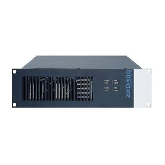
® Installation Instruction VARIODYN D1 System Power amplifier 2XD-Series The 2XD series power amplifiers provide two independent amplifier channels (double final amplifiers). For additional information refer to product catalogue. Fig. 50: Front view power amplifier (Example 2XD250) Additional information on LED indicators refer to operating instruction (Part No. 798662.GB0). Fig. - Page 60 ® Installation Instruction VARIODYN D1 System 7.2.1 DIP-Switch 2XD-Series The housing of the amplifier must be opened to configure the DIP switch. Disconnect the system beforehand! Fig. 52: Position of the DIP-Switch SW1 Danger – Electric shock! Assembly and installation work may only be performed when the system is de-energised (voltage free). ESD / EMC preventive measures Before handling electronic modules, always take suitable precautions to prevent static electricity.
-
Page 61: Connect - 2Xh And 2Xd-Series
® Installation Instruction VARIODYN D1 System Connect - 2XH and 2XD-series 1. Connect the power amplifier to the switched power supply of the MSU. If an MSU is not present, connect the power amplifier directly to the power supply / emergency power supply. 2. - Page 62 ® Installation Instruction VARIODYN D1 System 7.3.1 Specification - 2XH and 2XD-Series Type 2XH500 2XD250 / 2XD400 Mains voltage 230 V AC, +10% / -15% Frequency range 50 … 60 Hz Emergency power supply 24 V DC Rated current @ 230 V AC 5,7 A 1 A / 1,6 A Rated current @ 24 V DC...
-
Page 63: Power Amplifiers 4Xd-Series
® Installation Instruction VARIODYN D1 System Power Amplifiers 4XD-Series The power amplifiers provide four independent amplifier channels (double final amplifiers). The described functions depend on the amplifiers required and/or used for the specific building. For additional information refer to product catalog. 7.4.1 Power Amplifier 4XD125B Fig. - Page 64 ® Installation Instruction VARIODYN D1 System 7.4.2 DIP switch 4XD125B Before commissioning, the DIP switch should be set to the desired function according to the table below. Here, OFF corresponds to the upper position and ON to the lower one. •...
- Page 65 ® Installation Instruction VARIODYN D1 System 7.4.3 Power Amplifier 4XD250B The four-channel amplifier 4XD250B was specifically developed for use in the VARIODYN ® D1 voice alarm system and has four independent individual amplifiers, each with 250 W output. With an installation height of just two HUs, the amplifier is suitable for rack mounting and has a battery charging device to supply the voice alarm system with emergency power which is capable of charging batteries up to 105 Ah in compliance with standards.
- Page 66 ® Installation Instruction VARIODYN D1 System 7.4.4 DIP switch 4XD250B Before commissioning, the DIP switch should be set to the desired function according to the table below. Here, OFF corresponds to the upper position and ON to the lower one. •...
- Page 67 ® Installation Instruction VARIODYN D1 System 7.4.5 Power Amplifier 4XD300 / 4XD500 The four-channel amplifier 4XD300/4XD500 was developed specifically for use in the VARIODYN ® D1 voice alarm system and has four independent individual amplifiers, each with 300 W/500 W output and galvanically-isolated 100 V direct outputs, symmetrical inputs, inrush current limiting and soft starter.
- Page 68 ® Installation Instruction VARIODYN D1 System 7.4.6 DIP switch 4XD300/4XD500 Before commissioning, the DIP switch should be set to the desired function according to the table below. Here, ON corresponds to the upper position and OFF to the lower one. •...
-
Page 69: Power Amplifier 4Xv Series
® Installation Instruction VARIODYN D1 System Power Amplifier 4XV series The power amplifiers provide four independent amplifier channels (double final amplifiers). The described functions depend on the amplifiers required and/or used for the specific building. For more information, see the product group catalogue. -
Page 70: Connect - 4Xd And 4Xv-Series
® Installation Instruction VARIODYN D1 System Connect - 4XD and 4XV-series 7.6.1 Connection DOM and Power Amplifier 1. Connect the DOM with the redundant power supply of the power amplifier. 2. Connect the PA output of the control unit and the D1 LINK CONTROL INTERFACE socket of the power amplifier with the green input cable DOM-Amplifier ... - Page 71 ® Installation Instruction VARIODYN D1 System 7.6.2 Specification - 4XD and 4XV-Series Type 4XD125B 4XD250B 4XD300 4XD500 4XV300 4XV500 Mains voltage 230 V AC, +10% / -5% Frequency range 50 … 60 Hz Emergency 21,5 V DC … 28,5 V DC 24 V DC power supply Rated current...
-
Page 72: Using Backup Amplifiers
® Installation Instruction VARIODYN D1 System Using backup amplifiers 7.7.1 Series 2XHx00 and 2XDxx0 One DOM and one backup amplifier: (with 2 channels): • Backup for 6 DOMs, each using one power amplifier • Backup for 12 DOMs, each using two power amplifiers The output power of the backup amplifier must be equal to or higher than that of the largest power amplifier. - Page 73 ® Installation Instruction VARIODYN D1 System 7.7.2 Series 4XD125B and 4XD250B One DOM and one backup channel: • This channel can act as backup for the other three channels • Additional backup for 5 DOMs, each using one four-channel amplifier (with main aplifiers) ...
- Page 74 ® Installation Instruction VARIODYN D1 System 7.7.3 Series 4XDx00 and 4XVx00 One DOM and one backup amplifier: • Backup for 6 DOMs, each using one four-channel amplifier (with main aplifiers) With a four-channel backup amplifier incl. the backup cable RC 44 (Part No.
-
Page 75: Power Supply
® Installation Instruction VARIODYN D1 System Power Supply In general, all devices of a VARIODYN ® D1 System are supplied with power via the 230 V rated voltage. This can be connected directly (Fig. 43) or via an MSU (Fig. 44). 230 V AC Fig. -
Page 76: Back-Up Power Supply (Part No. 581721)
® Installation Instruction VARIODYN D1 System Back-up power supply (Part No. 581721) The emergency power supply conforms to EN 54-4 and is used in accordance with VDE 0833-4 and EN 50849, ® TRVB 158 S for the independent supply of power to the VARIODYN D1 System. - Page 77 ® Installation Instruction VARIODYN D1 System Fig. 71: Rear view Terminals for max. tree DOM4-8 or 4-24 (24 V / 5 A) Female appliance connector for 230 V AC nominal voltage Terminals for output contact Terminals for max. six Power Amplifiers (24 V / 40 A) ...
- Page 78 ® Installation Instruction VARIODYN D1 System 8.1.1 Connection Back-up power supply (Part No. 581721) 230 V AC Installation kit for fuse switch disconnector (Part No. 583716) Temperature sensor Battery 1 Battery 2 Fig. 72: Connection example Danger – Electric shock! Assembly and installation work may only be performed when the system is de-energised (voltage free).
-
Page 79: Back-Up Power Supply Psu 24V-2 (Part No. 581722) And Psu 24V-2 Net (Part No. 581724)
® Installation Instruction VARIODYN D1 System Back-up power supply PSU 24V-2 (Part No. 581722) and PSU 24V-2 net (Part No. 581724) The emergency power supply conforms to EN 54-4 and is used in accordance with VDE 0833-4 and EN 50849, ®... - Page 80 ® Installation Instruction VARIODYN D1 System Fig. 74: Rear view + Connecting terminals (+ / -) for up to two 24 V batteries ( and two additional ports for BAT1, BAT2) charging the battery (M) Connecting terminals for up to six power amplifiers (24 V / 40 A) ...
-
Page 81: Back-Up Power Supply Psu 24V-4 (Part No. 581723) And Psu 24V-4 Net (Part No. 581725)
® Installation Instruction VARIODYN D1 System Back-up power supply PSU 24V-4 (Part No. 581723) and PSU 24V-4 net (Part No. 581725) The emergency power supply conforms to EN 54-4 and is used in accordance with VDE 0833-4 and EN 50849, ®... - Page 82 ® Installation Instruction VARIODYN D1 System Fig. 76: Rear view + Connecting terminals (+ / -) for up to two 24 V batteries ( and four BAT1, BAT2, BAT3, BAT4) additional ports for charging the battery (M) Connecting terminals for up to twelve power amplifiers (24 V / 40 A) ...
- Page 83 ® Installation Instruction VARIODYN D1 System 8.3.1 Connecting the emergency power supply (Part No. 581722 / -23 / -24 / -25) The emergency power supply units are designed to connect the components of a voice alarm system. The amplifier outputs are equipped with a 30 A fuse. Higher power amplifiers that require a higher current should be connected to two outputs simultaneously (2 x 30 A).
- Page 84 ® Installation Instruction VARIODYN D1 System F = 250 V / 1 A T 230 V AC Installation kit for fuse switch disconnector (Part No. 583716) Temperature Battery 2 sensor Battery 1 Battery 4 Battery 3 Fig. 78: Sample connection PSU 24V-2 (Part No. 581722 / -24) Initial commissioning of the VA/PA system using emergency power supply PSU 24V-2 or PSU 24V-4 and the connected batteries must be completed by a qualified technician, a fire alarm specialist for example.
- Page 85 ® Installation Instruction VARIODYN D1 System Mounting The emergency power supply as well as the batteries 12 V / 105 Ah (Part No. 581730) or 12 V / 150 Ah (Part No. 581731) are installed in the cabinet according to following Figure. Initial start up New batteries must be recharged for at least 24 hours before the system is started up.
-
Page 86: Pe Connection
® Installation Instruction VARIODYN D1 System PE connection Connect the PE (protective earthing) and FE (functional earth) connection of the housing with the same PE rail of the (sub-) distribution box from which the system is supplied with the voltage (required cable cross-section ≥... -
Page 87: Devices And Accessories
® Installation Instruction VARIODYN D1 System Devices and accessories Various devices and accessories, e.g. Loop Isolator Modules (LIM), digital call stations (DCS), can be connected to the ® VARIODYN D1 System. Detailed information on this is available in the documentation (Part No. 798683.GB0), which is available to download at www.variodyn-d1.com or www.hls-austria.com. -
Page 88: Open Source Software - Information
® Installation Instruction VARIODYN D1 System Open Source Software – Information The product VARIODYN ® D1 comprises Open Source-Software in accordance to the modified BSD Licences (2-clause, 3-clause). ® For additional more detailed information, consult the commissioning documentation VARIODYN (Part No. 798664.GB0). FB 798663.GB0 / 05.19... - Page 89 ® Installation Instruction VARIODYN D1 System Notes FB 798663.GB0 / 05.19...
- Page 90 Honeywell Life Safety Austria GmbH Technologiestraße 5, Gebäude F, 3. OG 1120 Wien, Austria Fon: +43 1 6006030 Fax: +43 1 6006030-900 Internet: www.hls-austria.com Novar GmbH a Honeywell Company Dieselstraße 2 41469 Neuss, Germany Fon: +49 2131 40615-600 Fax: +49 2131 40615-606 Technical changes reserved! Internet: www.variodyn-d1.com...
Need help?
Do you have a question about the VARIODYN D1 and is the answer not in the manual?
Questions and answers
На какие контакты подключается ГО ЧС
The connection points for the emergency communication system on the Honeywell VARIODYN D1 include control contacts 41 to 48. These contacts can be individually programmed and are suitable for monitoring the connected line for short-circuits or interruptions. The reference potential is available at the four GND terminals. Inputs can be configured with line monitoring using external monitoring resistors.
This answer is automatically generated