Honeywell Intermec IF2 User Manual
Network reader
Hide thumbs
Also See for Intermec IF2:
- User manual (76 pages) ,
- Manual (8 pages) ,
- Quick start manual (6 pages)
Table of Contents
Advertisement
Quick Links
Advertisement
Table of Contents

Related Manuals for Honeywell Intermec IF2


Summary of Contents for Honeywell Intermec IF2
- Page 1 IF 2 Network Reader Model 1009FF01 User Manual...
- Page 2 Intermec by Honeywell. Information and specifications contained in this document are subject to change without prior notice and do not represent a commitment on the part of Intermec by Honeywell. © 2011–2015 Intermec by Honeywell. All rights reserved.
-
Page 3: Document Change Record
Document Change Record This page records changes to this document. The document was originally released as Revision 001. Version Number Date Description of Change 12/2015 Updated to add installation information and to update customer support information. 3/2014 Revised to support the IF2 with expanded memory option. - Page 4 IF2 Network Reader User Manual...
-
Page 5: Table Of Contents
Contents Contents Before You Begin..............x Safety Information . - Page 6 Contents Configure the IF2 to Use a Password Server ......27 Change the Default Login ........29 Disable Access Through the Serial Port .
- Page 7 Contents Configure the BRI Server ..........43 View the BRI Server Log .
- Page 8 Contents Restore Default Settings with the Web Browser..... 68 Restore Default Settings with the Reset Switch ..... 69 Restore Default Settings with a Serial Connection .
- Page 9 Contents Port Pin Assignments............. 91 GPIO Port.
- Page 10 Contents IF2 Network Reader User Manual...
-
Page 11: Before You Begin
Before You Begin Before You Begin This section provides you with safety information, technical support information, and sources for additional product information. This section provides you with safety information, technical support information, and sources for additional product information. Safety Information Your safety is extremely important. -
Page 12: Customer Support
Return Material Authorization number (RMA #) before you return the product. To obtain warranty or non-warranty service, return your product to Honeywell (postage paid) with a copy of the dated purchase record. Limited Warranty For warranty information, go to www.honeywellaidc.com... -
Page 13: About The Rfid Reader
About the RFID Reader This chapter introduces the IF2 Network Reader, explains the ports and LEDs, and explains how the reader fits into your network. It contains these topics: • About the IF2 • How to Communicate with the IF2 •... -
Page 14: About The If2
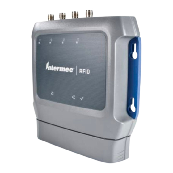
Chapter 1 — About the RFID Reader About the IF2 The IF2 Network Reader is an RFID reader that provides connectivity between tag data and an enterprise system. IF2 Network Reader Note: The IF2 does not ship with RFID antennas. For more information on these accessories, contact your sales representative. -
Page 15: About The Leds
Chapter 1 — About the RFID Reader The reader forwards RFID tag data to the Ethernet network as shown in the next illustration. RFID antenna Container with RFID tag IF2 in a Wired Ethernet Network About the LEDs The IF2 has six LEDs that indicate the status of the reader during operation. - Page 16 Chapter 1 — About the RFID Reader IF2 LED Descriptions (continued) Icon Name Description • Power Over Green if Power Over Ethernet (POE) is Ethernet enabled. • Red if a fault condition is detected. For example, if the power converter for POE does not provide enough power to the IF2, the POE LED stays red indicating a fault condition.
-
Page 17: About The Ready-To-Work Indicator
Chapter 1 — About the RFID Reader About the Ready-to-Work Indicator The blue Ready-to-Work indicator shows when an application is communicating with the Basic Reader Interface (BRI) server or LLRP client on the IF2. The next table explains the different states of the Ready-to-Work indicator. - Page 18 Chapter 1 — About the RFID Reader IF2 Port Descriptions Port Description GPIO General purpose input/output (GPIO) port that connects the IF2 to industrial controls such as relays or indicators. For more information on the IF2 GPIO interfaces, see “About the GPIO Interfaces” on page 80. DC power Connects the reader to a 12 volt DC power source.
-
Page 19: About The Top Panel Ports
Chapter 1 — About the RFID Reader About the Top Panel Ports The IF2 top panel ports consist of four antenna ports, a reset switch, and a USB service port. USB service port Reset switch Antenna port (4 places) IF2 Top Panel Ports The IF2 RFID antenna ports uses Reverse TNC connectors. -
Page 20: How To Communicate With The If2
Chapter 1 — About the RFID Reader How to Communicate with the IF2 By default, the IF2 is configured to be a DHCP client and accepts offers from any DHCP server. Therefore, the IF2 will work out of the box if you connect it to your network and use a DHCP server to assign it an IP address. - Page 21 Chapter 1 — About the RFID Reader 2 Type config and press Enter, and then type config again in the Password field and press Enter. The IF2 Initial Configuration screen appears. 3 If DHCP is enabled, press D. DHCP is disabled and the Ethernet Configuration Options screen appears.
- Page 22 Chapter 1 — About the RFID Reader 6 To set the subnet mask, press 2 and enter the subnet mask value in the entry field. Press Enter to save the changes. To set the IP router address, press 3 and enter the IP router address in the entry field.
-
Page 23: Use The Web Browser Interface
Chapter 1 — About the RFID Reader Use the Web Browser Interface After the IF2 is assigned an IP address, configure the IF2 using the web browser interface. To use the web browser interface, the IF2 must be connected to your wired network. - Page 24 Chapter 1 — About the RFID Reader Note: If a security alert message appears: • Click Yes to continue to the secure login screen. • Click No to cancel. • Click View certificate to see the security certificate before continuing. IF2 Secure Login Screen 4 If necessary, enter a user name and password.
-
Page 25: Save Configuration Changes
Chapter 1 — About the RFID Reader 5 Click Login (or Secure Login in the secure login screen). The Ethernet screen appears and your web browser session is established. For help with configuring network settings, see “Configure the Settings for Your Network” on page 20. For help with configuring RFID reader settings, see “Configure BRI Settings”... -
Page 26: Disable Help In The Web Browser Interface
Chapter 1 — About the RFID Reader Disable Help in the Web Browser Interface By default, the web browser interface shows help text as you move the cursor over items in each screen. Follow the next procedure to disable the help text feature. 1 In the web browser interface, click Help in the upper right corner of the screen. -
Page 27: How To Install The If2
Chapter 1 — About the RFID Reader How to Install the IF2 This section explains how to properly install the IF2 reader and how to mount it to a wall using the IF2 Network Reader Drilling Template Instructions that ships in the box with the IF2. The IF2 should be professionally installed. -
Page 28: Install The If2
Chapter 1 — About the RFID Reader Note: Make sure you provide adequate heat sinking in high temperature environments if you intend to leave the IF2 reading tags continuously. If you externally trigger the IF2 to read a tag for two seconds every 30 seconds, it will not require additional heat sinking. -
Page 29: Connect The If2 To Your Network
Chapter 1 — About the RFID Reader Connect the IF2 to Your Network After you place the IF2 in its mounting location, you can connect it to your network. 1 Install the IF2 in its mounting location. For help, see “How to Install the IF2”... -
Page 30: Set The Date And Time
Chapter 1 — About the RFID Reader Set the Date and Time After you have installed the IF2, you can set the date and time via the web browser interface. 1 Connect to the IF2 via the web browser interface. For help, see “Use the Web Browser Interface”... -
Page 31: Configure Network Settings
Configure Network Settings This chapter describes how to configure network settings for the IF2 and includes these topics: • Configure the Settings for Your Network • Configure Security • Manage Certificates This chapter assumes that you are familiar with your network, networking terms, and the type of security implemented by your network. -
Page 32: Configure The Settings For Your Network
Chapter 2 — Configure Network Settings Configure the Settings for Your Network You use the web browser interface to configure network settings. For more information on using the web browser, see “Use the Web Browser Interface” on page 11. This chapter explains how to use the web browser interface to configure settings for: •... - Page 33 Chapter 2 — Configure Network Settings If DHCP is enabled, you see this screen: If DHCP is disabled, the current values for IP address, subnet mask, and router appear in entry fields: 2 Configure the Ethernet settings. For help, see the next table. Note: Different settings appear in this screen depending on the current DHCP mode for the IF2.
- Page 34 Chapter 2 — Configure Network Settings 3 Click Activate Changes to save your changes and immediately make them active. Ethernet Settings Descriptions Parameter Description Enable DHCP Check this check box if you want the IF2 to get its IP address from a DHCP server.
-
Page 35: Configure Common Network Settings
Chapter 2 — Configure Network Settings Configure Common Network Settings Common network settings are configuration items that apply to the IF2 network interface. This section explains how to use the web browser interface to configure these common network settings: • Hostname •... -
Page 36: Configure Security
Chapter 2 — Configure Network Settings Common Network Settings Descriptions Parameter Description Hostname Name for this IF2. The default is “IF2<serial number of the IF2>”. The hostname can be either a simple hostname, or a qualified domain name (FQDN). If this IF2 obtains its IP address via DHCP, this parameter is sent to the DHCP server. -
Page 37: Control Access Services
Chapter 2 — Configure Network Settings • disable serial port access to the IF2. For help, see “Disable Access Through the Serial Port” on page 30. For general information on securely using the IF2, see “How to Use the IF2 Securely” on page 18. Control Access Services Access services are the different ways that users can access and configure the IF2. -
Page 38: Set Up Logins
Chapter 2 — Configure Network Settings Access Services Descriptions Service Description Enable Web Server Enables access to the IF2 via the web browser interface. Select Enable Web Server (Insecure) to allow users to log in using either a nonsecure (HTTP via port 80) or secure (HTTPS via port 443) web interface. -
Page 39: Configure The If2 To Use A Password Server
Chapter 2 — Configure Network Settings • If you do not want to use a password server, you should change the default login user name and password, and create a read-only password. For help, see “Change the Default Login” on page 29. Configure the IF2 to Use a Password Server If you use a password server to manage users who log in to this IF2, you need to tell the IF2 how to communicate with the password server... - Page 40 Chapter 2 — Configure Network Settings 2 Check the Enable RADIUS check box. A list of RADIUS configuration items appears. 3 Configure the settings. For help, see the next table. 4 Click Activate Changes. 5 Configure the password server database. For help, see the documentation that came with your server.
-
Page 41: Change The Default Login
Chapter 2 — Configure Network Settings Note: USB is not supported on the IF2 with Expanded Memory Option. Change the Default Login If you are not using a password server to authorize user logins, Intermec recommends that you change the default user name and password and create a read-only password. -
Page 42: Disable Access Through The Serial Port
Chapter 2 — Configure Network Settings Password Parameter Descriptions (continued) Parameter Description Read-only Enter the password you need to use to log in to this IF2. This Password password gives the user read-only access to the IF2. This user can view the configuration and execute diagnostics but cannot perform any tasks that affect IF2 operation, such as changing configuration options or upgrading firmware. -
Page 43: Manage Certificates
Chapter 2 — Configure Network Settings 2 Clear the Enable Serial Configuration check box. 3 Click Activate Changes to save your changes and immediately make them active. Manage Certificates The default server certificate on the IF2 (ValidForHTTPSOnly) provides support for secure network applications such as the secure web browser interface, secure LLRP client connections, and secure web services. -
Page 44: Install And Uninstall Certificates
Chapter 2 — Configure Network Settings Install and Uninstall Certificates Once you have determined that you need to install or uninstall a certificate, use this procedure. Note: If you follow the procedure to uninstall all certificates, you will lose the unique server certificate and the trusted CA certificate. You will need to contact your local representative to purchase new certificates. - Page 45 Chapter 2 — Configure Network Settings 4 (Server Certificate only) In the Enter the associated passphrase for this certificate field, carefully enter the passphrase for the certificate. 5 Click Import Certificate. If a Security Alert dialog box appears, click Yes to proceed. IF2 Network Reader User Manual...
- Page 46 Chapter 2 — Configure Network Settings IF2 Network Reader User Manual...
-
Page 47: Develop And Use Rfid Applications
Develop and Use RFID Applications This chapter explains how you can develop and test RFID applications for the IF2 and IF2 with expanded memory option and includes these topics: • About the IF2 Configurations • RFID Applications and the IF2 •... -
Page 48: About The If2 Configurations
Chapter 3 — Develop and Use RFID Applications About the IF2 Configurations The IF2 comes in a standard configuration with no internal memory, or an expanded memory option. • For the IF2, the applications you develop resides on a remote server which communicates with the reader, and all information is processed through the server. -
Page 49: Use The Rfid Resource Kit
Chapter 3 — Develop and Use RFID Applications Use the RFID Resource Kit The Intermec Developer Library RFID Resource Kit includes Java and C# tools you can use to develop applications that enable control of the reader and data management. The resource kit is available as part of the Intermec Developer Library (IDL). -
Page 50: Configure Bri Settings
Chapter 3 — Develop and Use RFID Applications Configure BRI Settings This section explains how to configure BRI settings that control reader operation and communication with your application. • To configure BRI attribute settings that control reader operation, such as read and write tries, tag types, or antenna settings, see the next section, “Changing BRI Attribute Settings.”... -
Page 51: About Bri Attribute Settings
Chapter 3 — Develop and Use RFID Applications About BRI Attribute Settings This section explains the BRI attribute settings that control how the reader operates. For more information, see the Basic Reader Interface Programmer Reference Manual. Tag Types Check the appropriate check boxes to enable RFID operations for these kinds of tags: •... -
Page 52: Field Separator
Chapter 3 — Develop and Use RFID Applications Field Separator Sets the character to be used for separating fields in tag data. Choose from space ( ), comma (,), colon (:), semicolon (;), tab, caret (^), or tilde (~). Default is space. This setting is equivalent to the FIELDSEP BRI attribute. -
Page 53: Select Tries
Chapter 3 — Develop and Use RFID Applications 2 Specify the value (in ms) for the antenna or ID timeout in the entry fields and then click Activate Changes. For more information on ID Timeout and Antenna Timeout, see those topics later in this section. Select Tries (Not supported by EPCglobal Class 1 Gen 2 tags) Sets the number of times a group select is attempted. -
Page 54: Schedule Option
Chapter 3 — Develop and Use RFID Applications Schedule Option Determines how antennas are switched during the inventory process. This attribute controls the behavior of the inventory scheduling parameters. This setting is equivalent to the SCHEDULOPT BRI attribute. ID Tries Sets the maximum number of times the reader executes the identify algorithm before a response is returned to a Read or Write command. -
Page 55: Antenna Field Strength 1 To 4
Chapter 3 — Develop and Use RFID Applications Antenna Field Strength 1 to 4 Sets the RF power level (in dBm) for each of the 4 antenna ports. Valid range is 15 to 30. Default is 30. Note that the maximum power level is dependent on the region that the IF2 is operating in. -
Page 56: View The Bri Server Log
Chapter 3 — Develop and Use RFID Applications 3 Click Activate Changes to save your changes and immediately make them active. BRI Server Parameter Descriptions Parameter Description Enable External Enables/disables external TCP connections to the BRI BRI Connections server. If this check box is not checked, BRI applications will not be able to connect to the IF2. - Page 57 Chapter 3 — Develop and Use RFID Applications 1 Enable BRI logging as described in the previous section, “Configure the BRI Server” on page 2 In the left navigation list, click RFID Services > BRI > BRI Log. The BRI Log screen appears with a list of BRI events. For more information on server events, see the “BRI Event Descriptions”...
-
Page 58: Configure Llrp Settings
Chapter 3 — Develop and Use RFID Applications Configure LLRP Settings The IF2 supports version 1.0.1 of the EPCglobal Low-Level Reader Protocol (LLRP), which establishes a specific interface method between a reader and its corresponding client. Follow the next procedure to configure LLRP settings. For information on LLRP, including standards, see http://www.epcglobalinc.org/standards/llrp. - Page 59 Chapter 3 — Develop and Use RFID Applications 1 From the menu, click RFID Services > LLRP. The LLRP screen appears. 2 Configure LLRP settings as needed. For help, see the “LLRP Settings Descriptions” table. • To disconnect an existing LLRP connection, click Terminate. •...
- Page 60 Chapter 3 — Develop and Use RFID Applications IF2 Network Reader User Manual...
-
Page 61: Install Applications On The If2 With Expanded Memory Option
Install Applications on the IF2 with Expanded Memory Option This chapter explains how you can develop and install applications on the IF2 with Expanded Memory option. • Create a Configuration File • Auto-Start Applications at Boot Time • About .NET Support •... -
Page 62: Create A Configuration File
Chapter 4 — Install Applications on the IF2 with Expanded Memory Option Create a Configuration File When you package your application for installation on the IF2, you need to include a configuration file in the root directory of the archive. The file must be named “userapp.conf” and must include this syntax: AUTOSTART=true|false RUNAFTERINSTALL=true|false... -
Page 63: Auto-Start Applications At Boot Time
Chapter 4 — Install Applications on the IF2 with Expanded Memory Option Note: The IF2 executes applications from their installation directories, so the userapp.conf file does not need to include path information. Auto-Start Applications at Boot Time There are two ways to configure your application to auto-start when the IF2 boots: •... -
Page 64: Execute Java Applications
Chapter 4 — Install Applications on the IF2 with Expanded Memory Option For more sophisticated Java development, the IF2 supports the open standard OSGi service-oriented architecture. This allows system administrators to install, uninstall, enable, and disable system services (also known as bundles) without having to reboot the IF2 each time. To use OSGi effectively, you need an OSGi server. -
Page 65: Java Support For Microsoft Sql Server And Sybase
Chapter 4 — Install Applications on the IF2 with Expanded Memory Option Java Support for Microsoft SQL Server and Sybase The IF2 jTDS driver (version 1.2) provides JDBC capabilities to Java applications running on the IF2. You need to include the location of JDBC drivers in the class path. -
Page 66: Manage Applications
Chapter 4 — Install Applications on the IF2 with Expanded Memory Option Manage Applications To maximize IF2 resources, you can start, stop, or uninstall IF2 edgeware applications or your installed applications from the web browser interface. You can also configure applications to auto-start at boot time. -
Page 67: About The Edgeware Applications
Chapter 4 — Install Applications on the IF2 with Expanded Memory Option About the Edgeware Applications Edgeware applications are supplied by Intermec and its partner developers, and provide immediate functionality for your RFID system. The IF2 includes these edgeware applications: •... -
Page 68: About The Developer Tools
Chapter 4 — Install Applications on the IF2 with Expanded Memory Option About the Developer Tools Use the Developer Tools for basic testing of your RFID system. The Developer Tools support these features: • General purpose input/output (GPIO) testing. For help, see the next section, “Test the GPIO Interfaces.”... -
Page 69: Send Bri Commands And Running Scripts
Chapter 4 — Install Applications on the IF2 with Expanded Memory Option Send BRI Commands and Running Scripts You can send BRI commands to the IF2 through the web browser interface. 1 From the menu, click Edgeware Applications > Developer Tools >... - Page 70 Chapter 4 — Install Applications on the IF2 with Expanded Memory Option 3 To save your JavaScript code to the IF2 work buffer, click Save As and enter a new file name in the entry field. Click OK. If you previously saved your JavaScript, click on the drop-down menu and select the file name to reload it in the JavaScript Code box.
-
Page 71: Manage, Troubleshoot, And Upgrade The If2
Manage, Troubleshoot, and Upgrade the This chapter includes information on managing the IF2 and includes these topics: • Manage the IF2 • Use the Device Configuration Web Service • Open a Serial or USB Connection to the IF2 • Maintain the IF2 •... -
Page 72: Manage The If2
Chapter 5 — Manage, Troubleshoot, and Upgrade the IF2 Manage the IF2 There are two methods you can use to manage the IF2. You can use: • a web browser. For help, see “Use the Web Browser Interface” on page 11. This manual assumes you are using this method for all procedures. -
Page 73: Open A Serial Or Usb Connection To The If2
Chapter 5 — Manage, Troubleshoot, and Upgrade the IF2 2 To disable web services over a secure connection, clear the Enable Device Web Services (Secure) check box, and then click Activate Changes. To disable web services over an insecure connection, uncheck the Enable Device Web Services (Insecure) check box, and then click Activate Changes. -
Page 74: Open A Serial Connection To The If2
Chapter 5 — Manage, Troubleshoot, and Upgrade the IF2 Open a Serial Connection to the IF2 If you are opening a serial connection to the IF2, you need: • a null-modem cable (P/N 059167). • a communications program such as HyperTerminal. Note: If you have Microsoft ActiveSync running on your desktop PC, disable ActiveSync to make the serial port available. -
Page 75: Open A Usb Connection To The If2
Chapter 5 — Manage, Troubleshoot, and Upgrade the IF2 • You can restore default settings. For help, see “Restore Default Settings with a Serial Connection” on page 69. • You can open a BRI session. Open a USB Connection to the IF2 If you are connecting the IF2 using a USB connection, you need: •... - Page 76 Chapter 5 — Manage, Troubleshoot, and Upgrade the IF2 [GSerialAddReg] HKR,,DevLoader,,*ntkern HKR,,NTMPDriver,,usbser.sys HKR,,EnumPropPages32,,"MsPorts.dll,SerialPortPropPageProvider" [GSerialInstall.Services] AddService = usbser,0x0002,GSerialService [GSerialService] DisplayName = %GSERIAL_DISPLAY_NAME% ServiceType = 1 ; SERVICE_KERNEL_DRIVER StartType = 3 ; SERVICE_DEMAND_START ErrorControl = 1 ; SERVICE_ERROR_NORMAL ServiceBinary = %10%\System32\Drivers\usbser.sys LoadOrderGroup = Base [Strings] LINUX = "Linux"...
-
Page 77: Maintain The If2
Chapter 5 — Manage, Troubleshoot, and Upgrade the IF2 • You can assign an initial IP address to the IF2 for configuration. For help, see “Assign an Initial IP Address” on page 8. • You can restore default settings. For help, see “Restore Default Settings with a Serial Connection”... -
Page 78: View The About Screen
Chapter 5 — Manage, Troubleshoot, and Upgrade the IF2 View the About Screen The About screen lists installed software versions, serial numbers, and other IF2-specific information. • From the menu, click About. The About screen appears. This screen is read-only. The About screen includes this information: •... -
Page 79: Restore The If2 To The Default Configuration
Chapter 5 — Manage, Troubleshoot, and Upgrade the IF2 Restore the IF2 to the Default Configuration Note: Restoring default settings as described in this section does not affect security certificates you have installed. There are four ways to restore the default configuration on the IF2: •... -
Page 80: Restore Default Settings With The Web Browser
Chapter 5 — Manage, Troubleshoot, and Upgrade the IF2 Restore Default Settings with the Web Browser If you are having problems with the IF2, you can use the web browser interface to restore the default settings to the IF2. 4 From the menu, click Maintenance > Configuration. The Configuration screen appears and displays all configuration changes from the factory default settings. -
Page 81: Restore Default Settings With The Reset Switch
Chapter 5 — Manage, Troubleshoot, and Upgrade the IF2 Restore Default Settings with the Reset Switch If you are having problems with the IF2, you can press the reset switch to restore the default settings to the IF2. 1 Make sure the IF2 is powered on. 2 Using a paper clip, push and hold the reset switch for three seconds. -
Page 82: Reboot The If2
Chapter 5 — Manage, Troubleshoot, and Upgrade the IF2 Reboot the IF2 You can reboot the IF2 from the web browser interface as described in the next procedure. For example, you may need to reboot the IF2 to enable changes in an application. 1 From the menu, click Maintenance >... -
Page 83: Troubleshoot The If2
Chapter 5 — Manage, Troubleshoot, and Upgrade the IF2 Troubleshoot the IF2 This section includes lists of problems and possible solutions. Problems While Working with RFID Many problems you may encounter when working with your RFID system can be solved by carefully checking the RFID settings and changing them accordingly. -
Page 84: Connect Directly To The Rfid Module
Chapter 5 — Manage, Troubleshoot, and Upgrade the IF2 Connect Directly to the RFID Module If your application does not appear to be communicating with the IF2 RFID module, you can use a communications program to verify that the RFID module is working properly. You need to know the IF2 IP address to connect directly to the RFID module. - Page 85 Chapter 5 — Manage, Troubleshoot, and Upgrade the IF2 5 Type ATTRIB and press Enter. A list of the current settings for the RFID module appears, indicating that the module is receiving commands. If the list does not appear, there may be a problem with the RFID module.
-
Page 86: Problems With Connectivity
Chapter 5 — Manage, Troubleshoot, and Upgrade the IF2 Problems With Connectivity When troubleshooting problems with connectivity, make sure you know and understand these network-specific items: • TCP/IP settings • COM port settings for serial connections You should also make sure all physical network connectors and cables are in good working order. -
Page 87: Call Customer Support
Chapter 5 — Manage, Troubleshoot, and Upgrade the IF2 Call Customer Support You may need to call support if you have problems operating the IF2. Before calling, be sure you can answer the following questions: • What kind of network are you using? What were you doing when the error occurred? •... -
Page 88: Upgrade Firmware
Intermec. Be sure to contact your Intermec RFID system consultant before upgrading. To locate IF2 upgrades, see the previous section, “Access Web Pages.” 1 Download the Intermec IF2 OS Upgrade Package utility from the Intermec web site. For help, see the previous section, “Access Web Pages.”... -
Page 89: Configure The Firmware Upgrade
Chapter 5 — Manage, Troubleshoot, and Upgrade the IF2 Configure the Firmware Upgrade The Upgrade Package installer configures IF2 firmware upgrades. The configuration you need depends on the method you use to upgrade the IF2: • Using the web browser interface. •... -
Page 90: Install The Firmware Upgrade
Chapter 5 — Manage, Troubleshoot, and Upgrade the IF2 Install the Firmware Upgrade You can use the web browser interface to upgrade the firmware on the IF2. Do not cycle power to the IF2 during the upgrade. If power is lost during the upgrade, the IF2 may require factory repair. -
Page 91: Use The If2 Gpio Interfaces
Use the IF2 GPIO Interfaces This chapter explains how to access the IF2 general purpose input/output (GPIO) interfaces and how to connect industrial controls such as motion sensors or indicator lamps to the IF2. This chapter includes the following topics: •... -
Page 92: About The Gpio Interfaces
Chapter 6 — Use the IF2 GPIO Interfaces About the GPIO Interfaces The IF2 has four general purpose input and output (GPIO) interfaces. You connect external controls such as motion sensors or indicator lamps to the GPIO interfaces, which can then trigger IF2 operations. Each interface is electrically isolated from the IF2 and designed for low voltage DC loads. -
Page 93: Use The Input Interfaces
Chapter 6 — Use the IF2 GPIO Interfaces • The Sensor Kit (P/N 203-859-xxx). This motion sensor connects directly to the IF2 GPIO port and triggers the input interfaces. The kit includes a mounting bracket and connecting cable. • The Light Stack and Sensor Kit (P/N 203-860-xxx). This kit includes the light stack, a sensor with mounting bracket, and connecting cable. -
Page 94: If2 Powered Input
Chapter 6 — Use the IF2 GPIO Interfaces IF2 Powered Input This is the simplest way to connect a control to an IF2 input interface. If the external control device is a switch, you can connect one side of the switch to an IF2 +Input pin, and the other side of the switch to one of the +12 VDC sources. -
Page 95: Open Collector Input Interface
Chapter 6 — Use the IF2 GPIO Interfaces Open Collector Input Interface The input can be connected to an open collector interface of an external device. This typically implies that the grounds are tied together for the two systems. The common ground can be a source of input noise, so you should follow good grounding practices for both the IF2 and the input device. -
Page 96: Switch The High Side With If2 Power
Chapter 6 — Use the IF2 GPIO Interfaces Since the outputs are optically isolated, you can configure each one to switch the high side or the low side of the load. You can power the load directly from the IF2 or from an external power supply. In a typical application, the outputs control indicator lamps that signal good reads or errors. -
Page 97: Switch The Low Side With If2 Power
Chapter 6 — Use the IF2 GPIO Interfaces Switch the Low Side with IF2 Power For low side switching applications, the lamp power is routed to all the lamps in common and the low side of the load is routed to the switch. -
Page 98: Switching The High Side With External Power
Chapter 6 — Use the IF2 GPIO Interfaces Switching the High Side With External Power To use external power (5 to 48 VDC) to switch the high side, connect the Ground pin to the ground system of the external power supply, and connect the positive side of the external supply to the +Output pin. -
Page 99: Drive A Dc Relay To Control An Ac Load
Chapter 6 — Use the IF2 GPIO Interfaces Drive a DC Relay to Control an AC Load While the IF2 outputs are designed to switch DC loads, they can drive relays that control AC loads. The next illustration shows how to connect such a system to an IF2 output. -
Page 100: Use The Power Interface
Chapter 6 — Use the IF2 GPIO Interfaces Use the Power Interface The IF2 GPIO interface provides 12 VDC at 0.5 A for powering external inputs and loads, eliminating the need for an external DC supply and simplifying the system installation. The GPIO interface power has an internal thermal fuse that trips if the load exceeds 0.5 A. -
Page 101: Specifications
Specifications This appendix includes physical and electrical specifications for the IF2 and information about the port pin assignments. -
Page 102: If2 Specifications
Appendix A — Specifications IF2 Specifications Specifications Values Height 19.9 cm (7.87 in) Length 18.8 cm (7.42 in) Width 4.3 cm (1.7 in) Weight 1 kg (2.2 lb) DC electrical rating 12 V +/- 5%, 30 W (55 V, 30 W for High Power Over Ethernet) Operating temperature -20 ºC to +55 ºC (-4ºF to +131 ºF) Storage temperature... -
Page 103: Rfid Specifications
Appendix A — Specifications RFID Specifications Specifications Values Protocols Supported EPCglobal Class 1 Gen 2 ISO 18000-6B Generation 1 ISO 18000-6B Generation 2 Frequency Range 865.6 - 867.6 MHz, or 902 - 928 MHz Output power Minimum: 1 dBm Maximum: 30.0 dBm 865-867 MHz, 900 MHz Occupied frequency <250 KHz... - Page 104 Appendix A — Specifications GPIO Port Pin Assignments (continued) Description Active Polarity -Input 3 Low-RTN -Input 4 Low-RTN Ground Ground +Output 1 High (10-48 V) Ground +Output 2 High (10-48 V) Ground +Output 3 High (10-48 V) Ground +Output 4 High (10-48 V) +Input 1 High (10-48 V)
-
Page 105: Serial Ports (Com1)
Appendix A — Specifications Serial Ports (COM1) Pin 1 Pin 9 Serial Port Pin Assignments Description Active Polarity Receive data (RXD) Transmit data (TXD) Signal ground Request to send (RTS) Clear to send (CTS) IF2 Network Reader User Manual... -
Page 106: Ethernet Port
Appendix A — Specifications Ethernet Port Pin 1 Ethernet Port Pin Assignments Description Ethernet TX+/Spare POE return Ethernet TX-/Spare POE return Ethernet RX+/Spare POE 48 VDC Not used/POE 48 VDC Not used/POE 48 VDC Ethernet RX-/Spare POE 48 VDC Not used/POE return Not used/POE return IF2 Network Reader User Manual... - Page 108 Honeywell 16201 25th Avenue West Lynnwood, Washington 98087 U.S.A. www.honeywellaidc.com IF2 Network Reader User Manual *935-040-003* P/N 935-040-003...
Need help?
Do you have a question about the Intermec IF2 and is the answer not in the manual?
Questions and answers