ZyXEL Communications ES-1528 User Manual
Zyxel es-1528 ethernet switch user's guide
Hide thumbs
Also See for ES-1528:
- Support notes (9 pages) ,
- Specifications (4 pages) ,
- Sales manual (8 pages)
Table of Contents
Advertisement
Advertisement
Table of Contents
Troubleshooting

Related Manuals for ZyXEL Communications ES-1528


Summary of Contents for ZyXEL Communications ES-1528
- Page 1 ES-1528 Ethernet Switch User’s Guide Version 1.12 10/2006 Edition 1 www.zyxel.com...
-
Page 3: About This User's Guide
About This User's Guide Intended Audience This manual is intended for people who want to configure the switch using the web configurator. You should have at least a basic knowledge of TCP/IP networking concepts and topology. Related Documentation • Quick Start Guide The Quick Start Guide is designed to help you get up and running right away. -
Page 4: Warnings And Notes
Syntax Conventions • The ES-1528 may be referred to as the “switch”, the “device” or the “system” in this User’s Guide. • Product labels, screen names, field labels and field choices are all in bold font. - Page 5 Icons Used in Figures Figures in this User’s Guide may use the following generic icons. The switch icon is not an exact representation of your device. ES-1528 Server Telephone ES-1528 User’s Guide Computer Notebook computer DSLAM Firewall Switch Router Document Conventions...
-
Page 6: Safety Warnings
• Do not use the device outside, and make sure all the connections are indoors. There is a remote risk of electric shock from lightning. • Do NOT obstruct the device ventilation slots, as insufficient airflow may harm your device. Safety Warnings ES-1528 User’s Guide... - Page 7 Safety Warnings This product is recyclable. Dispose of it properly. ES-1528 User’s Guide...
- Page 8 Safety Warnings ES-1528 User’s Guide...
-
Page 9: Table Of Contents
Auto Denial of Service (DoS) ... 89 Auto VoIP ... 93 Management and Troubleshooting ... 95 Event Logging ... 97 SNMP ... 105 RMON-Lite ...119 Dynamic ARP ... 133 Troubleshooting ... 137 Appendices and Index ... 145 ES-1528 User’s Guide Contents Overview Contents Overview... - Page 10 Contents Overview ES-1528 User’s Guide...
-
Page 11: Table Of Contents
2.1 Freestanding Installation ... 31 2.2 Mounting the Switch on a Rack ... 32 2.2.1 Rack-mounted Installation Requirements ... 32 2.2.2 Attaching the Mounting Brackets to the Switch ... 32 2.2.3 Mounting the Switch on a Rack ... 33 Chapter 3 Hardware Overview... - Page 12 6.1 Port Status ... 55 6.2 Port Configuration ... 56 Chapter 7 System and Port Statistics... 59 7.1 Overview ... 59 7.2 Statistics Summary 7.3 Port Statistics ... 60 ... 44 ... 47 ... 47 ... 52 ... 59 ES-1528 User’s Guide...
- Page 13 Port Rate Limit and Storm Control... 79 12.1 Port Rate Screen ... 79 12.1.1 Rate Limit Screen ... 80 12.1.2 Broadcast Storm Control Setup ... 81 Chapter 13 Level 2 (L2) Management ... 83 ES-1528 User’s Guide ... 63 ... 73 Table of Contents...
- Page 14 18.1.3 SNMP EngineID 18.2 SNMP Group ... 107 18.2.1 SNMP Group - Create ... 108 18.2.2 SNMP Group - Modify ... 109 18.3 SNMP User ... 109 ... 83 ... 84 ... 84 ... 106 ... 107 ES-1528 User’s Guide...
- Page 15 Chapter 21 Troubleshooting... 137 21.1 Problems Starting Up the Switch ... 137 21.2 Problems Accessing the Switch ... 137 21.2.1 Pop-up Windows, JavaScripts and Java Permissions ... 137 ES-1528 User’s Guide ... 133 ... 134 ... 135 Table of Contents...
- Page 16 Table of Contents Part IV: Appendices and Index ... 145 Appendix A Product Specifications... 147 Appendix B IP Addresses and Subnetting ... 151 Appendix C Legal Information ... 159 Appendix D Customer Support... 163 Index... 167 ES-1528 User’s Guide...
-
Page 17: List Of Figures
Figure 4 Shared Server Using VLAN Example ... 29 Figure 5 Attaching Rubber Feet ... 31 Figure 6 Attaching the Mounting Brackets ... 32 Figure 7 Mounting the Switch on a Rack ... 33 Figure 8 Front Panel ... 35 Figure 9 Transceiver Installation Example ... 36 Figure 10 Installed Transceiver ... - Page 18 Figure 77 RMON History Statistics: Control ... 125 Figure 78 RMON Alarm: Overview..126 Figure 79 RMON Alarm : Create New Alarm ... 127 Figure 80 RMON Event : Overview..128 Figure 81 RMON Event Configuration Screens ... 129 ES-1528 User’s Guide...
- Page 19 Figure 93 Security Settings - Java ... 142 Figure 94 Java (Sun) ... 143 Figure 95 Network Number and Host ID ... 152 Figure 96 Subnetting Example: Before Subnetting ... 154 Figure 97 Subnetting Example: After Subnetting ... 155 ES-1528 User’s Guide...
- Page 20 List of Figures ES-1528 User’s Guide...
-
Page 21: List Of Tables
Table 33 Logging ... 98 Table 34 Logging - Add Server ... 99 Table 35 Logging - RAM/Flash ... 100 Table 36 Searching - RAM/Flash Logs ... 102 Table 37 Logs: Search Results ... 102 Table 38 SNMP Commands ... 106 ES-1528 User’s Guide... - Page 22 Table 65 ARP Table ... 134 Table 66 ARP Table ... 135 Table 67 ARP Table ... 136 Table 68 Troubleshooting the Start-Up of Your Switch ... 137 Table 69 Troubleshooting Accessing the Switch ... 137 Table 70 Firmware Features ... 147 Table 71 General Product Specifications ...
- Page 23 List of Tables Table 82 Eight Subnets ... 156 Table 83 24-bit Network Number Subnet Planning ... 157 Table 84 16-bit Network Number Subnet Planning ... 157 ES-1528 User’s Guide...
- Page 24 List of Tables ES-1528 User’s Guide...
-
Page 25: Introduction And Hardware Overview
Introduction and Hardware Overview Getting to Know Your Switch (27) Hardware Installation and Connection (31) Hardware Overview (35) -
Page 27: Getting To Know Your Switch
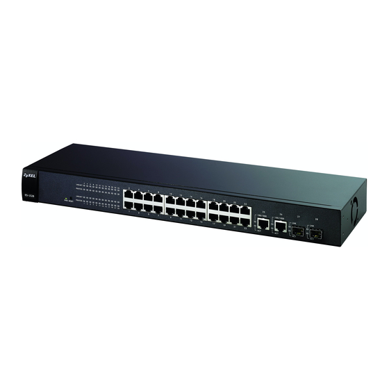
This chapter introduces the main features and applications of the switch. 1.1 Introduction The ES-1528 is an Ethernet switch with 24 10/100Mbps ports, two RJ-45 Gigabit ports for stacking and 2 mini-GBIC slots for fiber connections. With its built-in web configurator, managing and configuring the switch is easy. -
Page 28: Bridging Example
Sales) to the corporate backbone. It can alleviate bandwidth contention and eliminate server and network bottlenecks. All users that need high bandwidth can connect to high-speed department servers via the switch. You can provide a super-fast uplink connection by using a Gigabit Ethernet/mini-GBIC port on the switch. -
Page 29: Ieee 802.1Q Vlan Application Examples
VLAN 1. Ports can belong to other VLAN groups too. Figure 4 Shared Server Using VLAN Example ES-1528 User’s Guide Chapter 1 Getting to Know Your Switch Chapter 8 on page... - Page 30 Chapter 1 Getting to Know Your Switch ES-1528 User’s Guide...
-
Page 31: Hardware Installation And Connection
4 Remove the adhesive backing from the rubber feet. 5 Attach the rubber feet to each corner on the bottom of the switch. These rubber feet help protect the switch from shock or vibration and ensure space between devices when stacking. -
Page 32: Mounting The Switch On A Rack
2.2.2 Attaching the Mounting Brackets to the Switch 1 Position a mounting bracket on one side of the switch, lining up the four screw holes on the bracket with the screw holes on the side of the switch. -
Page 33: Mounting The Switch On A Rack
2.2.3 Mounting the Switch on a Rack 1 Position a mounting bracket (that is already attached to the switch) on one side of the rack, lining up the two screw holes on the bracket with the screw holes on the side of the rack. - Page 34 Chapter 2 Hardware Installation and Connection ES-1528 User’s Guide...
-
Page 35: Hardware Overview
H A P T E R This chapter describes the front panel and rear panel of the switch and shows you how to make the hardware connections. 3.1 Panel Connections and the RESET Button The figure below shows the front panel of the switch. -
Page 36: Default Ethernet Settings
There are two mini-GBIC (Gigabit Interface Converter) slots for mini-GBIC transceivers. A transceiver is a single unit that houses a transmitter and a receiver. The switch does not come with transceivers. You must use transceivers that comply with the SFP Transceiver MultiSource Agreement (MSA). -
Page 37: The Reset Button
When you use the RESET button all of your configuration settings will be lost. Use the default IP address (192.168.1.1) and user name (admin) and password (admin) to log back into the switch. It may take up to 2 minutes for the switch to restart when you reload the default configuration file. -
Page 38: Rear Panel
Make sure you are using the correct power source as shown on the panel. To connect the power to the switch, insert the female end of power cord to the power receptacle on the rear panel. Connect the other end of the supplied power cord to a 100~240V AC, 1.5A power outlet. - Page 39 Table 2 LEDs (continued) COLOR GBIC Slots Green Green ES-1528 User’s Guide STATUS DESCRIPTION The port has a successful connection. No Ethernet device is connected to this port. Blinking The port is receiving or transmitting data. Chapter 3 Hardware Overview...
- Page 40 Chapter 3 Hardware Overview ES-1528 User’s Guide...
-
Page 41: Basic & Advanced Settings
Basic & Advanced Settings The Web Configurator (43) System (49) Port Settings (55) System and Port Statistics (59) VLAN (63) Trunking (67) Mirroring (69) QoS (71) Port Rate Limit and Storm Control (79) Level 2 (L2) Management (83) Cable Diagnostics (87) Auto Denial of Service (DoS) (89) Auto VoIP (93) -
Page 43: The Web Configurator
4.2 System Login 1 Start your web browser. 2 Type “http://” and the IP address of the switch (for example, the default is 192.168.1.1) in the Location or Address field. Press [ENTER]. 3 The login screen appears. The default username is admin and associated default password is admin. -
Page 44: The Status Screen
4.3 The Status Screen The System screen is the first screen that displays when you access the web configurator. The following figure shows the navigating components of the web configurator screen. Figure 15 Web Configurator Home Screen (System) ES-1528 User’s Guide... -
Page 45: The Led Panel
A - The LED panel displays the port status. B - The navigation panel has links to screens that let you configure the switch features. C - The function frame allows you to view and edit individual feature settings. D - Use the Help link to find out more information about the fields in the screen you are configuring. - Page 46 DESCRIPTION Statistics Use these screen to view system statistics such as the number of packets received on the switch, collisions and errors and to view statistics for individual ports on the switch. VLAN Use these screens to create new IEEE 802.1Q VLANs as well as view the status and edit existing IEEE 802.1Q VLANs on the switch.
-
Page 47: Change Your Password
Use the RESET button on the front panel of the switch to reset the switch back to factory defaults. Press and hold the RESET button for one second. The switch will reload its factory defaults. -
Page 48: Logging Out Of The Web Configurator
Chapter 4 The Web Configurator The switch is now reinitialized with a default configuration file including the default administrator username (admin) and password (admin). The IP address of the switch also reverts to the default 192.168.1.1. 4.7 Logging Out of the Web Configurator Click Logout in the navigation panel to exit the web configurator. -
Page 49: System
DESCRIPTION Device Name This read-only field displays the name of your switch. Firmware This field displays the version number of the switch 's current firmware. Click Version Upgrade to go to the firmware upgrade screen. See Build Date This field displays the date of the currently installed firmware. -
Page 50: Configure Ip Address
Enabled/Disabled to change the L2 Table Aging settings. Backup settings Click this link to create and save a backup configuration file. See page Restore Click this link to upload an existing configuration file to the switch. See settings on page 5.1.1 Configure IP Address Use the Configure IP Address screen to set up the IP address manually. -
Page 51: Backup Settings
Figure 21 Configure L2 Table Aging Select the Enable L2 Table Aging checkbox and enter the amount of time in seconds (up to 1048575) that the switch remembers MAC address entries. Select “0” to disable L2 table aging. Click Apply to save your configuration changes. -
Page 52: System: Change Password
5.2 System: Change Password Use the Change Password screen to change the administrator username and password for the switch. Click System > Password to view the screen as shown. Figure 24 System: Password The following table describes the labels in this screen. -
Page 53: System: Restart/Reset
Figure 25 Firmware Upgrade Type the path and file name of the firmware file you wish to upload to the switch in the File Path text box or click Browse to locate it. After you have specified the file, click Upgrade. - Page 54 Chapter 5 System ES-1528 User’s Guide...
-
Page 55: Port Settings
This chapter describes how to view and configure the port settings on the switch. 6.1 Port Status Use this screen to view switch port settings. Click System > Port in the navigation panel to display the Port Status screen. Figure 27 Port Status The following table describes the labels in this screen. -
Page 56: Port Configuration
Auto Negotiate Select Enable and the port will negotiate the speed, duplex mode and flow control settings with the peer port. If the peer port does not support auto-negotiation or turns off this feature, the switch determines the connection speed by detecting the signal on the cable and using half duplex mode. - Page 57 Table 9 Port Configuration (continued) LABEL DESCRIPTION PVID Enter a number identifying an existing VLAN. The switch tags the incoming untagged frames on that port so that the frames are forwarded to the VLAN group that the tag defines. Apply Click Apply to save your changes to the switch.
- Page 58 Chapter 6 Port Settings ES-1528 User’s Guide...
-
Page 59: System And Port Statistics
The following table describes the labels in this screen. Table 10 Statistics LABEL DESCRIPTION Clear Counters Click this to reset all counters to zero. Refresh Click this to retrieve the current information from the switch and update this screen. ES-1528 User’s Guide... -
Page 60: Port Statistics
UnicastPkts Figure 30 on page 60). DESCRIPTION Click this to retrieve the current information from the switch and update this screen. This field displays the port number you are viewing. This field shows the number of octets transmitted. This field shows the number unicast packets transmitted. - Page 61 BytePkts were between 128 and 255 octets in length. 256-511 This field shows the number of packets (including bad packets) received that BytePkts were between 256 and 511 octets in length. ES-1528 User’s Guide Chapter 7 System and Port Statistics...
- Page 62 This field shows the number of packets (including bad packets) received that were between 512 and 1023 octets in length. This field shows the number of packets (including bad packets) received that were between 1024 and 1522 octets in length. ES-1528 User’s Guide...
-
Page 63: Vlan
A tagged VLAN uses an explicit tag (VLAN ID) in the MAC header to identify the VLAN membership of a frame across bridges - they are not confined to the switch on which they were created. The VLANs can be created statically by hand or dynamically through GVRP. The VLAN ID associates a frame with a specific VLAN and provides the information that switches need to process the frame across the network. -
Page 64: Static Vlan
VLANs. Click VLAN in the navigation • (Orange) When the packet leaves this member port, the VLAN tag is added. • (Turquoise) When the packet leaves this member port, the VLAN tag is removed. ES-1528 User’s Guide... -
Page 65: Create Ieee 802.1Q Vlan Screen
U - This indicates that this port is a member of the VLAN. When the packet leaves the member port, the VLAN tag is removed. Create Click Create to add this VLAN to the switch. Cancel Click Cancel to return to the VLAN status screen without making any changes. -
Page 66: Figure 33 Vlan: Edit Vlan
U - This indicates that this port is a member of the VLAN. When the packet leaves the member port, the VLAN tag is removed. Apply Click Apply to create the VLAN or update the VLAN’s configuration. ES-1528 User’s Guide... -
Page 67: Trunking
The switch uses a traffic distribution algorithm to balance traffic between trunk members. The switch allows you to specify what criteria it should use to calculate the most efficient distribution of traffic. The choices are Source MAC Address (SA), Destination MAC Address (DA) or both (SA + DA). -
Page 68: Figure 34 Trunk Setting
Click this to delete the port from the trunk group you selected in the Trunk id field. Trunk 1 ... This summary table lists all the trunks. Trunk Group Member column indicates which Trunk 6 ports are members of the trunk group. Apply Click Apply to save your changes to the switch. ES-1528 User’s Guide... -
Page 69: Mirroring
The Mirror To (monitor) port is the port you copy the traffic to in order to examine it in more detail without interfering with the traffic flow on the original port(s). Select the monitor port. Apply Click Apply to save your changes to the switch. ES-1528 User’s Guide Mirroring... - Page 70 Chapter 10 Mirroring ES-1528 User’s Guide...
-
Page 71: Qos
Strict priority scheduling services the remaining queues using WRR. As traffic comes into the switch, traffic on the highest priority queue, Queue 3 is transmitted first. Only when that queue empties, traffic on the lower priority queues is transmitted using WRR scheduling. -
Page 72: Qos Enhancement
The switch allows you to choose one of the following methods for assigning priority to incoming packets on the switch: Port Based QoS - Assign priority to packets based on the incoming port on the switch. See Section 11.4.1 on page DSCP Based QoS - Assign priority to packets based on their Differentiated Services Code Points (DSCPs). -
Page 73: Change Number Of Queues
Click Apply to save your changes to the switch. 11.3.1 Change Number of Queues Use the Change Number of Queues screen to edit the number of queues on the switch. Click Change in the QoS Setting screen to view the following screen. -
Page 74: Advanced Qos Settings
Port Based QoS, DSCP Based QoS, ToS Based QoS or IP Address Based QoS. 11.4.1 Port Based QoS You can configure the switch to assign a IEEE 802.1p priority to packets based on the ingress (incoming) port of the packet. Select Port Based QoS in the QoS Enhancement Setting screen to view the following screen. -
Page 75: Dscp Based Qos
IP header. The DS field contains a 2-bit unused field and a 6-bit DSCP field which can define up to 64 service levels. You can configure the DSCP to IEEE 802.1p mapping to allow the switch to prioritize all traffic based on the incoming DSCP value according to the DiffServ to IEEE 802.1p mapping table. -
Page 76: Tos Based Qos
Settings 11.4.5 ToS Based QoS You can configure the switch to assign a IEEE 802.1p priority to packets coming into the switch with Type of Service (ToS) priority assigned to them. Select ToS Based QoS in the QoS Enhancement Setting screen to view the following screen. -
Page 77: Ip Address Based Qos
Settings 11.4.6 IP Address Based QoS You can configure the switch to assign a higher priority to packets coming into the switch from specific IP addresses. Select IP Address Based QoS in the QoS Enhancement Setting screen to view the following screen. -
Page 78: Figure 41 Ip Address Based Qos
MASK, you click the Change button in this screen. Click DELETE in the Delete column to Priority, remove this IP address based QoS entry from the switch. Delete Apply Click this when you have reviewed the changes you want to make and you want to save Change them to the switch’s memory. -
Page 79: Port Rate Limit And Storm Control
The following table describes the related labels in this screen. Table 22 Rate Limit and Storm Control LABEL DESCRIPTION Port This field displays the port number. Click on an individual port number to configure rate limits on that port. ES-1528 User’s Guide Control... -
Page 80: Rate Limit Screen
This value changes depending on the number of Tokens Added Per Interval. Tokens The switch uses a “Token Bucket” algorithm to limit the outgoing rate on the ports and Added Per to limit the largest amount of packets that can leave the port in any one instance. -
Page 81: Broadcast Storm Control Setup
Broadcast storm control limits the number of broadcast, multicast and unknown unicast (also referred to as Destination Lookup Failure or DLF) packets the switch receives per second on the ports. When the maximum number of allowable broadcast, multicast and unknown unicast packets is reached per second, the subsequent packets are discarded. -
Page 82: Table 24 Broadcast Storm Control
Storm Control Select the number of packets (of the type specified in the Storm Control Type Rate field) per second the switch can receive per second. Apply Click Apply to save your changes to the switch. ES-1528 User’s Guide... -
Page 83: Level 2 (L2) Management
This is the index number of the static MAC address entry. Source MAC This field displays the MAC address of a manually entered MAC address entry. This field displays the VID of a manually entered MAC address entry. ES-1528 User’s Guide... -
Page 84: Add A Static Mac Address Entry
Click this to add this entry into the MAC address table. 13.2 Viewing the L2 Address Table Use the L2 Address Table screen to view entries in the MAC address table. Click L2 Address > Display in the navigation panel to display the screen as shown. ES-1528 User’s Guide... -
Page 85: Figure 47 Display L2 Address Table
Type This field displays whether this entry was entered manually into the L2 address table - static or whether it was learned by the switch - dynamic. ES-1528 User’s Guide Chapter 13 Level 2 (L2) Management... - Page 86 Chapter 13 Level 2 (L2) Management ES-1528 User’s Guide...
-
Page 87: Cable Diagnostics
This chapter explains the Cable Diagnostics screen. 14.1 Diagnostics Overview The cable diagnostics function works with systems using CAT-5 twisted-pair cables. The switch can perform basic cable diagnostics. Click Cable Diagnostic in the navigation panel to view the screen as shown. Figure 48 Cable Diagnostic The following table describes the labels in this screen. - Page 88 Chapter 14 Cable Diagnostics ES-1528 User’s Guide...
-
Page 89: Auto Denial Of Service (Dos)
15.1 About Denial of Service Attacks Denial of Service (DoS) attacks try to disable a device or network so users no longer have access to network resources. The switch has features which automatically detect and thwart currently known DoS attacks. -
Page 90: Global Auto Dos Attack Prevention
15.2 Global Auto DoS Attack Prevention Use the Global Auto DoS Attack Prevention screen to configure DoS attack prevention settings for the switch. Click Auto DoS in the navigation panel to open the following screen. Figure 49 Global Auto DoS Attack Prevention The following table describes the labels in this screen. -
Page 91: Figure 50 Advanced Auto Dos Attack Prevention
For Ping and SYN/SYN-ACK Flooding attacks you can specify thresholds for triggering the dropping of packets by the switch. Select: • 64 kbps - the switch will drop packets when the rate of incoming Ping or SYN/ SYN-ACK packets reaches this limit. •... - Page 92 Chapter 15 Auto Denial of Service (DoS) ES-1528 User’s Guide...
-
Page 93: Auto Voip
VoIP phones. 16.2 Auto VoIP Settings Use the Auto VoIP Settings enable automatic assignment of high priority to VoIP packets passing through the switch. Click Auto VoIP in the navigation panel to view the following screen. ES-1528 User’s Guide... -
Page 94: Figure 51 Auto Voip Settings
Select Disable if you don’t want to give higher priority to VoIP traffic or select IP Phone to give the highest priority to SIP, MGCP and SCCP packets passing through the switch. Apply Click Apply to save your changes to the switch. ES-1528 User’s Guide... -
Page 95: Management And Troubleshooting
Management and Troubleshooting Event Logging (97) SNMP (105) RMON-Lite (119) Dynamic ARP (133) Troubleshooting (137) -
Page 97: Event Logging
Flash - This log is saved into the switch’s non-volatile memory. You can view the logs even after the switch is rebooted. Due to the space limitations on the switch the oldest log entries are overwritten as new events are recorded. -
Page 98: Logging - Add Server
Use this screen to configure a new syslog entry. Click Add Server in the Logging screen to view the screen as shown. Error - to record system failures, such as events which will cause the switch to malfunction and events such as invalid user input in the web configurator. -
Page 99: Viewing Ram And Flash Logs
The log facility allows you to send logs to different files in the syslog server. Refer to the documentation of your syslog server for more details. Click Add to save this entry to the switch and return to the Logging screen. 17.4 Viewing RAM and Flash Logs Use these screens to view or export RAM or Flash logs. -
Page 100: Searching Ram And Flash Logs
Logs - RAM or Logs - Flash screen to view the following screen. Error - to record system failures, such as events which will cause the switch to malfunction and events such as invalid user input in the web configurator. -
Page 101: Figure 55 Searching - Ram/Flash Logs
Chapter 17 Event Logging Figure 55 Searching - RAM/Flash Logs ES-1528 User’s Guide... -
Page 102: Search Results
This field displays the severity level of the log event. The possible severity levels are, Error, Warning, Info and Debug. Error - to search system failures, such as events which will cause the switch to malfunction and events such as invalid user input in the web configurator. - Page 103 SYSTEM records events which deal with the overall operation of the switch. Time This field specifies the time when the switch recorded the log event. The switch resets its internal clock when it is restarted to 2006/5/1 00:00:00. Message This field displays an explanation for the log entry.
- Page 104 Chapter 17 Event Logging ES-1528 User’s Guide...
-
Page 105: Snmp
An SNMP managed network consists of two main components: agents and a manager. An agent is a management software module that resides in a managed switch (the switch). An agent translates the local management information from the managed switch into a form compatible with SNMP. -
Page 106: Supported Mibs
In addition users can also be required to authenticate before conducting SNMP management sessions. SNMP v3 is enabled by creating SNMP groups and users. Once SNMP v3 is enabled, SNMP community should be configured for SNMP v1 and/or v2c access. ES-1528 User’s Guide... -
Page 107: Snmp Engineid
The Engine ID is a unique identifier in SNMP environment. The switch automatically generates a unique Engine ID based on the MAC address of the switch. The Engine ID can also be changed. Use the SNMP EngineID screen to specify the Engine ID for the switch. -
Page 108: Snmp Group - Create
This field is only editable if you select SNMPv3 in the SNMP Version field. Select Enabled to force SNMP v3 groups to authenticate with the switch or select Disabled to deactivate authentication for the SNMP v3 groups. For SNMP v1 and SNMP v2c authentication is always disabled. -
Page 109: Snmp Group - Modify
Each SNMP user is a member of a predefined SNMP group. SNMP managers must use the proper SNMP user and group credentials to gain access to and manage the switch. Use the SNMP User screen to create SNMP users and associate them to SNMP groups. Click SNMP >... -
Page 110: Snmp User - Create
This field displays the name of the SNMP group the user belongs to. SNMP Version This field indicates which SNMP version this user uses to manage the switch. Auth Type This field indicates whether authentication is required for this user. Authentication can only be configured for SNMP v3. -
Page 111: Snmp User - Modify
Select None to allow this user to manage the switch without authentication or select MD5 and configure the Key field to force this user to authenticate with the switch. Enter the MD5 key this user must use to authenticate with the switch. -
Page 112: Snmp Community
Enter the old MD5 key this user used for authentication, if you are setting up the key for the first time, leave this field blank. New Key Enter the new MD5 key this user must use to authenticate with the switch. Apply Click this to save your settings to the switch. -
Page 113: Snmp Community - Create
Group Name Select the SNMP group you want to belong to this community. Create Click this to add this SNMP community to the switch. Cancel Click this to go back to the main SNMP Community screen without saving your changes. -
Page 114: Snmp Notification
DESCRIPTION User ID This field indicates which community you are modifying. Click on Remove This Community to delete this user configuration from the switch. Click on Display All Community to view the main SNMP Community screen. Community An SNMP community string is a text string that acts as a password. It is used to... -
Page 115: Snmp Trap Station
Authentication Notification Apply Click this to save your settings to the switch. 18.6 SNMP Trap Station SNMP traps are used to send out SNMP notifications of urgent or normal events in the system to external management stations. Use the SNMP Trap Station screen to enable the sending of SNMP traps to a remote SNMP management station(s). -
Page 116: Snmp Trap Station - Create
Specify the community string used with this remote trap station. String Create Click this to add this SNMP user to the switch. Cancel Click this to go back to the main SNMP Group screen without saving your changes. 18.6.2 SNMP Trap Station - Modify... -
Page 117: Figure 71 Snmp Trap Station - Modify
Enter the IP address of the remote trap station in dotted decimal notation. Address Community Specify the community string used with this remote trap station. String Apply Click this to save your settings to the switch. ES-1528 User’s Guide Chapter 18 SNMP... - Page 118 Chapter 18 SNMP ES-1528 User’s Guide...
-
Page 119: Rmon-Lite
• Group 9 (Event) The switch’s implementation is therefore referred to as RMON-Lite. The following sections describe how to configure the RMON-Lite settings on the switch. Refer to RFC 2819 for more information on RMON MIBs. 19.2 RMON Statistics : Overview Click RMON-Lite in the navigation panel to open the RMON Statistics : Overview screen. -
Page 120: Rmon-Lite Statistics : Port
Refresh Click this to update all the fields in the RMON-Lite Statistics : Overview screen. Data Source This field displays the ports on the switch. Click on the port number to configure the settings for that port. Owner This field displays the entry creator. It displays monitor if the entry was created by the switch itself. -
Page 121: Figure 73 Rmon Statistics : Port
StatsOversizePkts StatsFragments StatsJabbers StatsCollisions ES-1528 User’s Guide DESCRIPTION Use this drop down list box to select the MIB table you want to view. Click Apply to refresh the screen to the selected MIB table view. Click this to activate statistics gathering for this port. -
Page 122: Rmon-Lite History Mib
512 and 1023 octets in length. This field displays the number of untagged packets (including bad packets) received that were between 1024 and 1518 octets in length. This number also includes tagged packets received that were 1522 octets in size. ES-1528 User’s Guide... -
Page 123: Rmon History Control : Modify
Click this to update all the fields in the RMON History Control : Overview screen. Index This field displays the configuration index number. Data Source This is the port of the switch polled for data. Bucket This field displays the number of data samplings the network manager requests the Requested probe to store. -
Page 124: Rmon History Statistics : Overview
This field displays the configuration index number. Click on the index number to view Index the details for this entry. Data Source This is the port of the switch polled for data. Bucket Granted This field displays the number of data samplings the probe allows to store. Interval This field displays the time between data samplings in seconds. -
Page 125: Rmon History Statistics: Control
1518 octets in length. Fragments This field displays the number of frames dropped in this polling sample because they were less than 64 octets long, and contained an invalid FCS, including non-integral and integral lengths. ES-1528 User’s Guide Chapter 19 RMON-Lite... -
Page 126: Rmon Alarm: Overview
This field displays the value of the statistic during the last sampling period. This value is for comparing against the RisingThreshold and FallingThreshold values. Startup Alarm This field displays the alarm type (1:rising, 2:falling, or 3:risingOrFallingAlarm) that can be sent when this alarm is first activated. ES-1528 User’s Guide... -
Page 127: Rmon Alarm : Create New Alarm
Interface Select the port which is monitored for this alarm. Counter Select the data which is used to test if this alarm is triggered, the choices are Drop Events, Octets, Packets and so on. ES-1528 User’s Guide Chapter 19 RMON-Lite... -
Page 128: Rmon Event : Overview
This field displays the community or SNMP trap. Last Time Sent This field indicates the value of system up time on the switch when this event was last generated. It appears in the following format “XXD: XXH: XXM: XXS”, where “XX”... -
Page 129: Rmon Event Configuration Screens
Log and Trap to generate a log entry and trap when an associated alarm is generated. Community This field displays the community (or password). You can use 1-31 printable ASCII characters. Spaces are not allowed. ES-1528 User’s Guide Chapter 19 RMON-Lite... -
Page 130: Rmon Event Log : Overview
Use the RMON Event Log : Overview screen to view the event log entries generated on the switch. All the entries in this table are generated by the RMON-Lite probe when the event value meets the risingEventThreshold or fallingEventThreshold assigned in the RMON Alarm screens. -
Page 131: Figure 83 Rmon Event Log : Event
This field displays the time a log was generated. Log Description This field displays an implementation dependent description of the event that activated this log entry. Event Log Click this to view the RMON Event Log : Overview screen. Overview ES-1528 User’s Guide Chapter 19 RMON-Lite... - Page 132 Chapter 19 RMON-Lite ES-1528 User’s Guide...
-
Page 133: Dynamic Arp
The ARP table is populated with MAC and corresponding IP address mappings in two different ways. • DHCP Snooping - The switch listens to traffic from a DHCP server on a trusted port and learns IP-to-MAC address bindings by parsing DHCP ACK packets. -
Page 134: Viewing Arp Table Entries
Dynamic ARP Aging Time Specify how long (in hours) the switch remembers the learned ARP table entries. Specify “0” to have the switch remember the ARP table entries for an unlimited time period. Trusted ports Packets arriving on trusted ports bypass all Dynamic ARP validation checks, and those arriving on untrusted ports undergo the validation process. -
Page 135: Adding Arp Table Entries
Item This is the ARP table entry number. MAC Address This is the MAC address of the device connected to the switch with the corresponding IP address below. IP Address This is the learned IP address of a device connected to a switch port with corresponding MAC address above. -
Page 136: Table 67 Arp Table
DESCRIPTION MAC Address Enter the MAC address in 6 pair hexadecimal format of the network device you want to (XX-XX-XX- be allowed to communicate via the switch. An example entry of a MAC address is “0a- XX-XX-XX) b1-c2-d3-e4-f5”. IP Address Enter the corresponding IP address (in dotted decimal notation, ex 192.168.1.5) of the... -
Page 137: Troubleshooting
If you have changed the configurator. password and have now forgotten it, you will need to reset the switch to its factory defaults. Press the RESET button on the front panel of the switch for one second and the switch automatically reloads its default configuration file. -
Page 138: Internet Explorer Pop-Up Blockers
You can also check if pop-up blocking is disabled in the Pop-up Blocker section in the Privacy tab. 1 In Internet Explorer, select Tools, Internet Options, Privacy. 2 Clear the Block pop-ups check box in the Pop-up Blocker section of the screen. This disables any web pop-up blockers you may have enabled. ES-1528 User’s Guide... -
Page 139: Figure 88 Internet Options
Alternatively, if you only want to allow pop-up windows from your device, see the following steps. 1 In Internet Explorer, select Tools, Internet Options and then the Privacy tab. 2 Select Settings…to open the Pop-up Blocker Settings screen. ES-1528 User’s Guide Chapter 21 Troubleshooting... -
Page 140: Figure 89 Internet Options
3 Type the IP address of your device (the web page that you do not want to have blocked) with the prefix “http://”. For example, http://192.168.1.1. 4 Click Add to move the IP address to the list of Allowed sites. Figure 90 Pop-up Blocker Settings 5 Click Close to return to the Privacy screen. ES-1528 User’s Guide... -
Page 141: Figure 91 Internet Options
3 Scroll down to Scripting. 4 Under Active scripting make sure that Enable is selected (the default). 5 Under Scripting of Java applets make sure that Enable is selected (the default). 6 Click OK to close the window. ES-1528 User’s Guide Chapter 21 Troubleshooting... -
Page 142: Figure 92 Security Settings - Java Scripting
2 Click the Custom Level... button. 3 Scroll down to Microsoft VM. 4 Under Java permissions make sure that a safety level is selected. 5 Click OK to close the window. Figure 93 Security Settings - Java ES-1528 User’s Guide... -
Page 143: Figure 94 Java (Sun)
1 From Internet Explorer, click Tools, Internet Options and then the Advanced tab. 2 make sure that Use Java 2 for <applet> under Java (Sun) is selected. 3 Click OK to close the window. Figure 94 Java (Sun) ES-1528 User’s Guide Chapter 21 Troubleshooting... - Page 144 Chapter 21 Troubleshooting ES-1528 User’s Guide...
-
Page 145: Appendices And Index
Appendices and Index This part contains the following chapters. • Product Specifications (147) • IP Addresses and Subnetting (151) • Legal Information (159) • Customer Support (163) • Index (167) -
Page 147: Appendix A Product Specifications
Note: Only upload firmware for your specific model! Make a copy of the switch’s configuration and put it back on the switch later if you decide you want to revert back to an earlier configuration. -
Page 148: Table 71 General Product Specifications
DESCRIPTION Dynamic ARP allows you to filter incoming traffic based on the MAC to IP address mapping. The switch can be configured to only allow trusted devices to communicate via its ports. Remote Network Monitoring Management (RMON) allows you to gather information about the switch’s performance, view statistics and create... -
Page 149: Table 72 Management Specifications
AC: 100 - 240V 50/60Hz 1.5A max internal universal power supply Wire Gauge Specifications Ground Wire 18 AWG or larger Power Wire 18 AWG or larger Safety CSA 60950-1 EN 60950-1 IEC 60950-1 FCC Part 15 (Class A) CE EMC (Class A) ES-1528 User’s Guide Appendix A Product Specifications... - Page 150 Appendix A Product Specifications ES-1528 User’s Guide...
-
Page 151: Introduction To Ip Addresses
Therefore, each octet has a possible range of 00000000 to 11111111 in binary, or 0 to 255 in decimal. The following figure shows an example IP address in which the first three octets (192.168.1) are the network number, and the fourth octet (16) is the host ID. ES-1528 User’s Guide... -
Page 152: Subnet Masks
For example, an “8-bit mask” means that the first 8 bits of the mask are ones and the remaining 24 bits are zeroes. OCTET: OCTET: OCTET: (192) (168) 11000000 10101000 00000001 11111111 11111111 11111111 11000000 10101000 00000001 4TH OCTET 00000010 00000000 00000010 ES-1528 User’s Guide... -
Page 153: Table 75 Subnet Masks
255.255.255.128. The following table shows some possible subnet masks using both notations. Table 77 Alternative Subnet Mask Notation ALTERNATIVE SUBNET MASK NOTATION 255.255.255.0 255.255.255.128 ES-1528 User’s Guide Appendix B IP Addresses and Subnetting 4TH OCTET OCTET OCTET 00000000 00000000 00000000... -
Page 154: Figure 96 Subnetting Example: Before Subnetting
192.168.1.0 /25 and 192.168.1.128 /25. The following figure shows the company network after subnetting. There are now two sub- networks, A and B. ALTERNATIVE LAST OCTET NOTATION (BINARY) 1100 0000 1110 0000 1111 0000 1111 1000 1111 1100 LAST OCTET (DECIMAL) ES-1528 User’s Guide... -
Page 155: Figure 97 Subnetting Example: After Subnetting
IP Address (Decimal) IP Address (Binary) Subnet Mask (Binary) Subnet Address: 192.168.1.0 Broadcast Address: 192.168.1.63 ES-1528 User’s Guide Appendix B IP Addresses and Subnetting - 2 or 62 hosts for each subnet (a host ID of all NETWORK NUMBER 192.168.1. 11000000.10101000.00000001. 11111111.11111111.11111111. -
Page 156: Example: Eight Subnets
NETWORK NUMBER 192.168.1. 11000000.10101000.00000001. 11111111.11111111.11111111. Lowest Host ID: 192.168.1.193 Highest Host ID: 192.168.1.254 LAST FIRST ADDRESS ADDRESS LAST OCTET BIT VALUE 01000000 11000000 LAST OCTET BIT VALUE 10000000 11000000 LAST OCTET BIT VALUE 11000000 11000000 BROADCAST ADDRESS ES-1528 User’s Guide... - Page 157 The following table is a summary for subnet planning on a network with a 16-bit network number. Table 84 16-bit Network Number Subnet Planning NO. “BORROWED” HOST BITS ES-1528 User’s Guide Appendix B IP Addresses and Subnetting LAST FIRST ADDRESS ADDRESS SUBNET MASK NO.
-
Page 158: Configuring Ip Addresses
You must also enable Network Address Translation (NAT) on the switch. Once you have decided on the network number, pick an IP address for your switch that is easy to remember (for instance, 192.168.1.1) but make sure that no other device on your network is using that IP address. -
Page 159: Appendix C Legal Information
This device complies with Part 15 of FCC rules. Operation is subject to the following two conditions: • This device may not cause harmful interference. • This device must accept any interference received, including interference that may cause undesired operations. ES-1528 User’s Guide Legal Information... -
Page 160: Zyxel Limited Warranty
Appendix C Legal Information FCC Warning This device has been tested and found to comply with the limits for a Class A digital switch, pursuant to Part 15 of the FCC Rules. These limits are designed to provide reasonable protection against harmful interference in a commercial environment. This device generates, uses, and can radiate radio frequency energy and, if not installed and used in accordance with the instruction manual, may cause harmful interference to radio communications. - Page 161 Registration Register your product online to receive e-mail notices of firmware upgrades and information at www.zyxel.com for global products, or at www.us.zyxel.com for North American products. ES-1528 User’s Guide Appendix C Legal Information...
- Page 162 Appendix C Legal Information ES-1528 User’s Guide...
-
Page 163: Appendix D Customer Support
José, Costa Rica Czech Republic • E-mail: info@cz.zyxel.com • Telephone: +420-241-091-350 • Fax: +420-241-091-359 • Web Site: www.zyxel.cz • Regular Mail: ZyXEL Communications, Czech s.r.o., Modranská 621, 143 01 Praha 4 - Modrany, Ceská Republika ES-1528 User’s Guide Customer Support... - Page 164 • Support E-mail: support@zyxel.hu • Sales E-mail: info@zyxel.hu • Telephone: +36-1-3361649 • Fax: +36-1-3259100 • Web Site: www.zyxel.hu • Regular Mail: ZyXEL Hungary, 48, Zoldlomb Str., H-1025, Budapest, Hungary Kazakhstan • Support: http://zyxel.kz/support • Sales E-mail: sales@zyxel.kz ES-1528 User’s Guide...
- Page 165 • Fax: +7-095-542-89-25 • Web Site: www.zyxel.ru • Regular Mail: ZyXEL Russia, Ostrovityanova 37a Str., Moscow, 117279, Russia Spain • Support E-mail: support@zyxel.es • Sales E-mail: sales@zyxel.es • Telephone: +34-902-195-420 • Fax: +34-913-005-345 ES-1528 User’s Guide Appendix D Customer Support...
- Page 166 • Web Site: www.zyxel.co.uk • FTP Site: ftp.zyxel.co.uk • Regular Mail: ZyXEL Communications UK, Ltd.,11 The Courtyard, Eastern Road, Bracknell, Berkshire, RG12 2XB, United Kingdom (UK) “+” is the (prefix) number you dial to make an international telephone call. ES-1528 User’s Guide...
-
Page 167: Index
CFI (Canonical Format Indicator) ES-1528 User’s Guide changing the password Class of Service (CoS) configuration file backup restore configuration, saving contact information copyright customer support... - Page 168 Media Gateway Control Protocol (MGCP) MGCP (Media Gateway Control Protocol) and SNMP supported MIBs MIB (Management Information Base) MIBs mini-GBIC slots connection speed connector type transceiver installation transceiver removal mirroring ports monitor port mounting brackets MSA (MultiSource Agreement) ES-1528 User’s Guide...
- Page 169 PVID (Priority Frame) QoS (Quality of Service) Quality of Service, see QoS queue weight queuing queuing method RAM logs registration ES-1528 User’s Guide product related documentation Remote Network Monitoring Management Information Base (RMON MIB) reset reset button 35, 47 default configuration...
- Page 170 44, 49 LED panel login logout navigation 44, 45 weight of the switch weight, queuing Weighted Round Robin scheduling (WRR) WRR (Weighted Round Robin) scheduling ES-1528 User’s Guide...
Need help?
Do you have a question about the ES-1528 and is the answer not in the manual?
Questions and answers