
Related Manuals for IEI Technology PPC-2706


Summary of Contents for IEI Technology PPC-2706
-
Page 1: User Manual
PPC-2706/PPC-2708 Panel PC IEI Technology Corp. MODEL: PPC-2706/PPC-2708 AMD Geode LX800 CPU and Ip65 Protection Panel PC RoHS Compliance User Manual Page I Rev. 2.00 – 27 December, 2010... - Page 2 27 December, 2010 2.00 Added system fan module installation February, 2008 1.11 Updated PPC-2706 CF card installation images December, 2006 1. Updated following connector pinouts in Appendix A - CN7: Battery connector - CN12: Reset button connector - CN24: USB connector 2.
- Page 3 PPC-2706/PPC-2708 Panel PC Copyright COPYRIGHT NOTICE The information in this document is subject to change without prior notice in order to improve reliability, design and function and does not represent a commitment on the part of the manufacturer. In no event will the manufacturer be liable for direct, indirect, special, incidental, or consequential damages arising out of the use or inability to use the product or documentation, even if advised of the possibility of such damages.
-
Page 4: Table Of Contents
1.4.1 Preinstalled Hardware Components ..............6 1.4.2 System Specifications ..................7 1.4.3 Motherboard Specifications ................8 1.4.4 Flat Panel Screen....................9 1.4.4.1 PPC-2706 Flat Panel Screen Specifications ..........9 1.4.4.2 PPC-2708 Flat Panel Screen Specifications ..........11 1.5 D ......................12 IMENSIONS 1.5.1 PPC-2706 Dimensions.................. - Page 5 NPACKING 3.4.1 Packing List ..................... 23 3.5 R ..................23 EMOVE THE OVER 3.5.1 PPC-2706 Back Cover Removal ..............23 3.5.2 PPC-2708 Back Cover Removal ..............24 3.6 J ....................25 UMPER ETTINGS 3.6.1 JP1: AT Power Select Jumper Settings ............26 3.6.2 CN7: Clear CMOS Setup .................
- Page 6 3.12.2.1 PPC-2706 Panel Mounting ..............43 3.12.2.2 PPC-2708 Panel Mounting ..............45 3.12.3 Arm Mounting ....................46 3.12.4 Cabinet and Rack Installation ............... 48 3.12.4.1 PPC-2706 Cabinet and Rack Installation..........48 3.12.4.2 PPC-2708 Cabinet and Rack Installation..........50 3.12.5 DIN Mounting ....................51 3.13 R ..................
- Page 7 PPC-2706/PPC-2708 Panel PC 5.8 PC H ....................95 EALTH TATUS A INTERFACE CONNECTORS .................. 98 A.1 P ..............99 ERIPHERAL NTERFACE ONNECTORS B BIOS CONFIGURATION OPTIONS..............106 B.1 BIOS C ................107 ONFIGURATION PTIONS C SAFETY PRECAUTIONS..................110 C.1 S ....................111...
- Page 8 Figure 1-5: PPC-2708 Top View.....................5 Figure 1-6: PPC-2706 Bottom View....................6 Figure 1-7: PPC-2708 Bottom View....................6 Figure 1-8: PPC-2706 Dimensions (units in mm) ..............12 Figure 1-9: PPC-2708 Dimensions (units in mm) ..............13 Figure 3-1: PPC-2706 Back Cover Retention Screws ...............24 Figure 3-2: PPC-2708 Back Cover Retention Screws (Real Panel)..........24 Figure 3-3: Jumper Locations .....................26...
- Page 9 Figure 3-30: Tighten the Panel Mounting Clamp Screws ............46 Figure 3-31: Arm Mounting Retention Screw Holes..............47 Figure 3-32: The Rack/Cabinet Bracket..................48 Figure 3-33: PPC-2706 Rack and Cabinet Mounting ..............49 Figure 3-34: Install into a Rack/Cabinet ..................49 Figure 3-35: The Rack/Cabinet Bracket..................50 Figure 3-36: Secure the Rack/Cabinet Bracket................51...
- Page 10 PPC-2706/PPC-2708 Panel PC List of Tables Table 1-1: PPC-2706 and PPC-2708 Model Variations ..............2 Table 1-2: PPC-2706/PPC-2708 Specifications ................8 Table 1-3: Motherboard Specifications ..................9 Table 1-4: 6.5” TFT LCD Monitor Specifications ...............10 Table 1-5: 8.4” TFT LCD Monitor Specifications ...............11 Table 3-1: AT Power Select Jumper Settings ................26...
-
Page 11: Introduction
PPC-2706/PPC-2708 Panel PC Chapter Introduction Page 1... -
Page 12: Ppc-2706/Ppc-2708 Flat Panel Pc Overview
PPC-2706/PPC-2708 Panel PC 1.1 PPC-2706/PPC-2708 Flat Panel PC Overview The PPC-2706/PPC-2708 flat panel PC is a flexible, multi-functional flat panel PC that can be applied in diverse operational environments and implemented in multi-faceted applications. The PPC-2706/PPC-2708 comes fully kitted with a high-performance... -
Page 13: External Overview
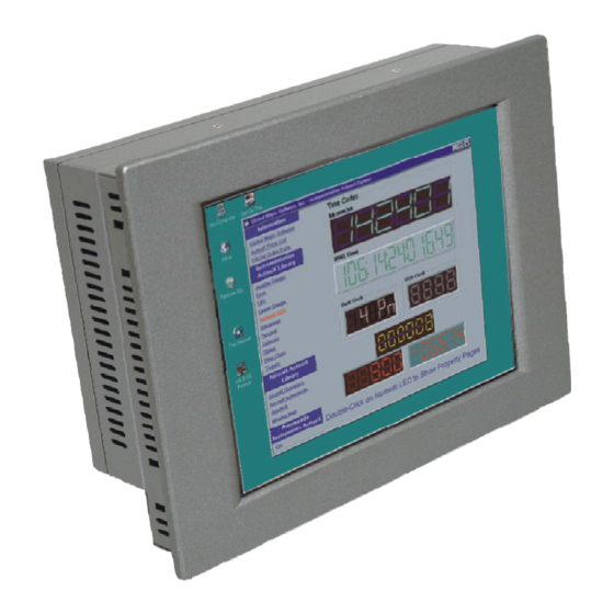
LAN, USB 2.0, audio, VGA port, serial port, keyboard/mouse connectors and power switch. 1.2.2 Front Panel The front side of the PPC-2706/PPC-2708 is a flat panel TFT LCD screen surrounded by an aluminum frame. Figure 1-1: PPC-2706/PPC-2708 Front View... -
Page 14: Rear Panel
Figure 1-3: PPC-2708 Rear View 1.2.4 Top Panel The top panel of PPC-2706 provides access to two retention screw holes that support to secure the back cover to the chassis. The retention screw holes are circled in Figure 1-4 below. -
Page 15: Bottom Panel
Figure 1-4: PPC-2706 Top View Figure 1-5: PPC-2708 Top View 1.2.5 Bottom Panel The bottom panel of the PPC-2706/PPC-2708 has the following I/O interfaces (Figure 1-6 and Figure 1-7): 1 x Serial port (COM) connector 1 x PS/2 keyboard/mouse connector... -
Page 16: Internal Overview
Figure 1-7: PPC-2708 Bottom View 1.3 Internal Overview The PPC-2706/2708 internal components are configured in a two level format. The motherboard and 2.5” HDD are installed on a metal sheet that protects the rear of the TFT LCD screen. Below the metal sheet is a circuit board that is connected to the screen and the motherboard. -
Page 17: System Specifications
1 x TFT LCD screen The technical specifications for these components and the system are shown in the sections below. 1.4.2 System Specifications The technical specifications for the PPC-2706 and PPC-2708 systems are listed in Table 1-2. SPECIFICATION PPC-2706 PPC-2708... -
Page 18: Motherboard Specifications
Net/Gross Weight IP65 compliant Front Panel Protection Table 1-2: PPC-2706/PPC-2708 Specifications 1.4.3 Motherboard Specifications The PPC-2706 and PPC-2708 both come with a WAFER-LX motherboard. The technical specifications of the motherboard are listed in Table 1-3. Specification WAFER-LX 3.5” form factor Form Factor AMD®... -
Page 19: Flat Panel Screen
1.4.4 Flat Panel Screen 1.4.4.1 PPC-2706 Flat Panel Screen Specifications The PPC-2706 comes with a 6.5” TFT LCD monitor at the front of the flat panel PC (see Figure 1-1). The specifications for the LCD monitor are shown in Table 1-4 below. -
Page 20: Table 1-4: 6.5" Tft Lcd Monitor Specifications
PPC-2706/PPC-2708 Panel PC SPECIFICATION PPC-2706 Model AUO G65VN01 V2 Size 6.5” Resolution 640 x 480 (VGA) Active Area (mm) 132.48 x 99.36 Pixel Pitch (mm) 0.207 Mode View Angel (H/V) 140/120 Brightness (cd/m Contrast Ratio 600:1 Response Time Rising=15ms, Falling=10ms Power Consumption (W) 3.86... -
Page 21: Ppc-2708 Flat Panel Screen Specifications
PPC-2706/PPC-2708 Panel PC 1.4.4.2 PPC-2708 Flat Panel Screen Specifications The PPC-2708 comes with an 8.4” TFT LCD monitor at the front of the flat panel PC (see Figure 1-1). The specifications for the LCD monitor are shown in Table 1-5 below. -
Page 22: Dimensions
PPC-2706/PPC-2708 Panel PC 1.5 Dimensions 1.5.1 PPC-2706 Dimensions The dimensions of the PPC-2706 flat panel PC are shown in Figure 1-8 below. Figure 1-8: PPC-2706 Dimensions (units in mm) Page 12... -
Page 23: Ppc-2708 Dimensions
PPC-2706/PPC-2708 Panel PC 1.5.2 PPC-2708 Dimensions The dimensions of the PPC-2708 flat panel PC are shown in Figure 1-9 below. Figure 1-9: PPC-2708 Dimensions (units in mm) Page 13... -
Page 24: Wafer-Lx Motherboard
PPC-2706/PPC-2708 Panel PC Chapter WAFER-LX Motherboard Page 14... -
Page 25: Introduction
PPC-2706/PPC-2708 Panel PC 2.1 Introduction The PPC-2706 and PPC-2708 flat screen PC both contain the WAFER-LX motherboard. The motherboard is the heart of any computer and is responsible for transmitting, receiving and processing data as well as driving the different onboard devices. This chapter gives a brief introduction to the WAFER-LX motherboard. -
Page 26: Amd Geode™ Lx 800 500Mhz Power Management
PPC-2706/PPC-2708 Panel PC ® 2.2.2 AMD Geode™ LX 800 500MHz Power Management ® The power management for the 500MHz AMD Geode™ LX 800 is listed below: 1.8W Typical (3.9W TDP) @ 500MHz GeodeLink active hardware power management Hardware support for standard ACPI software power management... -
Page 27: Ethernet Controller Specifications
PPC-2706/PPC-2708 Panel PC AC97 specification v2.3 compliant interface to multiple audio codecs: Serial In, Serial Out, Sync Out, Bit Clock In Legacy “PC Beep” support Diverse Device 82xx Legacy Devices IR Communication Port System Management Bus (SMB) Controller LPC (Low Pin Count) Port... -
Page 28: Peripheral Device Interfaces, Connectors, And Slots
PPC-2706/PPC-2708 Panel PC Supports ACPI power management Provides PCI bus master data transfer 2.5 Peripheral Device Interfaces, Connectors, and Slots The peripheral device connectors, interfaces and slots on the WAFER-LX motherboard are listed in the sections below. 2.5.1 OEM Options Many of the peripheral device connectors listed below are not connected to any devices. -
Page 29: External Peripheral Device Connectors
PPC-2706/PPC-2708 Panel PC 1 x Parallel port connector 1 x Reset button connector 1 x RS-232/422/485 serial port connector 2 x SATA connectors 1 x Suspend power input connector 1 x TFT LCD LVDS interface connector 1 x TFT LCD TFT interface connector... -
Page 30: Installation And Configuration
PPC-2706/PPC-2708 Panel PC Chapter Installation and Configuration Page 20... -
Page 31: Installation Precautions
PPC-2706/PPC-2708 Panel PC 3.1 Installation Precautions When installing the flat panel PC, please follow the precautions listed below: Power turned off: When installing the flat panel PC, make sure the power is off. Failing to turn off the power may cause severe injury to the body and/or damage to the system. -
Page 32: Unpacking
PPC-2706/PPC-2708 Panel PC Install system fan Step 3: Install HDD Step 4: Install the SO-DIMM memory module Step 5: Mount the flat panel PC Step 6: Connect peripheral devices to the bottom panel of the flat panel PC Step 7:... -
Page 33: Packing List
The back cover is secured to the chassis with six retention screws, two on the top panel, two on the rear panel, one on the right panel and one on the left panel (Figure 3-1). Remove the six retention screws and lift the cover off the PPC-2706. Page 23... -
Page 34: Ppc-2708 Back Cover Removal
PPC-2706/PPC-2708 Panel PC Figure 3-1: PPC-2706 Back Cover Retention Screws 3.5.2 PPC-2708 Back Cover Removal The back cover is secured to the chassis with seven retention screws on the rear panel (Figure 3-2). Remove the seven retention screws and lift the cover off the PPC-2708. -
Page 35: Jumper Settings
PPC-2706/PPC-2708 Panel PC 3.6 Jumper Settings NOTE: A jumper is a metal bridge that is used to close an electrical circuit. It consists of two metal pins and a small metal clip (often protected by a plastic cover) that slides over the pins to connect them. -
Page 36: Jp1: At Power Select Jumper Settings
PPC-2706/PPC-2708 Panel PC Figure 3-3: Jumper Locations 3.6.1 JP1: AT Power Select Jumper Settings The AT/ATX Power Mode Select jumper specifies the systems power mode. AT Power Select Description Short Use AT power Default Open Use ATX power Table 3-1: AT Power Select Jumper Settings 3.6.2 CN7: Clear CMOS Setup... -
Page 37: Jp2: Com3 Setup Jumper Settings
Table 3-3: COM3 Setup Jumper Settings 3.7 System Fan Installation 3.7.1 PPC-2706 System Fan Installation The fan bracket of the PPC-2706 is secured to the chassis with three retention Step 1: screws inside the chassis (Figure 3-4). Remove the three retention screws. Lift the fan bracket off the PPC-2706 flat panel PC. -
Page 38: Figure 3-4: Ppc-2706 Fan Bracket Removal
PPC-2706/PPC-2708 Panel PC Figure 3-4: PPC-2706 Fan Bracket Removal Install the system fan module to the fan bracket with four retention screws Step 2: (Figure 3-11). Figure 3-5: PPC-2706 System Fan Installation Use a cable tie to tie the system fan module cables as shown in Figure 3-6. -
Page 39: Figure 3-6: Ppc-2706 Fan Module Cables
PPC-2706/PPC-2708 Panel PC Figure 3-6: PPC-2706 Fan Module Cables Locate the fan connector (CN4) on the motherboard (Figure 3-7). Insert the fan Step 4: connector of the fan module to the fan connector on the motherboard. Figure 3-7: PPC-2706 Fan Connector Location... -
Page 40: Ppc-2708 System Fan Installation
PPC-2706/PPC-2708 Panel PC 3.7.2 PPC-2708 System Fan Installation Install the system fan module to the fan bracket with four retention screws Step 1: (Figure 3-11). Figure 3-8: PPC-2708 System Fan Installation Attach the cable clip on the fan bracket as shown in Figure 3-6. Secure the fan Step 2: cable with the cable clip. -
Page 41: Hdd Installation
Install the fan bracket into the system with two retention screws. Step 4: Figure 3-11: PPC-2708 Fan Bracket Installation 3.8 HDD Installation 3.8.1 PPC-2706 HDD Installation To install the HDD into the PPC-2706, please follow the steps below: Page 31... -
Page 42: Ppc-2708 Hdd Installation
Step 4: to the rear of HDD. Reconnect the fan cable to the motherboard. Install the HDD into the PPC-2706 by aligning the retention screw holes in the Step 5: HDD brackets with the retention screw holes on the chassis. Insert the three retention screws. -
Page 43: Figure 3-13: Hdd Bracket Retention Screws
PPC-2706/PPC-2708 Panel PC The HDD bracket is attached to the platform by four retention screws. Remove Step 2: the four retention screws from the platform (Figure 3-13). Figure 3-13: HDD Bracket Retention Screws Attach the HDD brackets to the HDD. To do this, align the four retention screw... -
Page 44: Compactflash® Card Installation
3.9 CompactFlash® Card Installation 3.9.1 PPC-2706 CF Card Installation The PPC-2706 embedded motherboard has one CF Type II slot on the solder side. To install the CF card, follow the instructions below. Remove the back cover. See Section 3.5 above. -
Page 45: Figure 3-16: Ppc-2706 Motherboard Retention Screws
Lift the chassis up and locate the CF slot. Insert a CF card into the slot (Figure Step 6: 3-18). Figure 3-18: PPC-2706 CF Card Location Secure the motherboard with the copper pillar first. Then, Insert all previously Step 7: removed retention screws into the PPC-2706 to secure the motherboard and the Page 35... -
Page 46: Ppc-2708 Cf Card Installation
PPC-2706/PPC-2708 Panel PC chassis. Remember to connect the grounding cable when inserting the retention screw to the copper pillar (Figure 3-19). Figure 3-19: PPC-2706 Grounding Cable Install the previously removed HDD bracket and reconnect the fan cable. Step 8: Replace the top cover. Once replaced reinsert the six previously removed Step 9: retention screws. -
Page 47: Memory Module Installation
PPC-2706/PPC-2708 Panel PC Figure 3-21: PPC-2708 Chassis Retention Screws (Inside) Lift the chassis up and locate the CF slot. Insert a CF card into the slot (Figure Step 5: 3-18). Figure 3-22: PPC-2708 CF Card Location Insert all previously removed retention screws into the PPC-2708 to secure the Step 6: chassis. -
Page 48: Sata - Al Iraid Driver Installation
The ALi driver is especially required if SATA drives are the only hard disk drives in the PPC-2706/PPC-2708 system. Otherwise, the Windows installation program may fail to locate the hard drives whether configuring the SATA disk drives into RAID volumes or using them as individual disk drives. -
Page 49: Installation Steps During Windows Xp Installation
PPC-2706/PPC-2708 Panel PC The system BIOS can identify SATA disk drives, but cannot control their operation. The separately installed driver therefore is necessary. 3.11.1 Installation Steps During Windows XP Installation Enable SATA ROM using the BIOS configuration utility. The process has been Step 1: detailed in Appendix E. -
Page 50: Installation Steps Under Existing Windows Xp
PPC-2706/PPC-2708 Panel PC The follow-up window lists out the devices to be installed, in which selected ALi Step 9: controller(s) should be included. Repeat step 5, but select ALi ATA/RAID Controller at step 7. If both controllers Step 10: are installed, go to next step. -
Page 51: Mounting The System
PC does not fall down and get damaged. The five methods of mounting the PPC-2706/PPC-2708 are listed below. Wall mounting... -
Page 52: Figure 3-24: Wall-Mounting Bracket
PPC-2706/PPC-2708 Panel PC Secure the mounting-bracket to the wall by inserting the retention screws into Step 5: the four pilot holes and tightening them (Figure 3-24). Figure 3-24: Wall-mounting Bracket Insert the four monitor mounting screws provided in the wall mounting kit into the... -
Page 53: Panel Mounting
Select the position on the panel to mount the PPC-2706. Step 1: Cut out a section from the panel that corresponds to the rear panel dimensions Step 2: of the PPC-2706. Take care that the panel section that is cut out is smaller than Page 43... -
Page 54: Figure 3-27: Ppc-2706 Panel Opening
PPC-2706/PPC-2708 Panel PC the overall size of the metal frame that surrounds the PPC-2706 but just large enough for the rear panel of the PPC-2706 to fit through (Figure 3-27). Figure 3-27: PPC-2706 Panel Opening Slide the PPC-2706 through the hole until the aluminum frame is flush against Step 3: the panel. -
Page 55: Ppc-2708 Panel Mounting
PPC-2706/PPC-2708 Panel PC Figure 3-28: PPC-2706 Panel Mounting 3.12.2.2 PPC-2708 Panel Mounting To mount the PPC-2708 flat panel PC into a panel, please follow the steps below. Select the position on the panel to mount the PPC-2708. Step 1: Cut out a section from the panel that corresponds to the rear panel dimensions Step 2: of the PPC-2708. -
Page 56: Arm Mounting
Figure 3-30: Tighten the Panel Mounting Clamp Screws 3.12.3 Arm Mounting The PPC-2706/PPC-2708 is VESA (Video Electronics Standards Association) compliant and can be mounted on an arm with a 100mm interface pad. To mount the PPC-2706//PPC-2708 on an arm, please follow the steps below. -
Page 57: Figure 3-31: Arm Mounting Retention Screw Holes
100mm interface pad. If the mounting arm is not VESA compliant it cannot be used to support the PPC-2706/PPC-2708 flat panel Once the mounting arm has been firmly attached to the surface, lift the flat panel Step 2: PC onto the interface pad of the mounting arm. -
Page 58: Cabinet And Rack Installation
PPC-2706/PPC-2708 Panel PC 3.12.4 Cabinet and Rack Installation The PPC-2706/PPC-2708 flat panel PC can be installed into a cabinet or rack. The installation procedures are similar to the panel mounting installation. To do this, please follow the steps below: NOTE:... -
Page 59: Figure 3-33: Ppc-2706 Rack And Cabinet Mounting
PPC-2706/PPC-2708 Panel PC Figure 3-33: PPC-2706 Rack and Cabinet Mounting Slide the PPC-2708 flat panel PC with the attached rack/cabinet bracket into a Step 4: rack or cabinet (Figure 3-34). Figure 3-34: Install into a Rack/Cabinet Once the PPC-2708 flat panel PC with the attached rack/cabinet bracket has... -
Page 60: Ppc-2708 Cabinet And Rack Installation
PPC-2706/PPC-2708 Panel PC 3.12.4.2 PPC-2708 Cabinet and Rack Installation Slide the rear chassis of the PPC-2708 flat panel PC through the rack/cabinet Step 1: bracket until the aluminum frame is flush against the front of the bracket (Figure 3-35). Figure 3-35: The Rack/Cabinet Bracket... -
Page 61: Din Mounting
0: 3.12.5 DIN Mounting To mount the PPC-2706/PPC-2708 flat panel PC onto a DIN rail, please follow the steps below. Attach the DIN rail mounting bracket to the rear of the panel PC. Secure the Step 1: bracket to the panel PC with the supplied retention screws (Figure 3-37). -
Page 62: Figure 3-37: Din Rail Mounting Bracket
PPC-2706/PPC-2708 Panel PC Figure 3-37: DIN Rail Mounting Bracket Make sure the inserted screw in the center of the bracket is at the lowest Step 2: position of the elongated hole (Figure 3-38). Figure 3-38: Screw Locations Place the DIN rail flush against the back of the mounting bracket making sure Step 3: the edges of the rail are between the upper and lower clamps (Figure 3-39). -
Page 63: Rear Panel Connectors
Figure 3-40: Secure the Assembly to the DIN Rail 3.13 Rear Panel Connectors 3.13.1 LCD Panel Connection To connect the PPC-2706/PPC-2708 flat panel PC to a second monitor, a conventional CRT VGA monitor connector is located on the bottom panel. This panel is a 15-pin, female D-SUB connector. -
Page 64: Ethernet Connection
PS/2 connector on the external peripheral interface panel. 3.14 System Maintenance If the components of the PPC-2706/PPC-2708 fail they must be replaced. Please contact the system reseller or vendor to purchase the replacement parts. Replacement instructions for the above listed components are described below. -
Page 65: Gasket Replacement
PPC-2706/PPC-2708 Panel PC Chapter Gasket Replacement Page 55... -
Page 66: Figure 4-1: Gasket Replacement
PPC-2706/PPC-2708 Panel PC 4.1 Gasket Replacement A gasket used for a long time may gradually lose its ability to protect the monitor from fluids and vapors; scratches or dirt may also accumulate. It is recommended that the gasket be replaced yearly. -
Page 67: Ami Bios Setup
PPC-2706/PPC-2708 Panel PC Chapter AMI BIOS Setup Page 57... -
Page 68: Introduction
PPC-2706/PPC-2708 Panel PC 5.1 Introduction A licensed copy of Phoenix Award BIOS is preprogrammed into the ROM BIOS. The BIOS setup program allows users to modify the basic system configuration. This chapter describes how to access the BIOS setup program and the configuration options that may be changed. -
Page 69: Getting Help
PPC-2706/PPC-2708 Panel PC Previous values for the page menu items Fail-safe defaults for the current page menu items Optimized defaults for the current page menu items Menu in BIOS Save changes and Exit BIOS Table 5-1: BIOS Navigation Keys 5.1.3 Getting Help When F1 is pressed a small help window describing the appropriate keys to use and the possible selections for the highlighted item appears. - Page 70 PPC-2706/PPC-2708 Panel PC BIOS Menu 1: Award BIOS CMOS Setup Utility NOTE: The following sections will completely describe the menus listed below and the configuration options available to users. The following menu options are seen in BIOS Menu 1. Standard CMOS Features: Changes the basic system configuration.
-
Page 71: Load Fail-Safe Defaults
PPC-2706/PPC-2708 Panel PC Load Fail-Safe Defaults Use the Load Fail-Safe Defaults option to load failsafe default values for each BIOS parameter in the setup menus. Press F6 for this operation on any page. Load Optimized Defaults Use the Load Optimized Defaults option to load optimal default values for each BIOS parameter in the setup menus. -
Page 72: Standard Cmos Features
PPC-2706/PPC-2708 Panel PC 5.2 Standard CMOS Features Use the Standard CMOS Features BIOS menu (BIOS Menu 2) to set basic BIOS configuration options. BIOS Menu 2: Standard CMOS Features Date [Day mm:dd:yyyy] Use the Date option to set the system date. -
Page 73: Drive A [None]
PPC-2706/PPC-2708 Panel PC IDE Secondary Slave IDE device configurations are changed or set in the IDE Configuration menu. If an IDE device is detected, and one of the above listed two BIOS configuration options is selected, the IDE configuration options shown in Section 5.2.1 appear. -
Page 74: Ide Primary Master/Slave
PPC-2706/PPC-2708 Panel PC Base Memory: The Base Memory is NOT user configurable. The POST determines the amount of base (or conventional) memory installed in the system. The value of the base memory is typically 512K for systems with 512K memory installed, or 640K for systems with 640K or more memory installed. -
Page 75: Access Mode [Auto]
PPC-2706/PPC-2708 Panel PC inaccessible and any drives attached to it are undetected. (Default) Setting this option allows the device to be automatically Auto detected by the BIOS. Selecting this option allows manual configuration of the Manual device on the IDE channel in BIOS. -
Page 76: Advanced Bios Features
PPC-2706/PPC-2708 Panel PC Head The Head specification indicates how many logical heads are on the HDD installed in the system. Precomp The Precomp specification indicates on what track the write precompensation begins. Landing Zone The Landing Zone specification indicates where the disk head will park itself after the system powers off. -
Page 77: Virus Warning [Disabled]
PPC-2706/PPC-2708 Panel PC Virus Warning [Disabled] NOTE: Many disk diagnostic programs can cause the above warning message to appear when the program attempts to access the boot sector table. If you are running such a program, it is recommended that the virus protection function be disabled beforehand. -
Page 78: Boot From Lan Control [Disabled]
PPC-2706/PPC-2708 Panel PC Boot From LAN Control [Disabled] Use the BOOT From LAN Control option to enable the system to be booted from a remote system. (Default) The system cannot be booted from a remote system Disabled through the LAN. -
Page 79: Boot Other Device [Enabled]
PPC-2706/PPC-2708 Panel PC HDD-1 HDD-2 HDD-3 ZIP100 USB-FDD USB-ZIP USB-CDROM USB-HDD Disabled Boot Other Device [Enabled] Use the Boot Other Device option to determine whether the system uses a second or third boot device if the first boot device is not found. -
Page 80: Boot Up Numlock Status [On]
PPC-2706/PPC-2708 Panel PC Boot Up Numlock Status [On] Use the Boot Up Numlock Status option to specify the default state of the numeric keypad. The keys on the keypad are not activated. (Default) Activates the keys on the keypad. Gate A20 Option [Fast] Use the Gate A20 Option option to set if the keyboard controller or the chipset controls the Gate A20 switching. -
Page 81: Typematic Delay (Msec) [250]
PPC-2706/PPC-2708 Panel PC 12 characters per second 15 characters per second 20 characters per second 24 characters per second 30 characters per second Typematic Delay (Msec) [250] The Typematic Rate option can only be configured if the Typematic Rate Setting is enabled. -
Page 82: Advanced Chipset Features
PPC-2706/PPC-2708 Panel PC OS Select For DRAM > 64MB [Non-OS2] Use the OS Select For DRAM > 64MB option to specify the operating system. Specifies the operating system used as OS/2. Enabled (Default) Select this option when not using the OS/2 operating Disabled system. -
Page 83: Cpu Frequency [500Mhz]
PPC-2706/PPC-2708 Panel PC BIOS Menu 4: Advanced Chipset Features CPU Frequency [500MHz] Use the CPU Frequency option to set the CPU frequency. The CPU Frequency options are: Auto 200MHz 333MHz 400MHz 433MHz 500MHz (Default) Memory Frequency [333MHz] Use the Memory Frequency option to set the frequency of the installed DRAM modules. -
Page 84: Cas Latency [Auto]
PPC-2706/PPC-2708 Panel PC CAS Latency [Auto] Use the CAS Latency Time option to set the Column Address Strobe (CAS) delay time. The CAS Latency Time options are: Auto (Default) 1.5 nanoseconds 2.0 nanoseconds 2.5 nanoseconds 3.0 nanoseconds 3.5 nanoseconds Interleave Select [LOI] Use the Interleave Select option to specify how the cache memory is interleaved. -
Page 85: Flat Panel Configuration
PPC-2706/PPC-2708 Panel PC Panel & CRT (Default) Flat Panel Configuration [Press Enter] Use the Flat Panel Configuration option to open the Flat Panel Configuration menu. The Flat Panel Configuration options are shown in Section 5.4.1. OnBoard Audio [Enabled] Use the OnBoard Audio option to enable or disable the onboard codec. -
Page 86: Resolution [800 X 600]
PPC-2706/PPC-2708 Panel PC Resolution [800 x 600] The Resolution option can only be configured if the Flat Panel Type option is not set to Auto. Use the Resolution option to set the resolution of the flat panel screen connected to the system. The Resolution options are:... -
Page 87: Integrated Peripherals
PPC-2706/PPC-2708 Panel PC HSYNC Polarity [High] The HSYNC Polarity option can only be configured if the Flat Panel Type option is not set to Auto. Use the HSYNC Polarity option to set the polarity of the HSYNC signal to the panel. -
Page 88: On-Chip Ide Channel 1 [Enabled]
PPC-2706/PPC-2708 Panel PC BIOS Menu 6: Integrated Peripherals On-Chip IDE Channel 1 [Enabled] Use the On-Chip IDE Channel 1 option to specify if the system uses the integrated primary IDE channel or not. The primary IDE channel is not used. -
Page 89: Ide Udma [Auto]
PPC-2706/PPC-2708 Panel PC PIO mode 2 selected with a maximum transfer rate of 8.3MBps. Mode 2 PIO mode 3 selected with a maximum transfer rate of 11.1MBps. Mode 3 PIO mode 4 selected with a maximum transfer rate of 16.6MBps. -
Page 90: Onboard Fdc Controller [Disabled]
PPC-2706/PPC-2708 Panel PC (Default) Block mode is supported. Enabled Onboard FDC Controller [Disabled] Use the Onboard FDC Controller option to enable or disable the onboard floppy controller. If the system is not connected to a floppy disk or uses an adapter for the FDD, this option can be disabled. -
Page 91: Onboard Serial Port 3 [Disabled]
PPC-2706/PPC-2708 Panel PC Onboard Serial Port 3 [Disabled] Use the Onboard Serial Port 3 option to select the I/O address and IRQ for the onboard serial port 2. The serial port can be disabled or the I/O address and the IRQ can be automatically selected by the BIOS. -
Page 92: Epp Mode Select [Epp1.7]
PPC-2706/PPC-2708 Panel PC port (ECP) mode. mode supports bi-directional communication between the system and the parallel port device and the transmission rates between the two are much faster than the SPP mode. The parallel port is compatible with both ECP and EPP ECP+EPP devices. -
Page 93: It8888 Isa Decode Io
PPC-2706/PPC-2708 Panel PC 5.5.1 IT8888 ISA Decode IO Use the IT8888 ISA Decode IO menu (BIOS Menu 7 to set the IO memory range for the onboard ISA. BIOS Menu 7: IT8888 ISA Decode IO The IT8888 ISA Decode IO menu has the following common options:... -
Page 94: Decode Io Space N [Enabled]
PPC-2706/PPC-2708 Panel PC Decode I/O Space N Decode I/O Speed N Decode I/O Addr. N [15:0] Decode I/O Size N Where N is an integer in the set [1, 2, 3, 4, 5] and represents a set for the PCI-104 devices that are attached to the system. - Page 95 PPC-2706/PPC-2708 Panel PC 1 Byte 2 Bytes 4 Bytes 8 Bytes 16 Bytes 32 Bytes 64 Bytes 128 Bytes Page 85...
-
Page 96: It8888 Isa Decode Memory
PPC-2706/PPC-2708 Panel PC 5.5.2 IT8888 ISA Decode Memory Use the IT8888 ISA Decode Memory (BIOS Menu 8) to set the resources for the onboard ISA bus. BIOS Menu 8: IT8888 ISA Decode Memory The IT8888 ISA Decode IO menu has the following common options:... -
Page 97: Power Management Setup
PPC-2706/PPC-2708 Panel PC memory resources are reallocated to other applications. (Default) The Nth memory set is enabled and dedicated system Enabled memory resources are allocated to the ISA bus. Decode Memory Speed N [Fast Speed] Use the Decode Memory Speed N option to specify the memory speed of the ISA bus. -
Page 98: Acpi Function [Disabled]
PPC-2706/PPC-2708 Panel PC BIOS Menu 9: Power Management Setup ACPI Function [Disabled] Use the ACPI Function to enable the ACPI (Advanced Configuration and Power Interface) function. ACPI function disabled. Disabled (Default) ACPI function enabled. Enabled Page 88... -
Page 99: Acpi Suspend Type [S1(Pos)]
PPC-2706/PPC-2708 Panel PC ACPI Suspend Type [S1(POS)] Use the ACPI Suspend Type BIOS option to specify the sleep state the system enters when not being used. (Default) System appears off. The CPU is stopped; RAM is S1 (POS) refreshed; the system is running in a low power mode. -
Page 100: Suspend Mode [Disabled]
PPC-2706/PPC-2708 Panel PC 10 Sec 15 Sec 30 Sec 45 Sec 1 Min 5 Min 10 Min 15 Min 30 Min 45 Min 60 Min 90 Min 120 Min x Suspend Mode [Disabled] The Suspend Mode option can only be selected if the Power Management option is set to Legacy. -
Page 101: Pnp/Pci Configurations
PPC-2706/PPC-2708 Panel PC Soft-Off by PWR-BTTN [Instant-Off] Use the Soft-Off by PWR-BTTN option to enabled the system to enter a very low-power-usage state when the power button is pressed. (Default) When the power button is pressed, the system is Instant-Off immediately shutdown. -
Page 102: Reset Configuration Data [Disabled]
PPC-2706/PPC-2708 Panel PC (Default) If the operating system does not meet the Plug and Play specifications, BIOS configures all the devices in the system. Set this option if the system is running Plug and Play aware operating systems. The operating system changes the interrupt, I/O, and DMA settings. -
Page 103: Irq Resources [Press Enter]
PPC-2706/PPC-2708 Panel PC x IRQ Resources [Press Enter] The IRQ Resources option (BIOS Menu 11) can only be selected if the Resources Controlled By option is set to Manual. BIOS Menu 11: IRQ Resources The IRQ Resources menu has the following options:... -
Page 104: Memory Resources [Press Enter]
PPC-2706/PPC-2708 Panel PC The IRQ is reserved by BIOS. Reserved x Memory Resources [Press Enter] The Memory Resources menu (BIOS Menu 12) can only be accessed if the Resources Controlled By option is set to Manual. Use Memory Resources to select a base address and the length for the memory area used by a peripheral that requires high memory. -
Page 105: Pc Health Status
PPC-2706/PPC-2708 Panel PC D400 D800 DC00 x Reserved Memory Length [8K] The Reserved Memory Length option can only be accessed if the Reserved Memory Base option is not set to N/A. The Reserved Memory Length specifies the amount of memory reserved for the peripheral device. The Reserved Memory Length options:... -
Page 106: Shutdown Temperature
PPC-2706/PPC-2708 Panel PC BIOS Menu 13: PC Health Status The following system parameters are monitored by the PC Health Status menu. Shutdown Temperature Use the Shutdown Temperature option to set the temperature when the system should automatically shutdown. CPU Warning Temperature [Disabled] Use the CPU Warning Temperature option to set the CPU temperature that would automatically generate a warning. -
Page 107: System Fan
PPC-2706/PPC-2708 Panel PC System Fan The following system fans are monitored: Current System Fan Voltages The following voltages are monitored: Vcore +3.3 V VccMem +5 V +12 V VBAT(V) Page 97... -
Page 108: A Interface Connectors
PPC-2706/PPC-2708 Panel PC Appendix Interface Connectors Page 98... -
Page 109: Peripheral Interface Connectors
PPC-2706/PPC-2708 Panel PC Peripheral Interface Connectors The PPC-2706/PPC-2708 flat panel PC motherboard, the WAFER-LX, comes with a number of peripheral interface connectors and configuration jumpers listed in Chapter 2. The pinouts for these connectors are listed below: PIN NO. DESCRIPTION... -
Page 110: Tableea-5: Battery Connector (Cn7) Pinouts
PPC-2706/PPC-2708 Panel PC TableeA-5: Battery Connector (CN7) Pinouts PIN NO. DESCRIPTION PIN NO. DESCRIPTION GROUND VCC-IN CHECK1 DATA 3 DATA 11 DATA 4 DATA 12 DATA 5 DATA 13 DATA 6 DATA 14 DATA 7 DATA 15 HDC_CS0# HDC_CS1 GROUND... -
Page 111: Tableea-7: Fan Connector (Cn4) Pinouts
PPC-2706/PPC-2708 Panel PC TableeA-7: Fan Connector (CN4) Pinouts PIN NO. DESCRIPTION PIN NO. DESCRIPTION STEP# INDEX# WDATA# DSA# WGATE# DSKCHG# TRACK0# MOTO0# RDATA# DIR# HEAD# TableeA-8: FDD Connector (CN31) Pinouts PIN NO. DESCRIPTION PIN NO. DESCRIPTION GPO0 GPO1 GPO2 GPO3... -
Page 112: Tableea-10: Secondary Ide Connector (Cn30) Pinouts
PPC-2706/PPC-2708 Panel PC DATA 3 DATA 12 DATA 2 DATA 13 DATA 1 DATA 14 DATA 0 DATA 15 GROUND IDE DRQ GROUND IOW# GROUND IOR# GROUND IDE CHRDY GROUND IDE DACK GROUND–DEFAULT INTERRUPT HDC CS0# HDC CS1# HDD ACTIVE#... -
Page 113: Tableea-12: Keyboard/Mouse Connector (Cn17) Pinouts
PPC-2706/PPC-2708 Panel PC TableeA-12: Keyboard/Mouse Connector (CN17) Pinouts PIN NO. DESCRIPTION Power LED+ Power LED- HDD LED+ HDD LED- TableeA-13: LED Connector (CN5) Pinouts PIN NO. DESCRIPTION PIN NO. DESCRIPTION STB# AFD# ERR# INIT# SLIN# ACK# BUSY SLCT TableeA-14: Parallel Port Connector (CN15) Pinouts PIN NO. -
Page 114: Tableea-16: Rs-232/422/485 Serial Port Connector (Cn16) Pinouts
PPC-2706/PPC-2708 Panel PC CTS# DTR# RI#/Vout TxD485+ TxD485- RxD485+ RxD485- TableeA-16: RS-232/422/485 Serial Port Connector (CN16) Pinouts PIN NO. DESCRIPTION TableeA-17: SATA Drive Connector (CN23 & CN25) Pinouts PIN NO. DESCRIPTION PIN NO. DESCRIPTION CLK+ CLK- LCD_Vcc LCD_Vcc LCD_Vcc LCD_Vcc TableeA-18: TFT LCD LVDS Port Connector (CN29) Pinouts PIN NO. -
Page 115: Tableea-19: Tft Lcd Ttl Port Connector (Cn28) Pinouts
PPC-2706/PPC-2708 Panel PC VSYNC LCD_EN HSYNC DISP_EN TableeA-19: TFT LCD TTL Port Connector (CN28) Pinouts PIN NO. DESCRIPTION PIN NO. DESCRIPTION VCC_USB DATA3- DATA4- DATA3+ DATA4+ VCC_USB Table A-22: USB Port Connector (CN24) Pinouts TS PAGE IS INTENTIONALLY LEFT BLANK... -
Page 116: B Bios Configuration Options
PPC-2706/PPC-2708 Panel PC Appendix BIOS Configuration Options Page 106... -
Page 117: Bios Configuration Options
PPC-2706/PPC-2708 Panel PC BIOS Configuration Options Below is a list of BIOS configuration options described in Chapter 5. Load Fail-Safe Defaults .......................61 Load Optimized Defaults.....................61 Set Supervisor Password....................61 Set User Password ......................61 Save & Exit Setup ........................61 ... - Page 118 PPC-2706/PPC-2708 Panel PC Boot Up Numlock Status [On] ....................70 Gate A20 Option [Fast] ......................70 Typematic Rate Setting [Disabled]..................70 Typematic Rate (Chars/sec) [6] ..................70 Typematic Delay (Msec) [250].....................71 Security Option [Setup].......................71 OS Select For DRAM > 64MB [Non-OS2] ................72 ...
- Page 119 PPC-2706/PPC-2708 Panel PC Onboard Parallel Port [378/IRQ7] ..................81 Parallel Port Mode [SPP] .....................81 EPP Mode Select [EPP1.7] ....................82 ECP Mode Use DMA [1] .......................82 Decode IO Space N [Enabled].....................84 Decode IO Speed N [Fast Speed] ..................84 ...
-
Page 120: C Safety Precautions
PPC-2706/PPC-2708 Panel PC Appendix Safety Precautions Page 110... -
Page 121: Safety Precautions
Do not apply voltage levels that exceed the specified voltage range. Doing so may cause fire and/or an electrical shock. Electric shocks can occur if the PPC-2706/PPC-2708 chassis is opened when the PPC-2706/PPC-2708 is running. Do not drop or insert any objects into the ventilation openings of the PPC-2706/PPC-2708. -
Page 122: Anti-Static Precautions
PPC-2706/PPC-2708 and severe injury to the user. Electrostatic discharge (ESD) can cause serious damage to electronic components, including the PPC-2706/PPC-2708. Dry climates are especially susceptible to ESD. It is therefore critical that whenever the PPC-2706/PPC-2708 is opened and any of the electrical components are handled, the following anti-static precautions are strictly adhered to. -
Page 123: Product Disposal
Please follow the national guidelines for electrical and electronic product disposal. C.2 Maintenance and Cleaning Precautions When maintaining or cleaning the PPC-2706/PPC-2708, please follow the guidelines below. C.2.1 Maintenance and Cleaning Prior to cleaning any part or component of the PPC-2706/PPC-2708, please read the details below. Page 113... -
Page 124: Cleaning Tools
Avoid eating, drinking and smoking within vicinity of the PPC-2706/PPC-2708. C.2.2 Cleaning Tools Some components in the PPC-2706/PPC-2708 may only be cleaned using a product specifically designed for the purpose. In such case, the product will be explicitly mentioned in the cleaning tips. Below is a list of items to use when cleaning the PPC-2706/PPC-2708.
Need help?
Do you have a question about the PPC-2706 and is the answer not in the manual?
Questions and answers